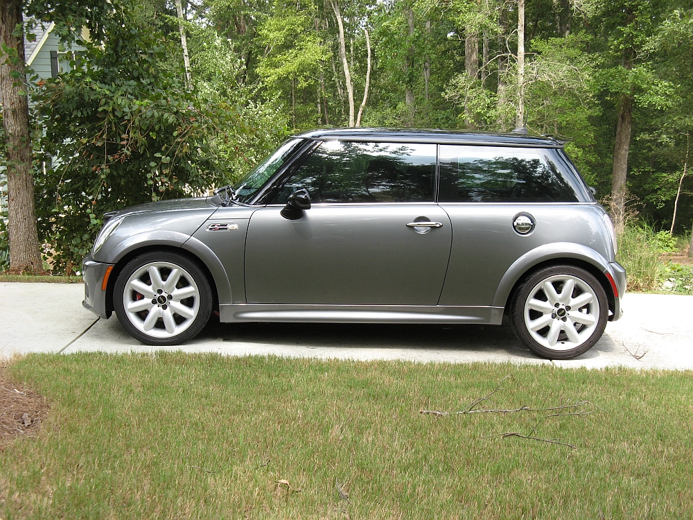


I had been thinking about the '05/'06 supercharged Mini Coopers (aka best years of the R53) for a while, and had even come close to buying one the year before. The R53 designated Mini Cooper S comes with a 1.6 liter, Roots-type Eaton M45 intercooled supercharged Tritec motor (W11) that was co-developed by BMW and Chrysler and manufactured in Brazil- the car otherwise manufactured and assembled entirely in the UK.
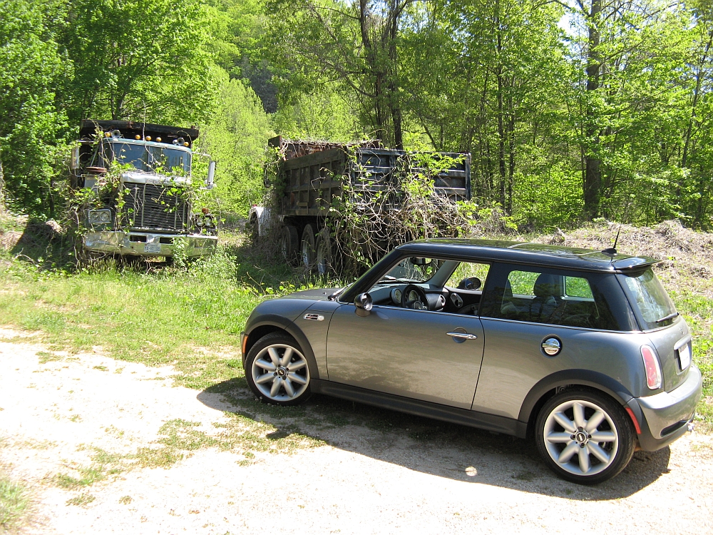
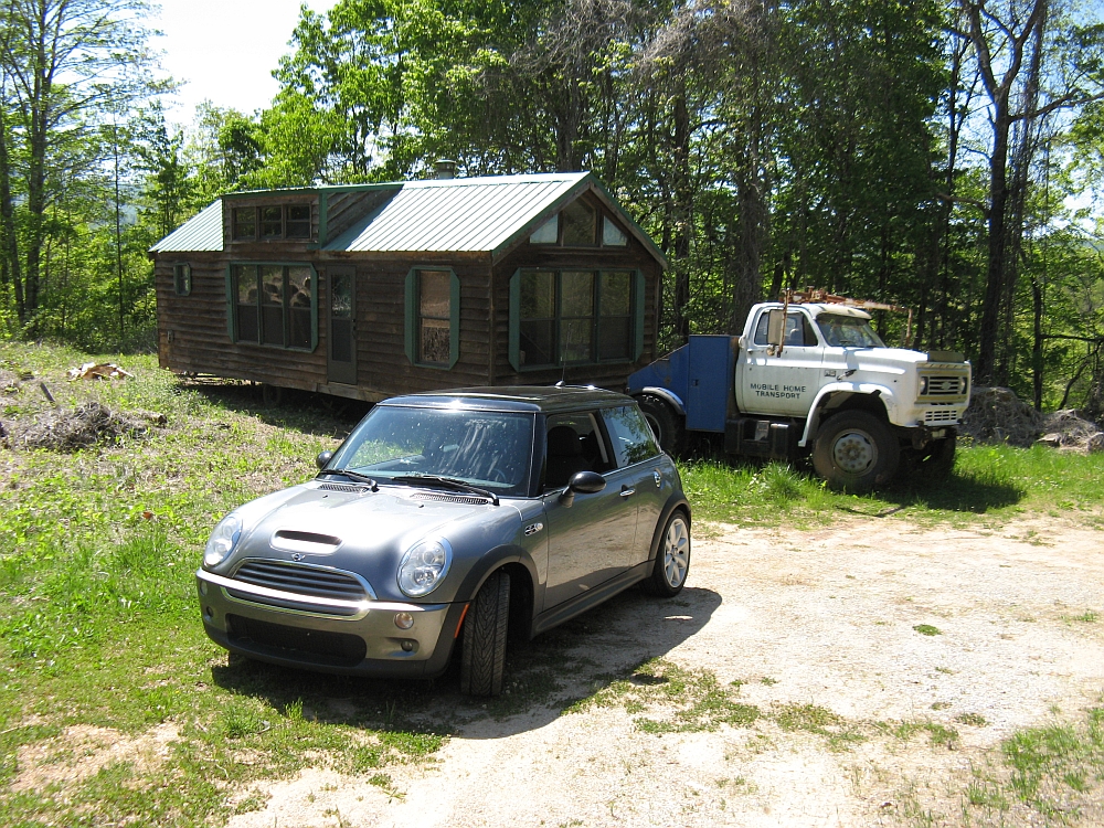
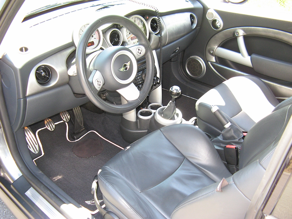
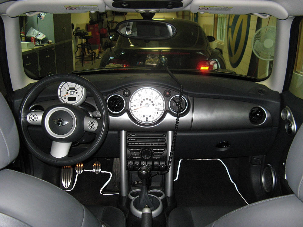
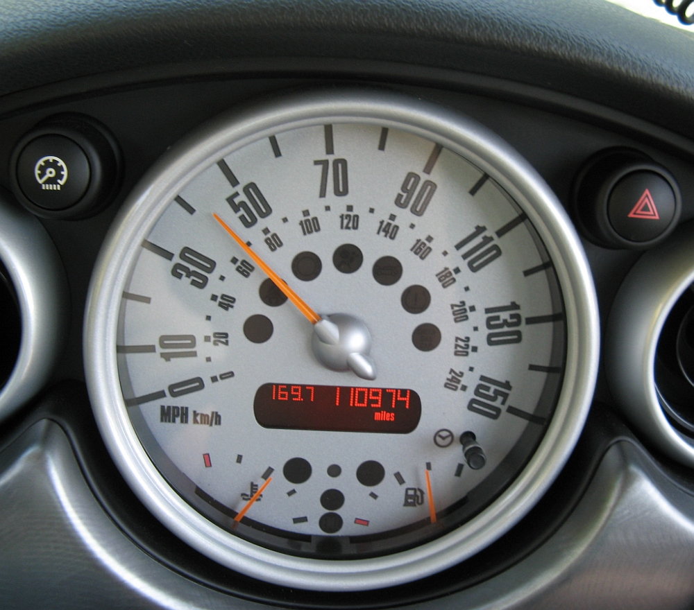
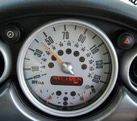
Travel within my 6 hour driving distance circle for business became more prevalent and justified the purchase of this high mileage, but immaculate Mini Cooper S. The interior usually tells the story and this one was like new after 109,000 miles. After a quick test drive and assessment followed by some negotiation the next day over the phone with the dealership that had the car, I closed the deal, picked it up and drove it out of state on Monday of the following week. I started immediately down the mod path but more on that later. More information on the Mini Cooper can be found at the Mini Wikipedia. This Mini came with the Harmon Kardon stereo system which sounds surprisingly good for an OE system (reviewed HERE, adding amplifiers to HK system HERE, and door fixes to make it sound better HERE).
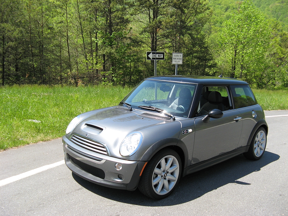
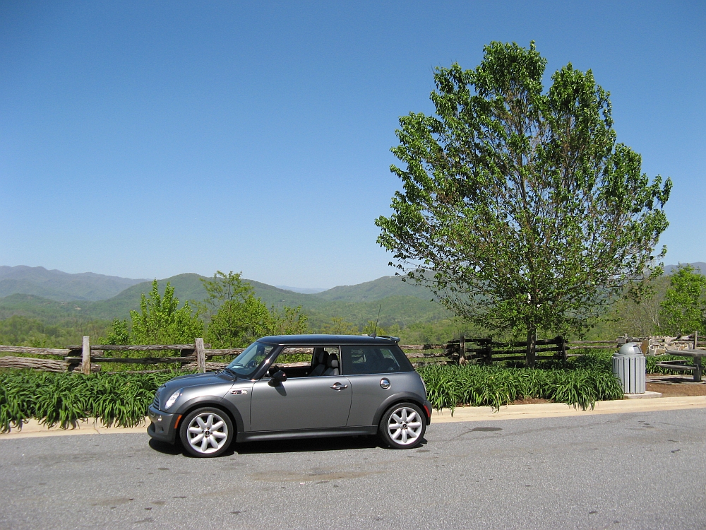
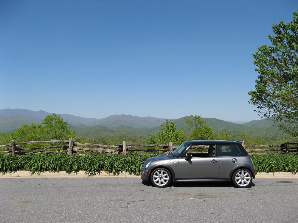
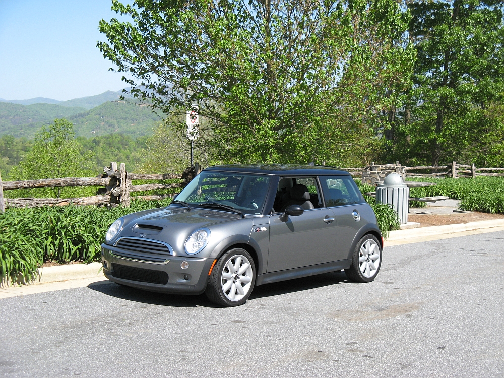
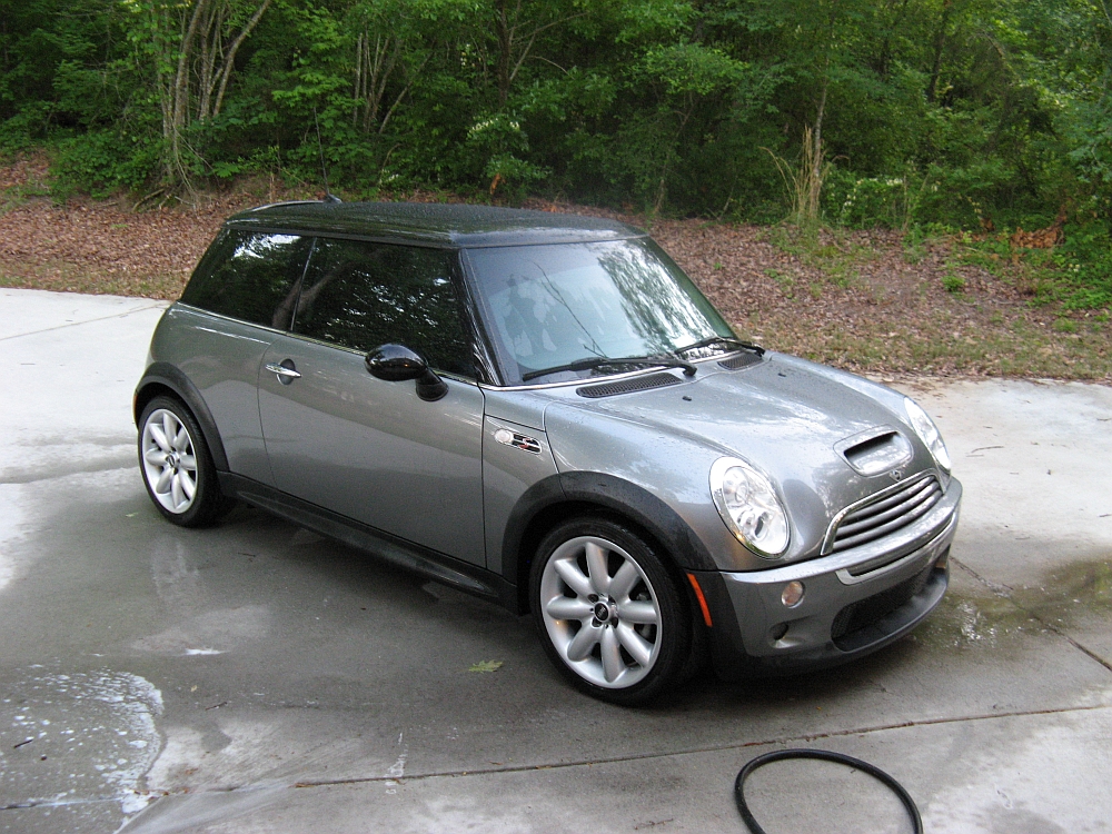
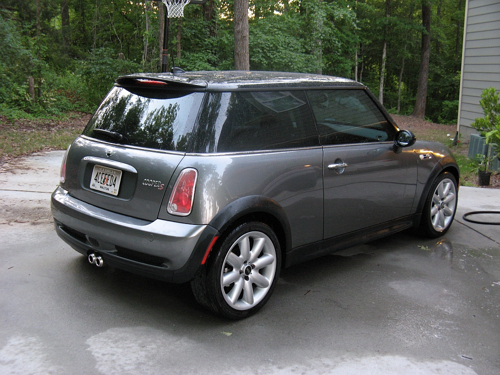
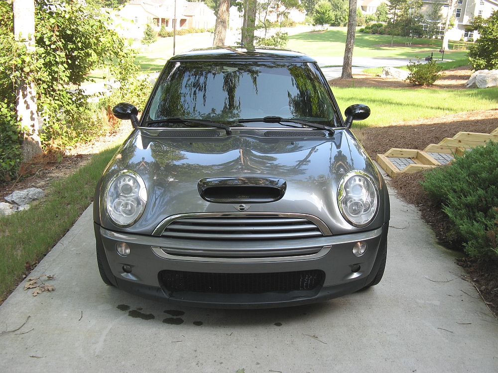
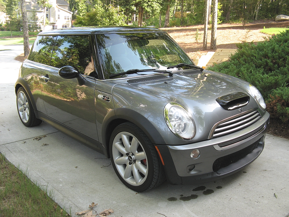
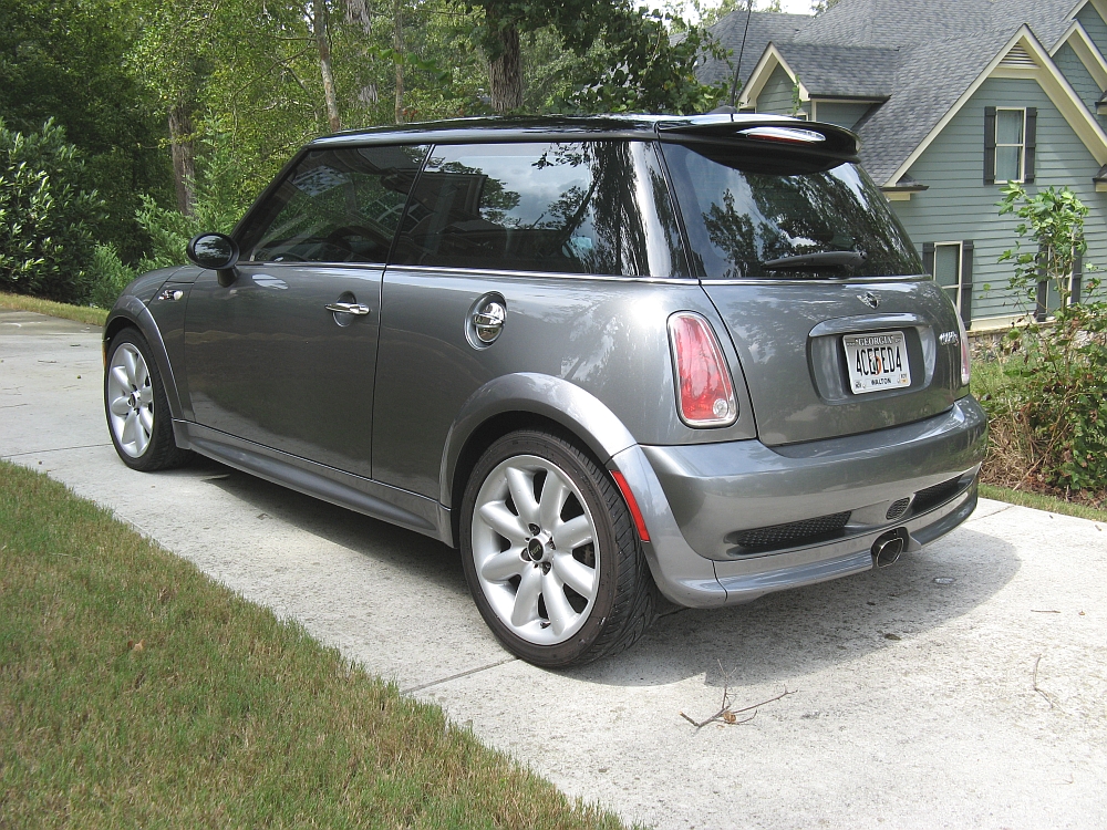
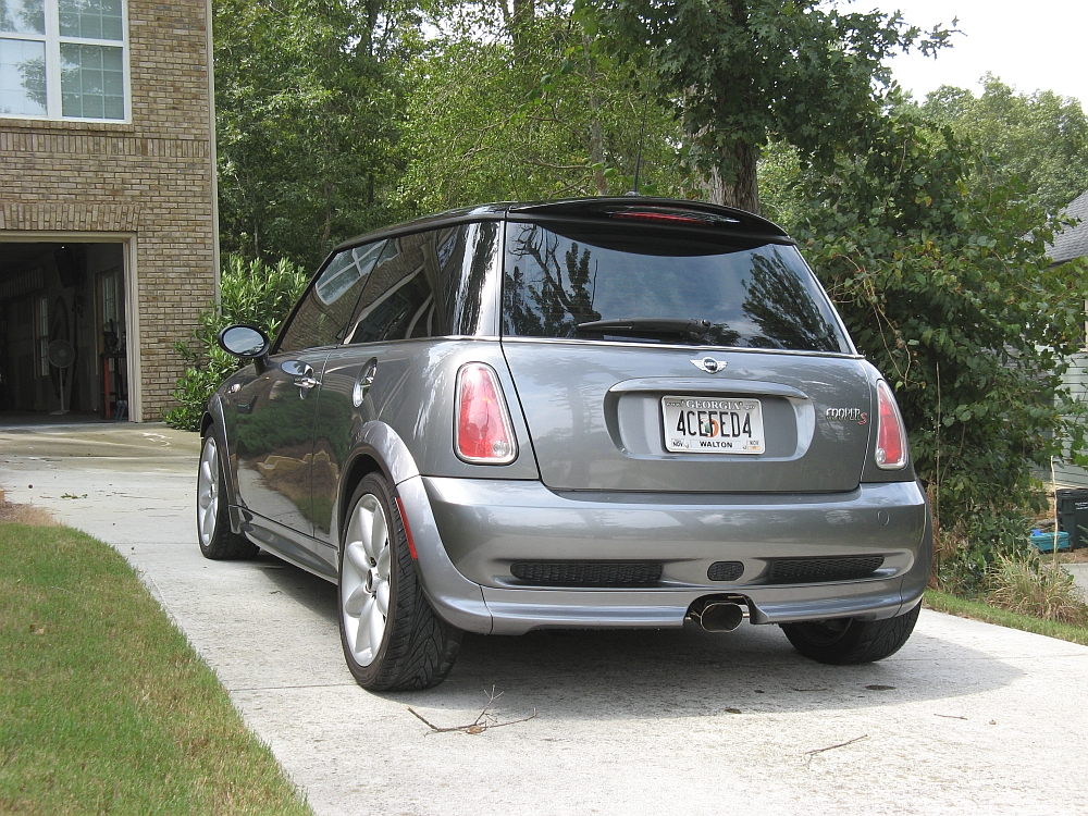
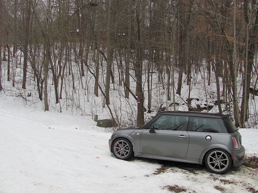
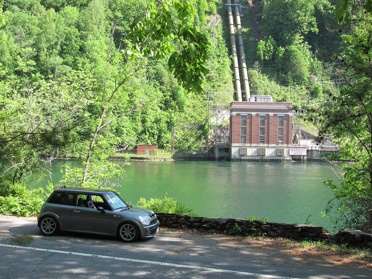
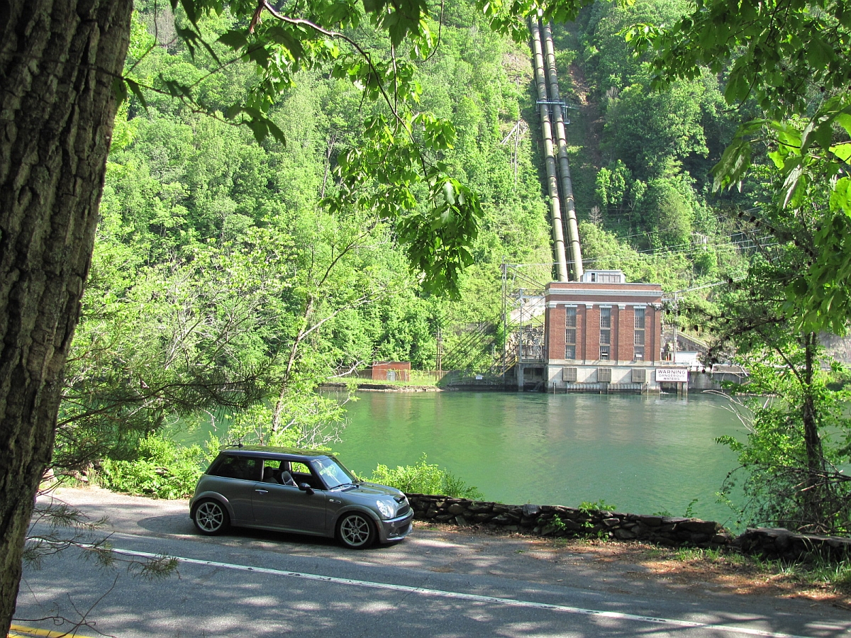
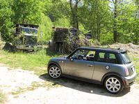
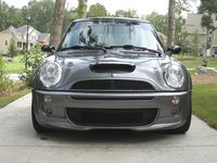
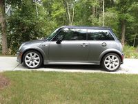
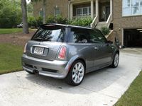
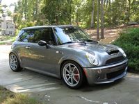
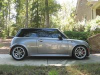
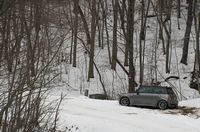
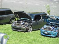
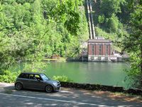
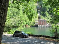
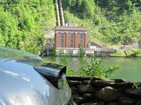
Here are some pics I took the first few weeks I had it, some on HWY 28 (Hellbender) on the way to and from the 2010 Minis on the Dragon GTG:


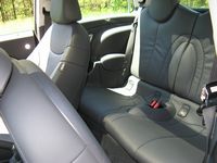

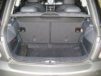
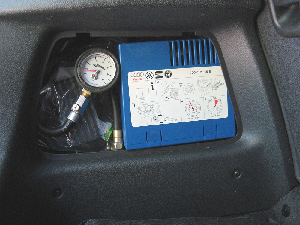
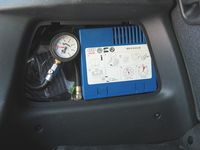
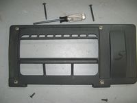
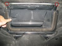
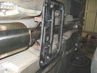
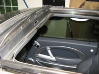
Since the prior (and only other) owner had replaced the run-flat tires with better non run-flat tires, I opted to create my own mobility kit consisting of an old air pump and a tire plug kit stored in the driver side rear hatch compartment. In the other compartment, but not pictured, is a roll of duct tape and some screwdrivers/wrenches- covers fit back on both compartments fine and no rattles.
Jumper cables are stored in a bag under the driver seat:
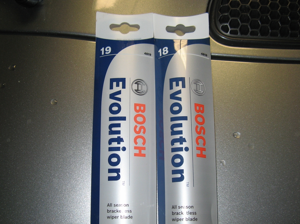
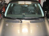
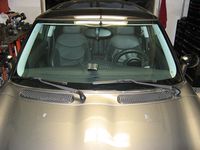
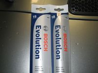
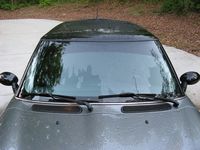
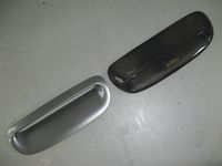
I typically use Rain-X and ONLY use the wipers when it is not raining hard enough for the Rain-X to be effective. The wipers on the Mini are kind of hideous, so that and the fact that the wipers did not work great was an excuse to replace with some Bosch Evolution wiper assemblies- 4818 (18") for the drivers side and 4819 (19") for the passenger side:
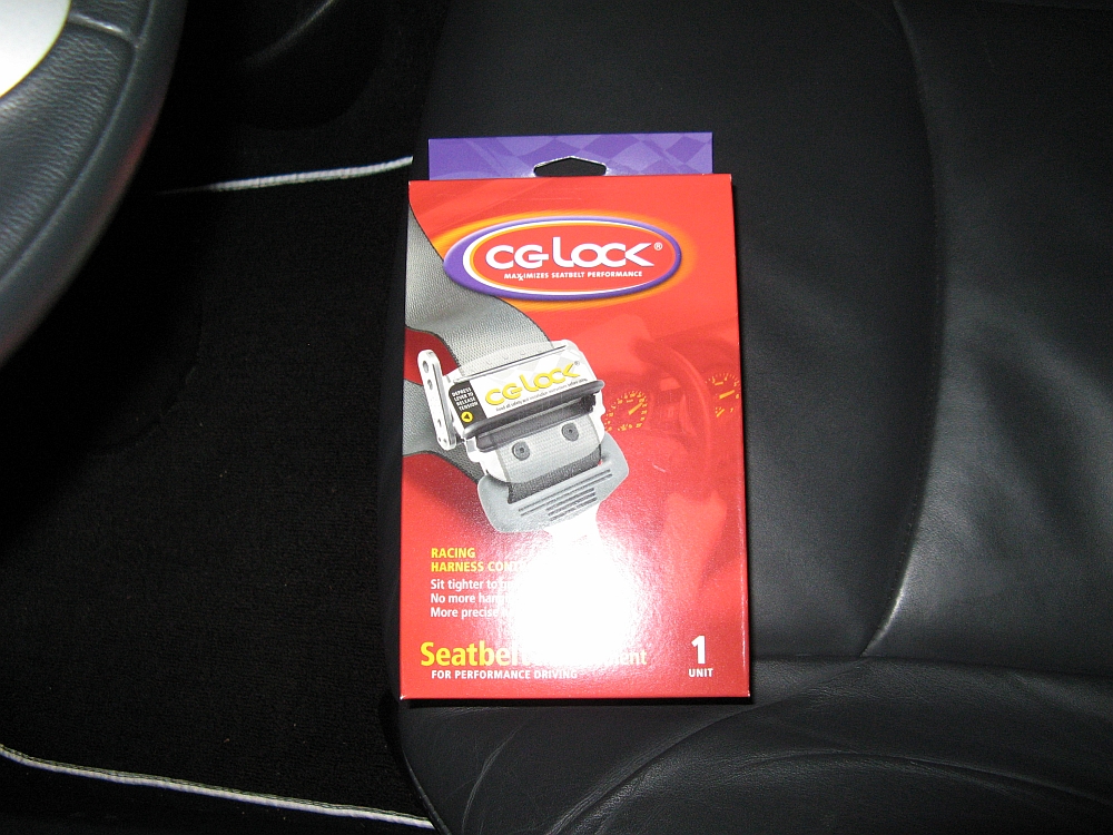
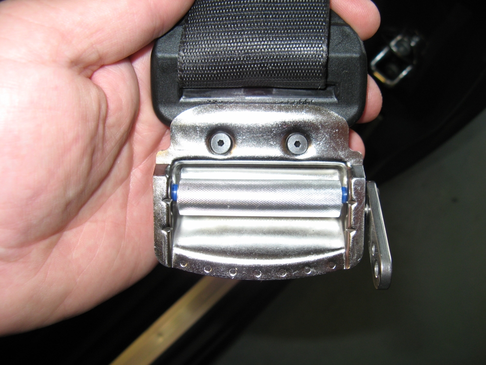
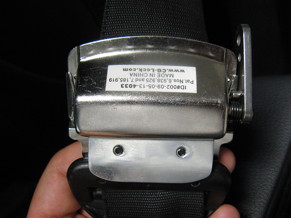
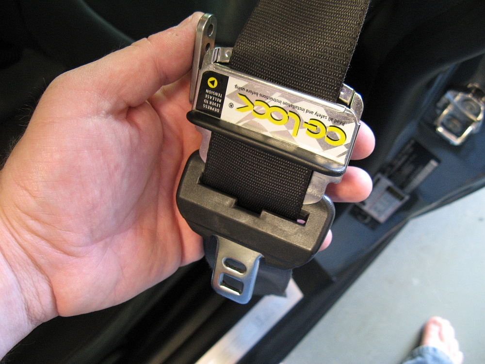
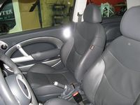
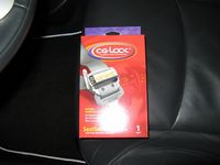
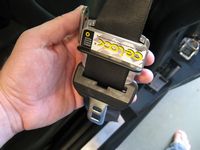
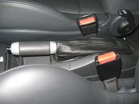
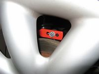
CG-Lock installed, they have been redesigned from the originals I have installed in the BMWs. Provides stability so there is less sliding and repositioning in seat, as seen in the promotional video HERE.
Install instructions HERE, install video HERE.
I had some issues with the first revised CG lock I installed, it felt to me like the knurls on the locking rod were not machined as deep as the first generation ones I had in the BMWs. I sent CG-Lock an email and they promptly replied with a response and sent me another CG-Lock with a return envelope for the defective one- Great customer service with no hassle- THANKS BRUCEThe replacement CG lock works as well as I have come to expect from the use of the first generation models.


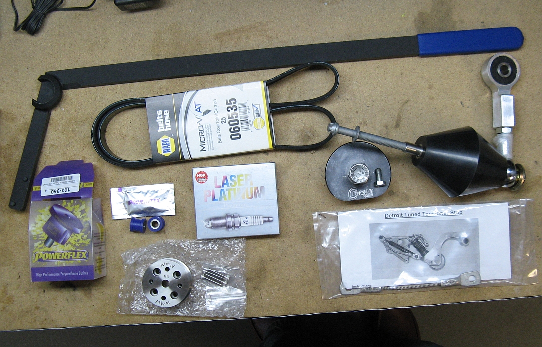
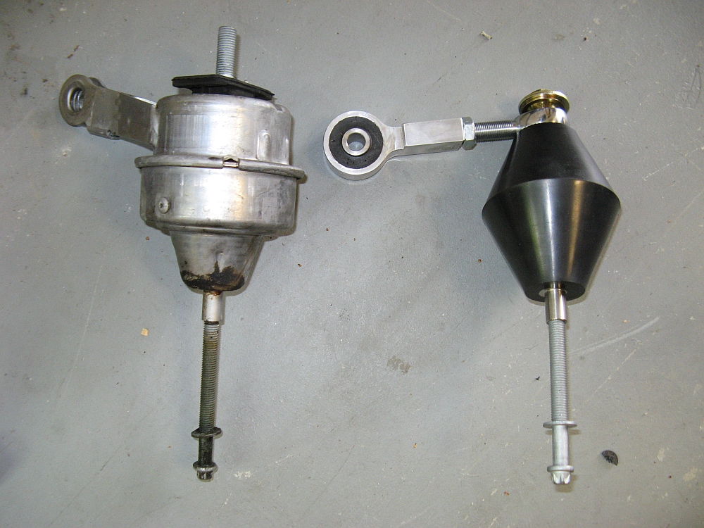
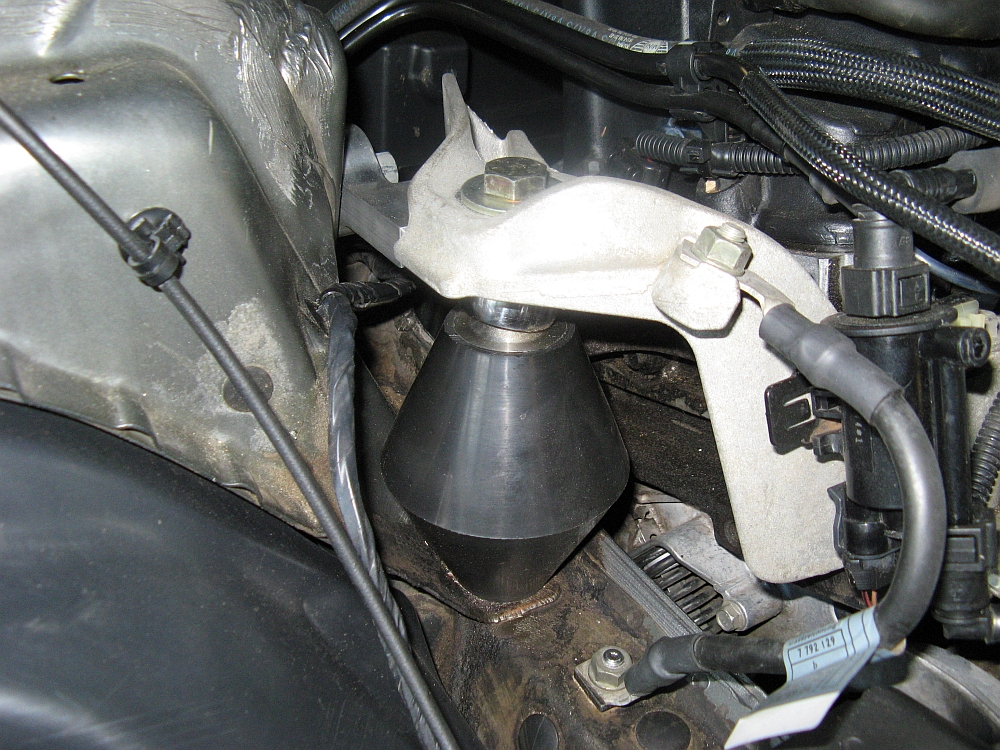
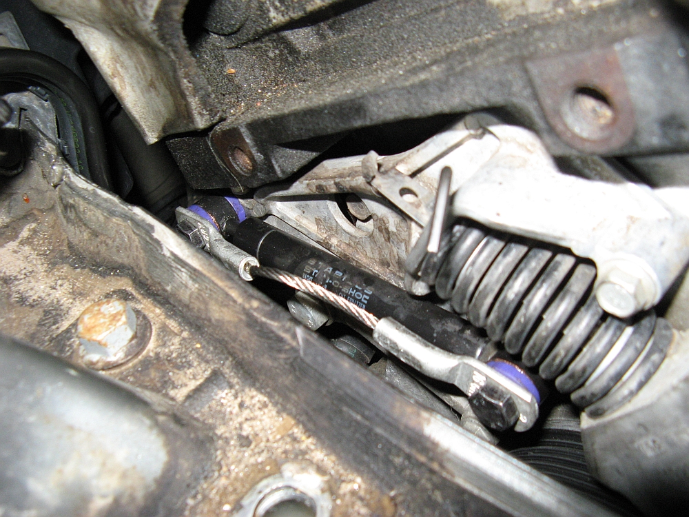
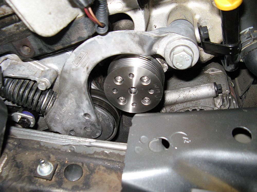
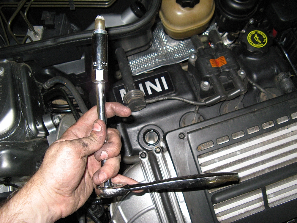
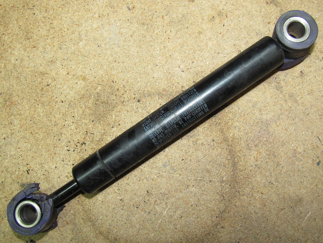
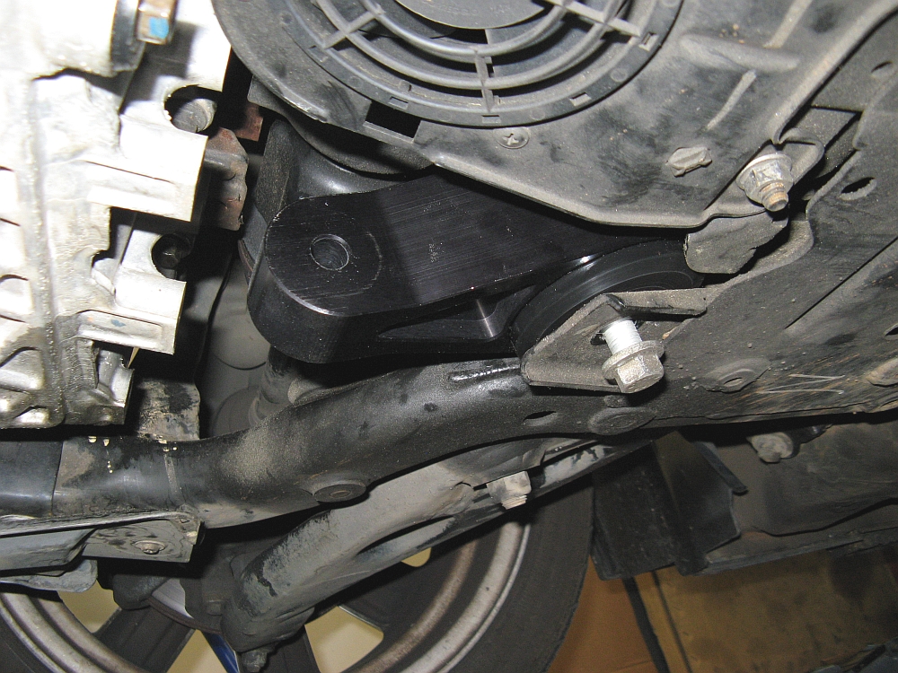
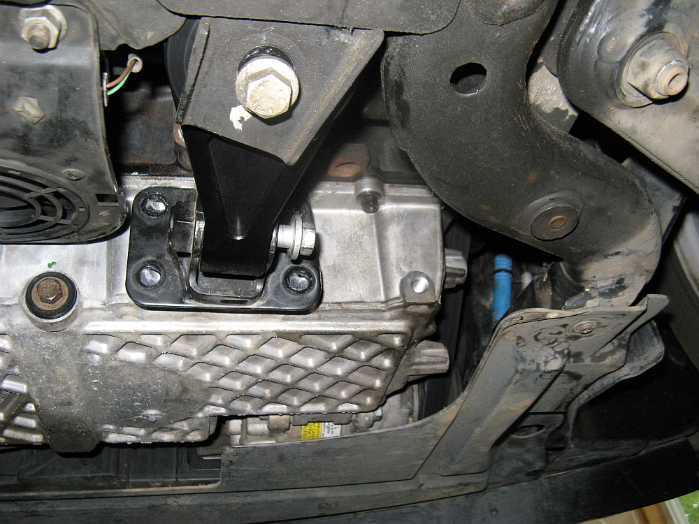
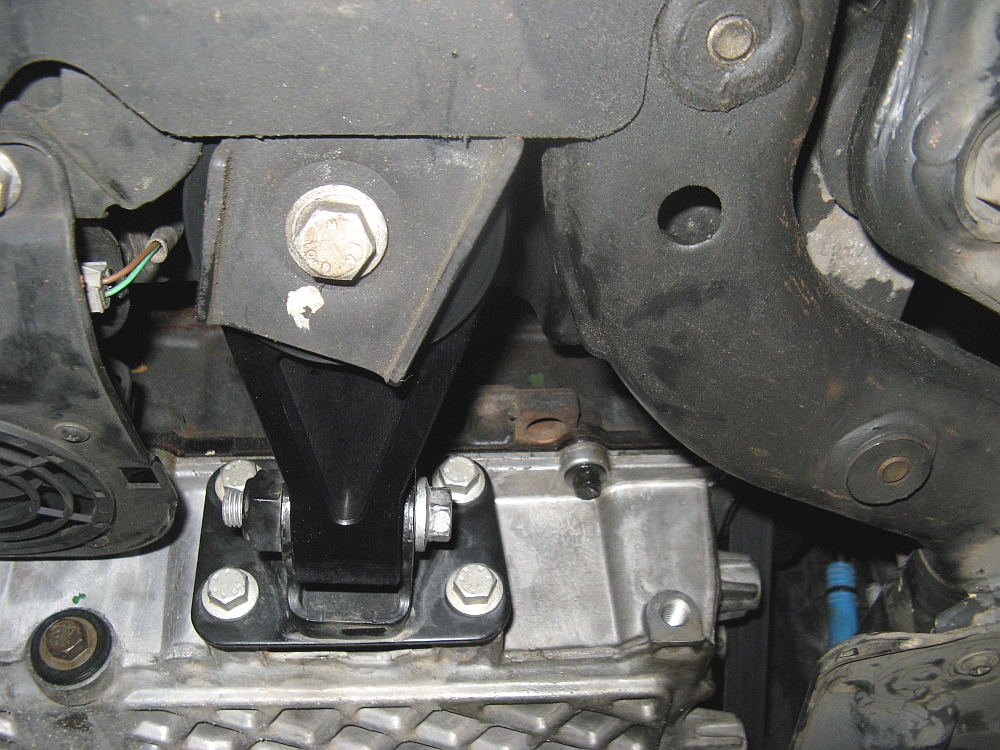
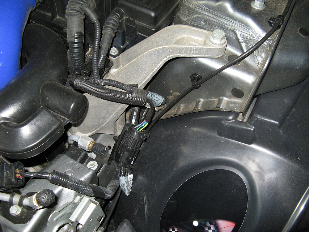
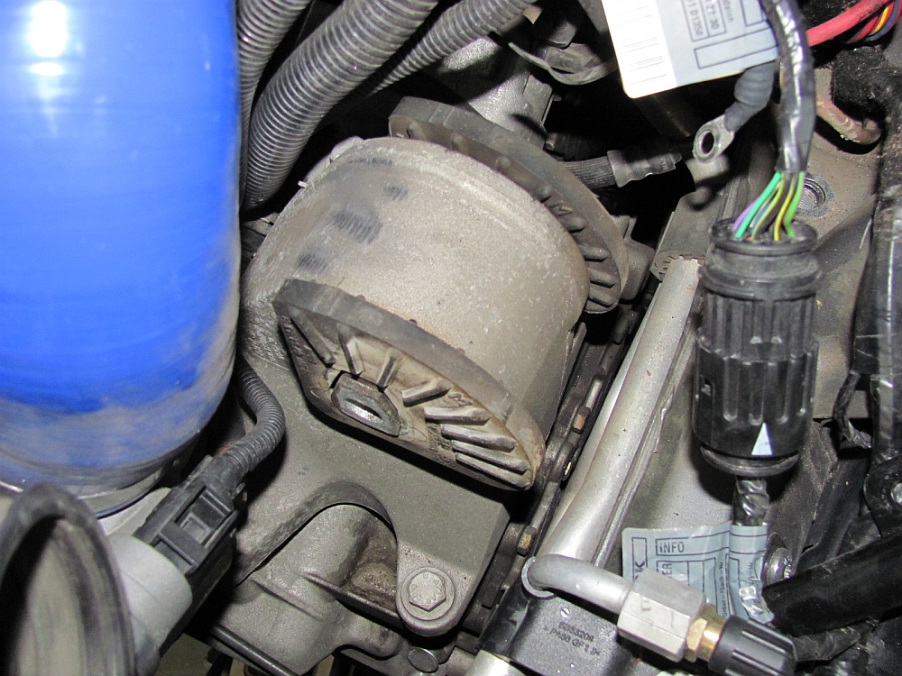
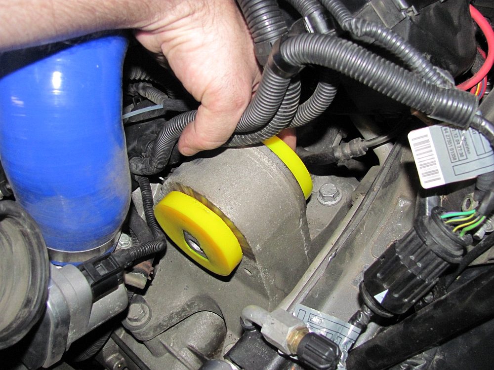
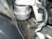
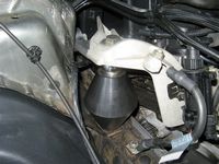
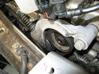
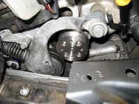
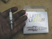
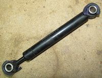
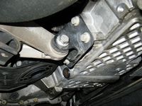
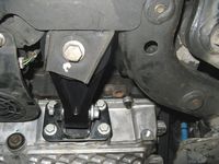
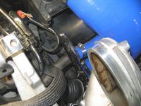
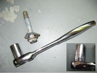
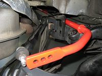
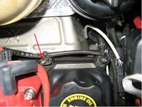
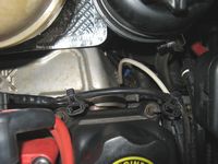
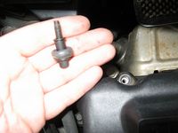
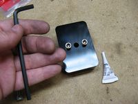
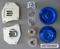
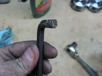
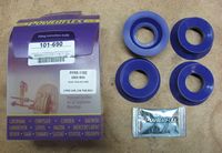
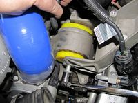
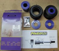
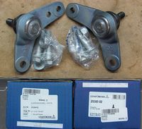
I needed a new upper motor mount to replace the failed/leaking OE oil filled mount, I knew this when I bought and made the deal on the car. In the search for a new mount, I came across the TSW Upper Motor Mount made of "Street" durometer poly and no oil to leak out and cause the mount to fail. These are the kind of parts I like to upgrade to when replacing OE, parts that will last longer and/or provide better performance. I found Way's business online when trying to locate a local Mini business that stocked these, I stopped by his place on the way in from out of town. Way is a great guy to talk to and knowledgeable when it comes to Minis- he races them so he knows a thing or two. I also bought his WMW Pulley Package which included a WMW 15% Pulley, NAPA Belt (P/N 060535-smaller for the new pulley), Colder Heat Range Plugs (NGK P/N BKR7EQUP replacing stock NGK BKR6EQUP, same as JCW), and a Detroit Tuned Tensioner Stop. I picked up a belt tool (to release tension in the tensioner to change the belt) and some Powerflex poly bushings (P/N 103-950) for the belt tensioner damper. I figured since I had to jack the motor up to install the new mount I should go ahead and do the pulley and associated parts installation at the same time
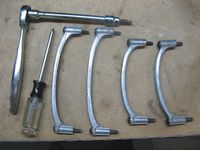
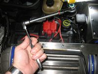
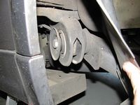
Way let me borrow the loaner pulley puller, the CravenSpeed one that does not require removing the tensioner assembly
The pulley makes a noticeable difference in the low end and I now have peace-of-mind knowing the new belt and tensioner damper bushings/stop are installed. The TSW mount feels a lot more solid than the OE upper mount, some minor NVH but nothing I would complain about.
My DIY guide for all of this can be found HERE, the TSW upper motor mount instructions can be found HERE, and the various pulley DIY guides are listed at the bottom of this page under DIY Guides- I used a little from all of these for my installation.


[UPDATE]
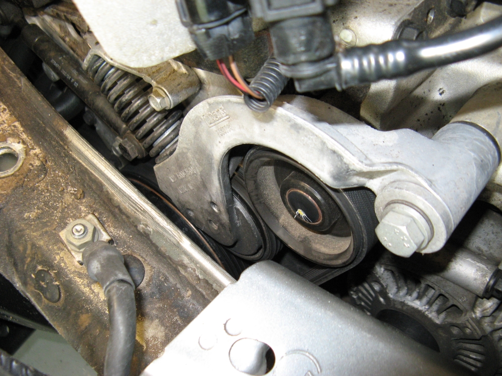
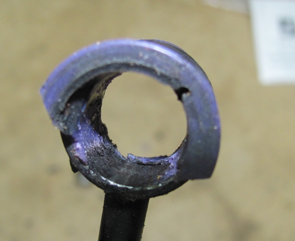
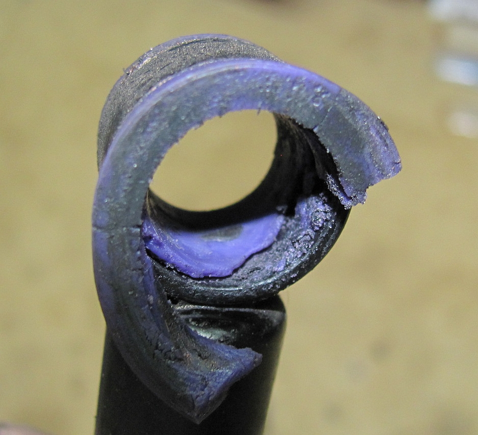
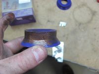
I discovered that with ~30k miles and about 8 months of use, the PowerFlex tensioner damper bushings were shot. I found on the NAM forums HERE and HERE that there was a manufacturing issue/defect for some of these and it was highly likely that I had gotten some of the bad batch. In my correspondence with PowerFlex USA I found that all of their bushings have a LIFETIME WARRANTY and that I should return these to Way to get a new set- which Way was quick to do, I picked them up the next day (THANKS WAY!). The material of the new bushings feels a good bit stiffer than the failed ones so hopefully these "correct" batch bushings will last.
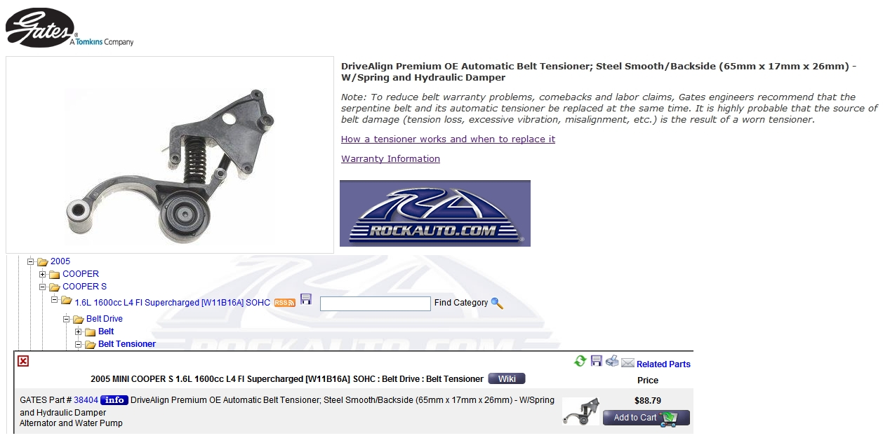
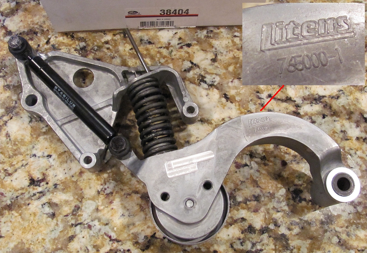
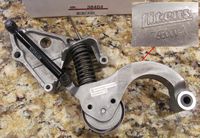
Before finding out the bushing replacement would be a quick turnaround, I looked into ordering a new tensioner assembly since the damper is not available separately. The best price I found was a Gates labeled tensioner assembly (P/N 38404) at Rock Auto for ~$100 shippedThis was about 25%-50% less than the other online prices I found. After it was delivered I opened the box to find the same OEM Litens tensioner that is on the car now, what a deal. I'll store it as a backup until I need it.


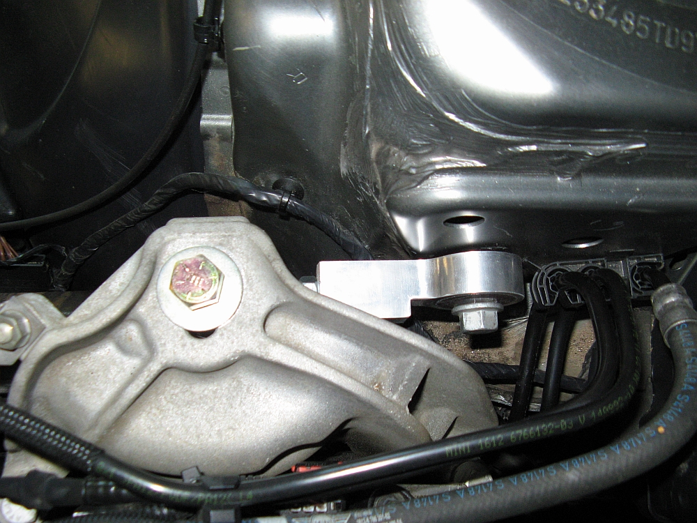
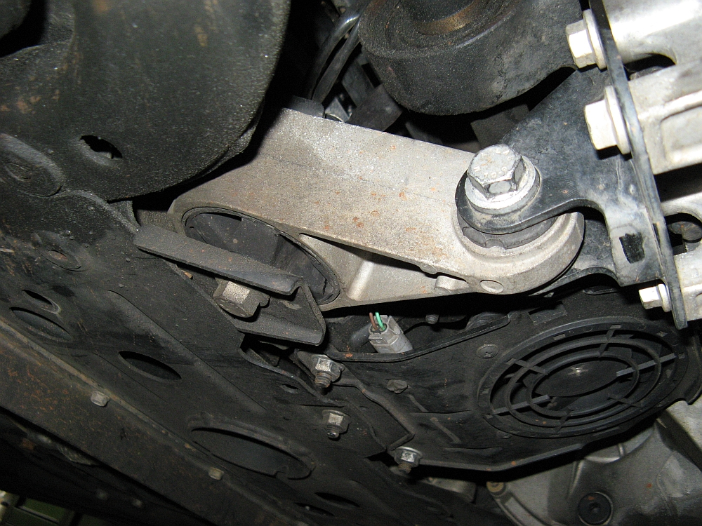
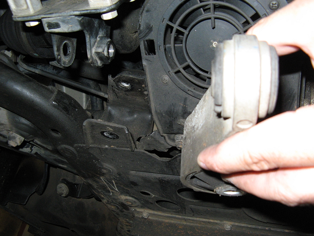
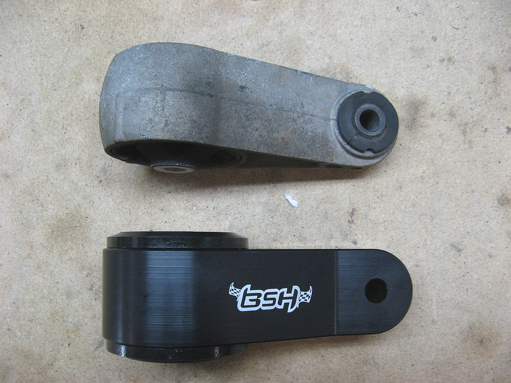
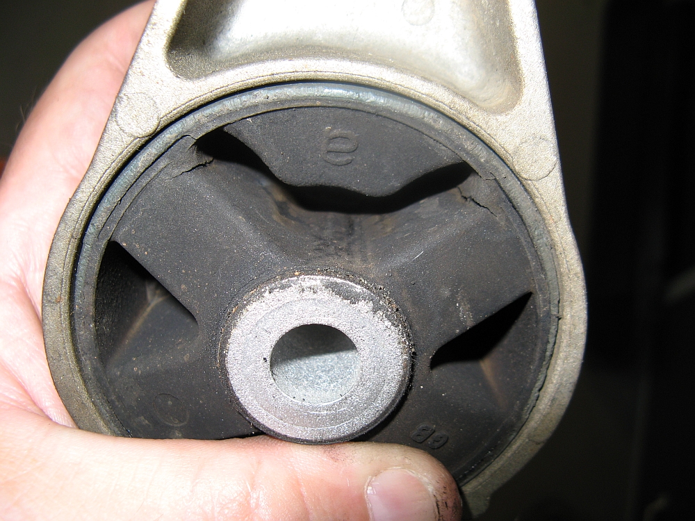
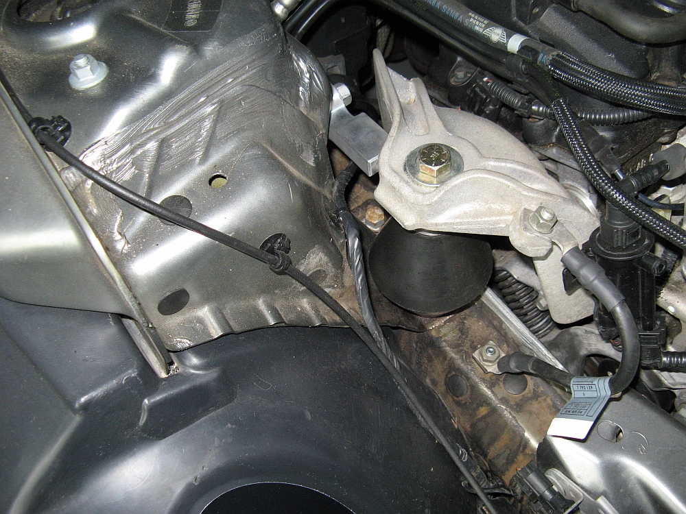
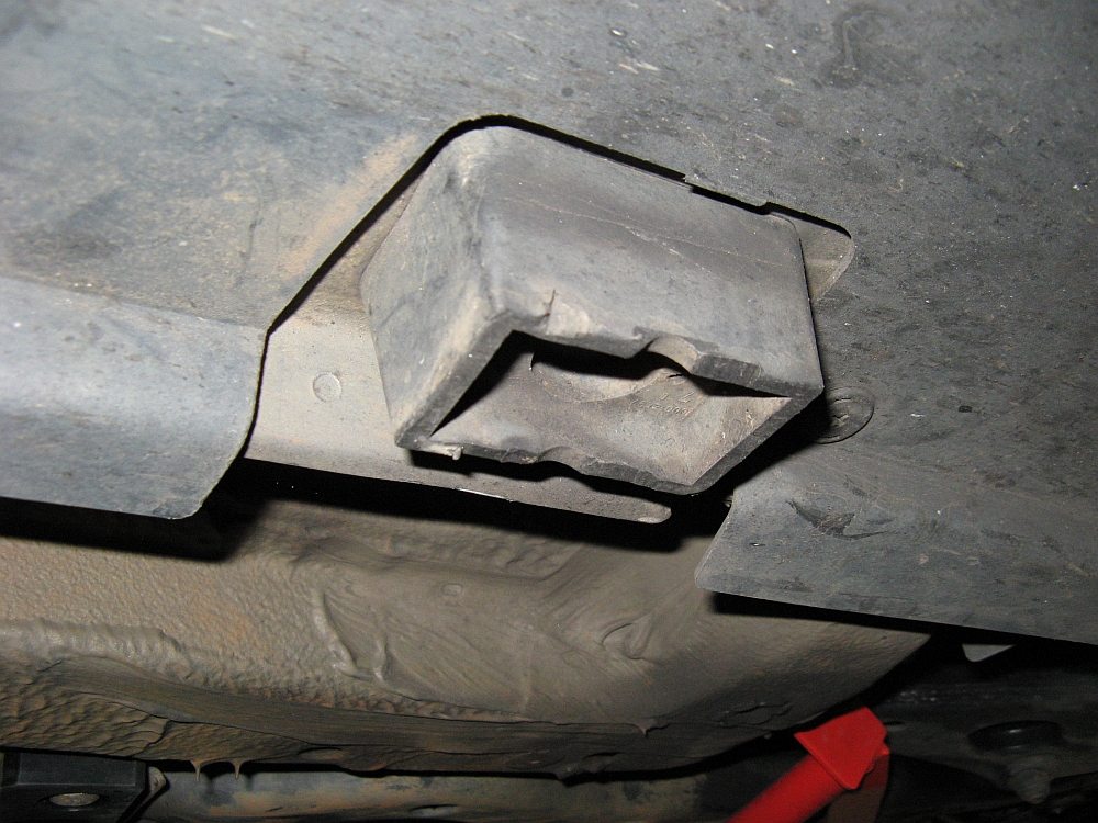
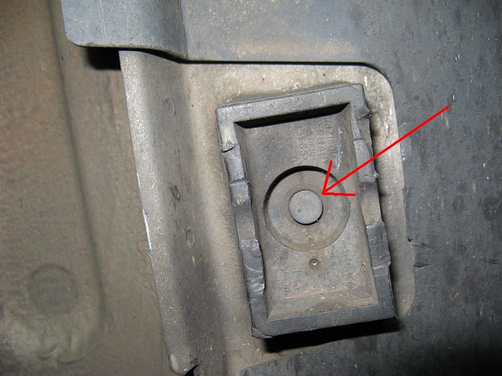
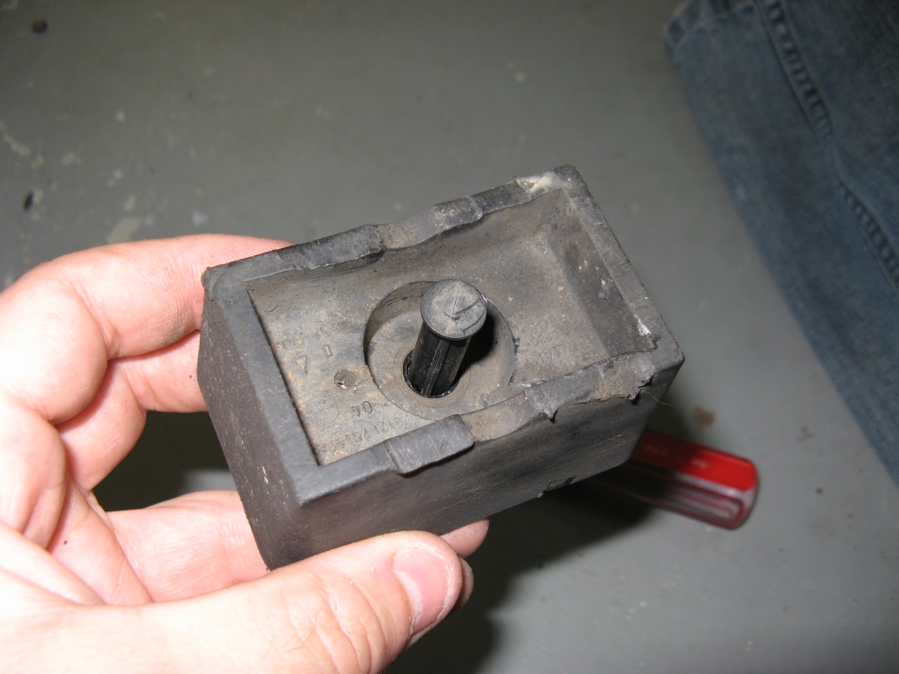
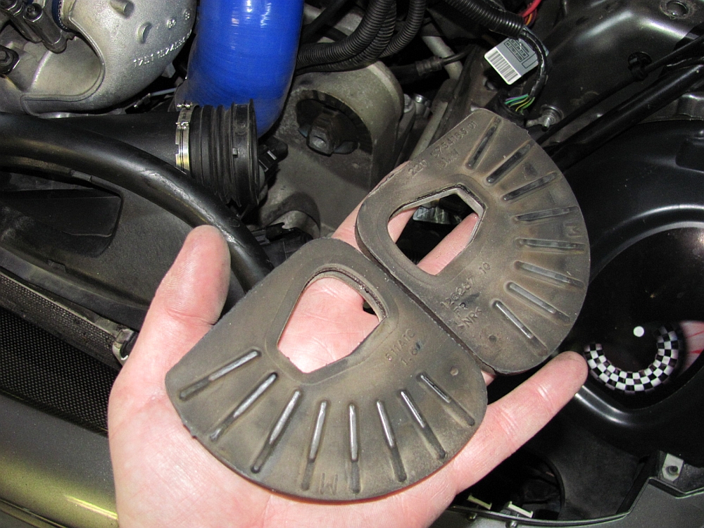
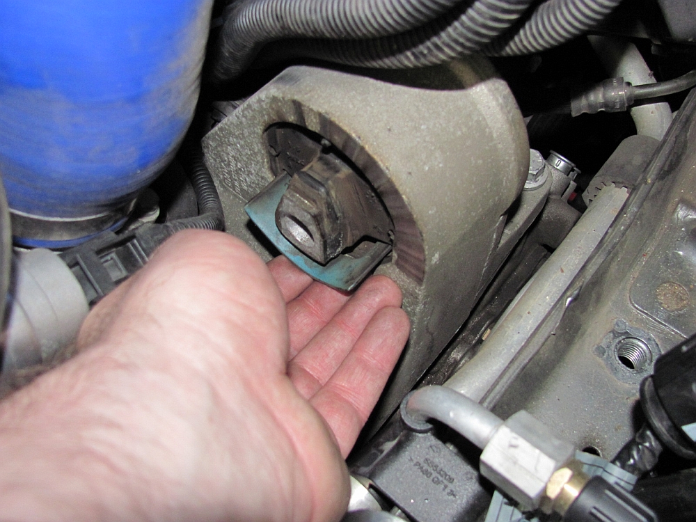
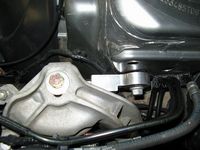
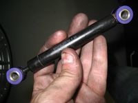
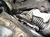
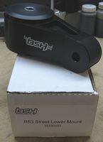
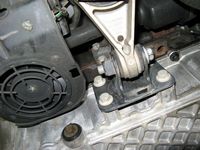
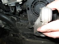
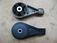
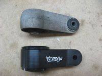
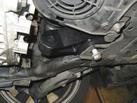
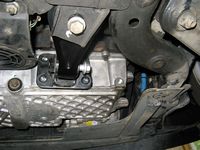
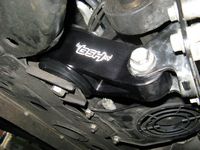
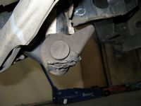
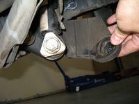
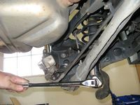
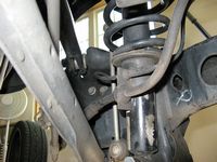
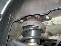
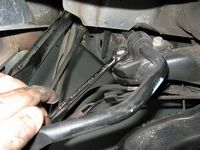
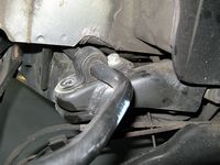
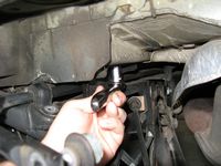
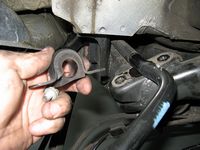
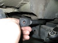
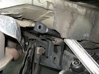
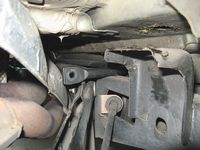
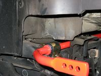
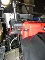
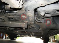
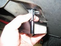
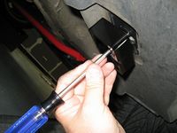
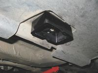
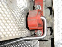
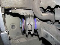
With the upper mount having been bad for an undetermined amount of time, I figured the lower mount had been taking the brunt of the motor movement and was likely bad as well. In anticipation of this, I went ahead and picked up the street version (durometer of 70A vs 88A for "Race") of the BSH lower mount (P/N 10330101) from Helix at MOTD. This mount eliminates bushing material at the trans mount end and has a significantly stiffer Delrin bushing at the firewall mount end. A little more NVH but nothing I would complain about (but several on NAM have) and a LOT more connection- shifts are SOLID now with not-a-lot of motor movement. If it is like other VF poly mounts I have used on other cars it should bed in after 1k miles or so and NVH will decrease, I will update this review then.
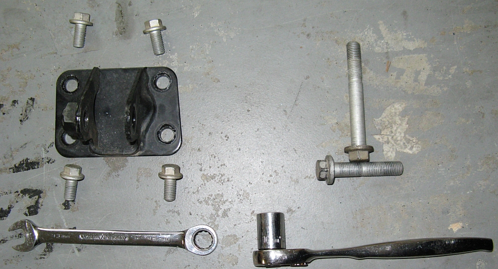
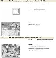
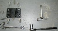
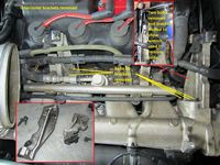
The lower mount is removed using a 16mm wrench on the larger bolts (2) that hold the mount in, and a 13mm wrench on the trans bracket bolts (4). I drove the car up on Rhino ramps before the R&R. The mount can be removed without removing the trans bracket but it is a bit harder to install the less compliant BSH mount- go ahead and make it easy, remove the four trans bracket bolts and bracket along with the mount. Installation starts by loosely starting the mount/firewall bracket bolt, then the mount/trans bracket bolt, and then the four small bolts that hold the trans bracket to the transmission. Starting the bolts may require moving the motor with one hand while starting with the other, it should be fairly easy to swing to the front or back. Once all are started they can be torqued to spec, starting with the (4) trans bracket bolts.
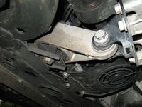
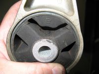
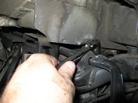
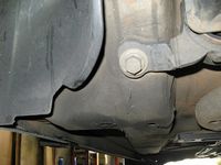
As speculated, the lower mount had started to tear (in addition to being soft) so it was due for replacement.

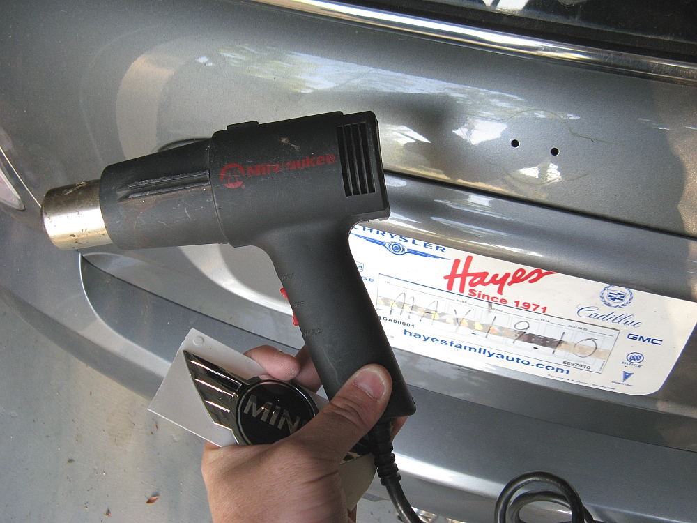
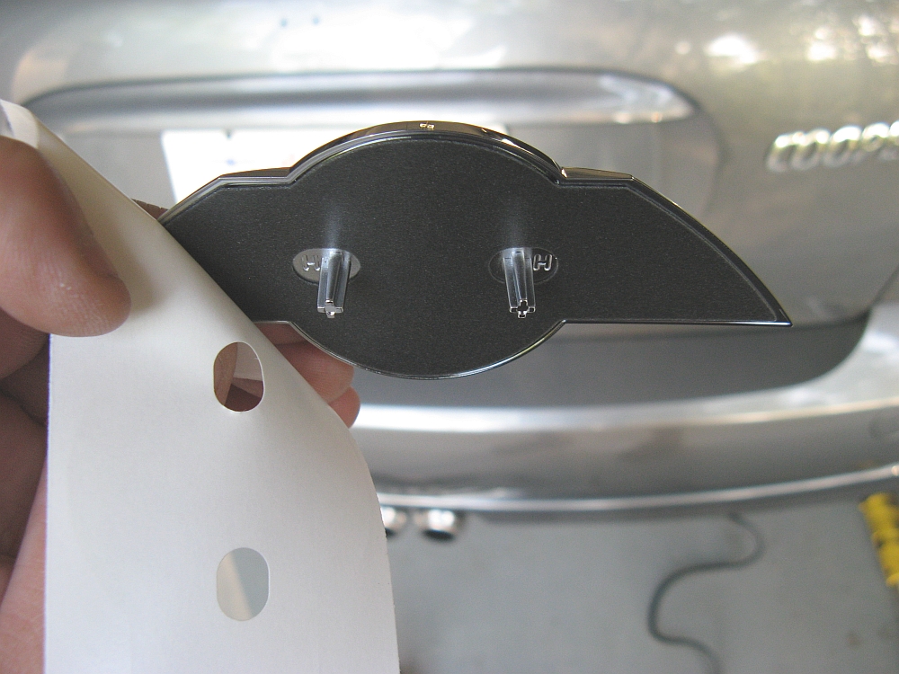
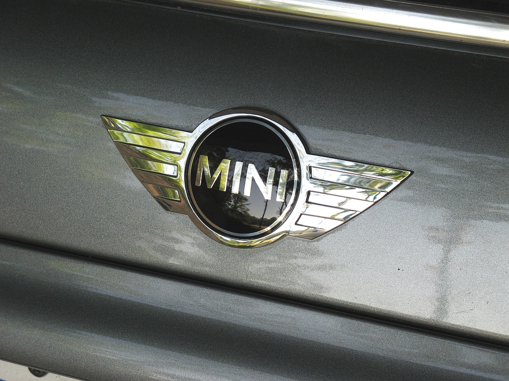
The Mini badge on the rear of the car (P/N 51147026186) had lost the clear coating and looked sad, so I replaced it with a new one from Classic Mini. Jayson is the NAM contact at Classic for discounted parts, phone 440-585-9950 or email bmwparts@driveclassic.com - ask for the North American Motoring forum discount (~20%).
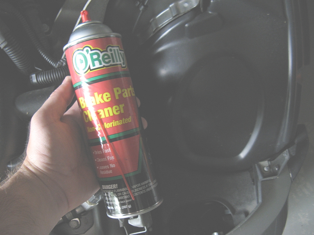
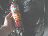
The old one was definitely stuck on good, in addition to the heat gun and blow dryer you may want to use some REAL dental floss to saw away at the tape under the emblem to release it. I used some brake cleaner to make sure all wax/grease/etc was removed so the new emblem would adhere well. The new emblem comes with double-sided tape, just align the pegs on the back with the holes in the hatch and apply light pressure to set the adhesive on the double-sided tape.


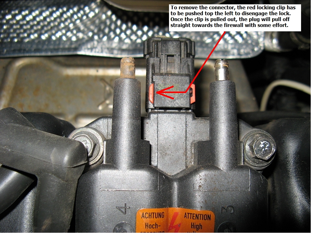
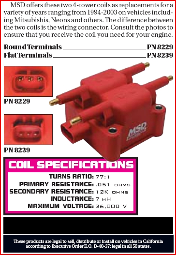
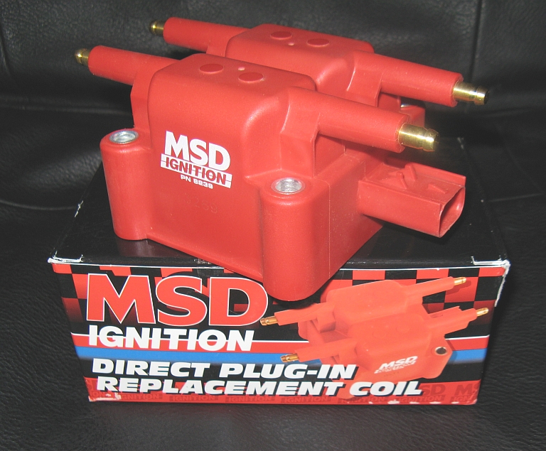
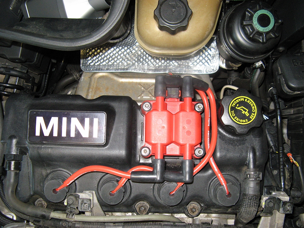
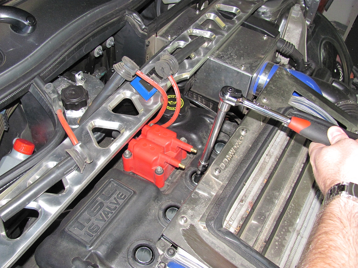
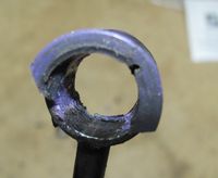
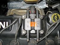
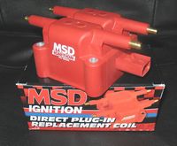
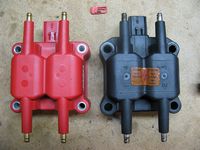
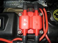
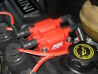
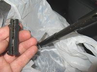
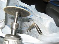
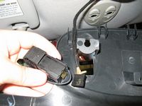
When I start thinking about buying a car, the first place I go is to the web forums to see what common issues are. One issue I found was with ignition coil corrosion. Typically this occurs on the #3 terminal, for me it was the #4. I used a Dremel to try and remove most of the corrosion and even had to use a small cutting disc to regrind the ridge on the pin, I figured this would work short-term (and actually used with no issues for a week or two). The wires were original and showed signs of boot deterioration so I ordered a new MSD coil (P/N 8239 for flat terminals, brass terminals so maybe better with corrosion) from Amazon.com (cheapest shipped price of $69.95, will say it does not fit Mini but it is the same coil you will buy for more money from a Mini vendor) and picked up some new Magnecor 8.5mm wires from Helix at MOTD.
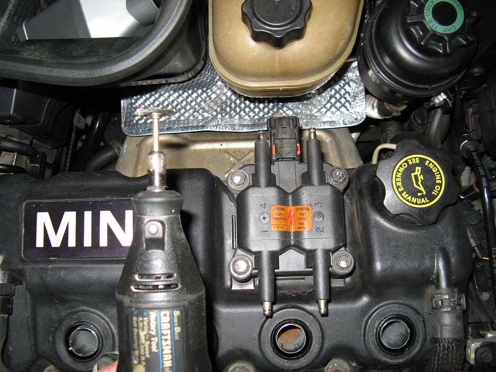
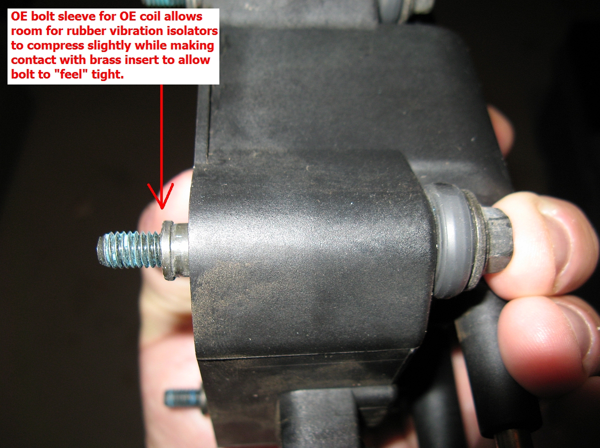
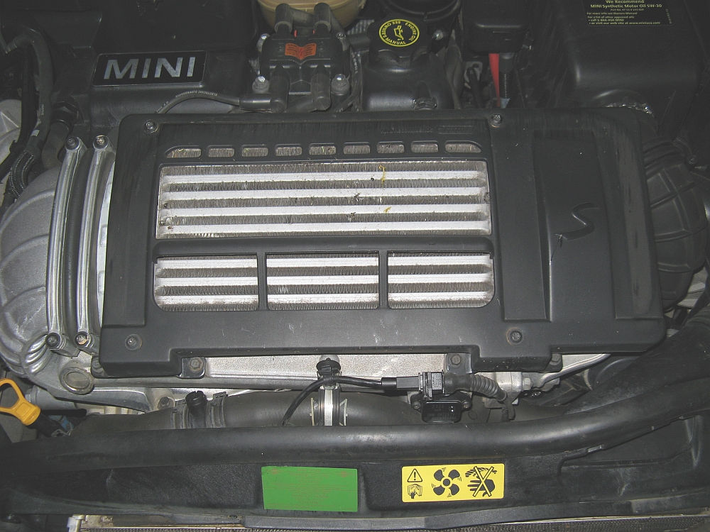
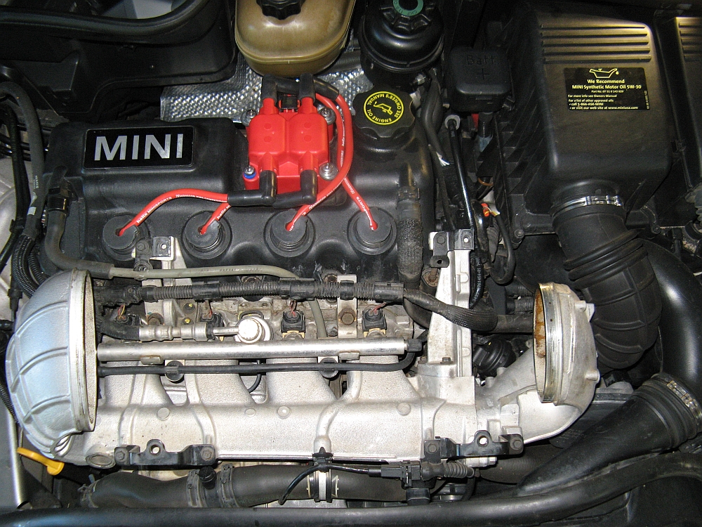
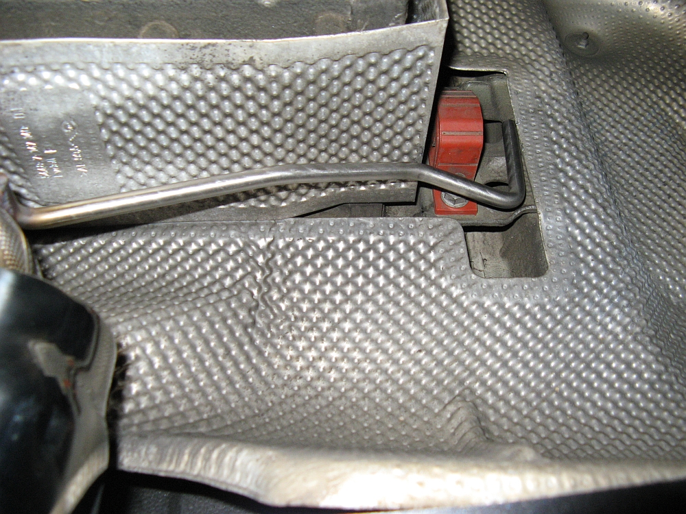
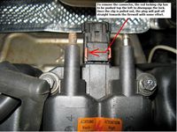
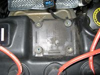
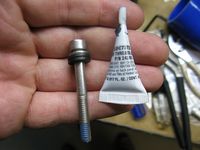
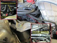
To easily access the spark plug wires for removal from the plugs, I removed the intercooler air diverter using a Torx 30 driver- 4 bolts, two short bolts on bottom and two longer ones up top. The cylinder order is simply 1-4 left to right and the coil order is 1-4 starting at the lower left and moving counter clockwise. If the coil is removed for cleaning or replacement and the plug has to be removed, the little red locking clip in the plug needs to be pushed toward the passenger side of the car (your left facing the motor) enough to disengage the locking mechanism or removed entirely from the plug- the plug is then removed by pulling it off towards the firewall with a little force. Note the orientation of the clip when removing, the ridge on the left side that you will use to pull it faces up. The MSD coil has other applications so it comes with no mounting hardware and also comes in a round and flat terminal version. Because the sleeves are in the MSD coil but also on the OE mounting bolts, rather than modify the MSD coil or the OE bolts, I sourced 4 Hex head stainless steel bolts (M6x1.00x50) at the local ACE Hardware and also got some stainless steel washers and a few rubber washers for each bolt. The OE coil had rubber spacers under the bolt heads for vibration isolation to some extent and I felt since I was not reusing these, the rubber washers might provide a little isolation from vibration. I used LokTite and was careful not to crank on these bolts, the brass inserts they screw into CAN be pulled out with force. The OE bolts somewhat alleviate this by their design which prevents over tightening- the sleeve around the OE bolts goes through the rubber base vibration isolators and is flush with the inserts preventing any airspace that the inserts could be pulled into and allowing the bolt to feel tight. So just a heads up, just snug them down and let the LokTite do its job. The OE rubber spacers were left in place for the base, I knew the bolts were tight enough when the rubber washers on top started to compress, since the bolt sleeve does not exist above/below the MSD coil, the bolts will not "feel" tight when they are where they need to be, this is an eyeball measurement. I may try to fabricate some spacers to replicate the added length of the OE sleeve so that the bolts are tight but allow the coil to float on the rubber isolators like OE.....
I felt that the car performed more consistently with the new coil and wires, but it probably would have done that with new OE parts too. But the parts installed were cheaper or not much more than new OE so......


I bought a few things at MOTD in the hour or so I was able to go hang out, one being the DDM Works Intercooler Diverter purchased at Way's tent, Way Motor Works. The installation was easy, remove OE intercooler diverter using Torx 30 driver (4 bolts, two short bolts on bottom and two longer ones up top) and install DDMW Intercooler Diverter. The supplied screws with washers are fed through the top and into the rubber washers provided and then installed using a Hex wrench. It looks better and the theory is sound....

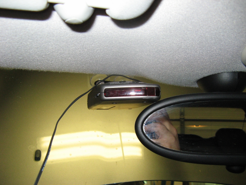
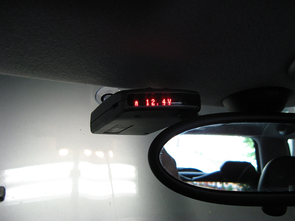
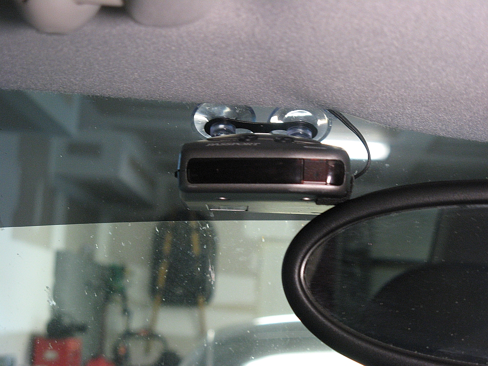
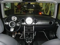
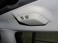
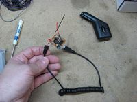
I got tired of the non-hard-wired radar detector, this is usually one of the first things I do when I get a new car. So, I ordered a direct wire adapter on eBay for $7 and decided to install it before heading back out of town. I installed the radar detector on the driver side of the rearview mirror, it is not in the way of the sun visor positioned there and the volume is a little louder- it can be hard to hear at interstate speeds with the windows down. I found that the detector bounces less if it rests on the rearview mirror, so I used some felt tape to eliminate noise and friction.
Passport 8500 X50 (manual HERE) is the current detector used, functions as voltage guage between alerts and is not easily noticed looking in from outside. Not quite as good as the V1s I have in the BMWs but I already had it and it works- just no arrows
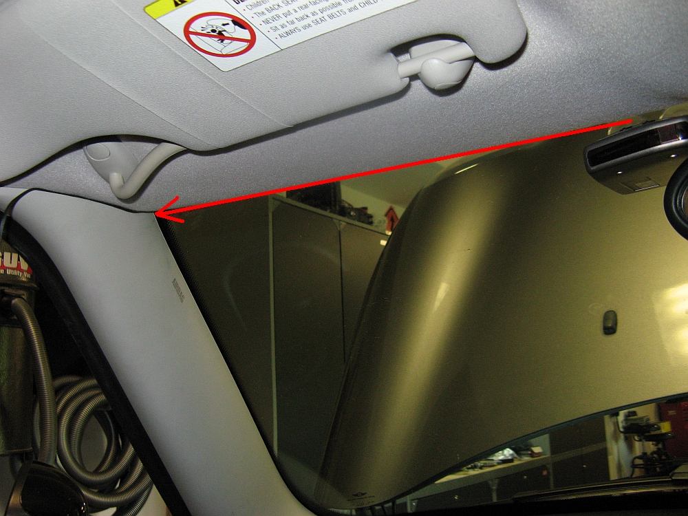
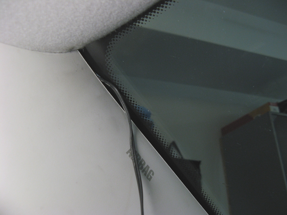
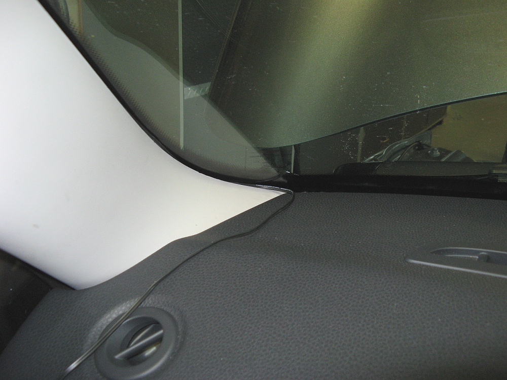
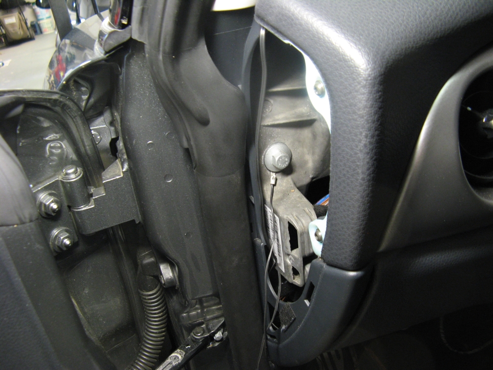
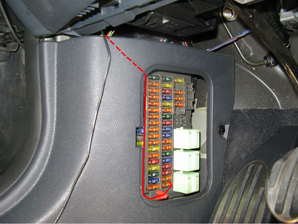
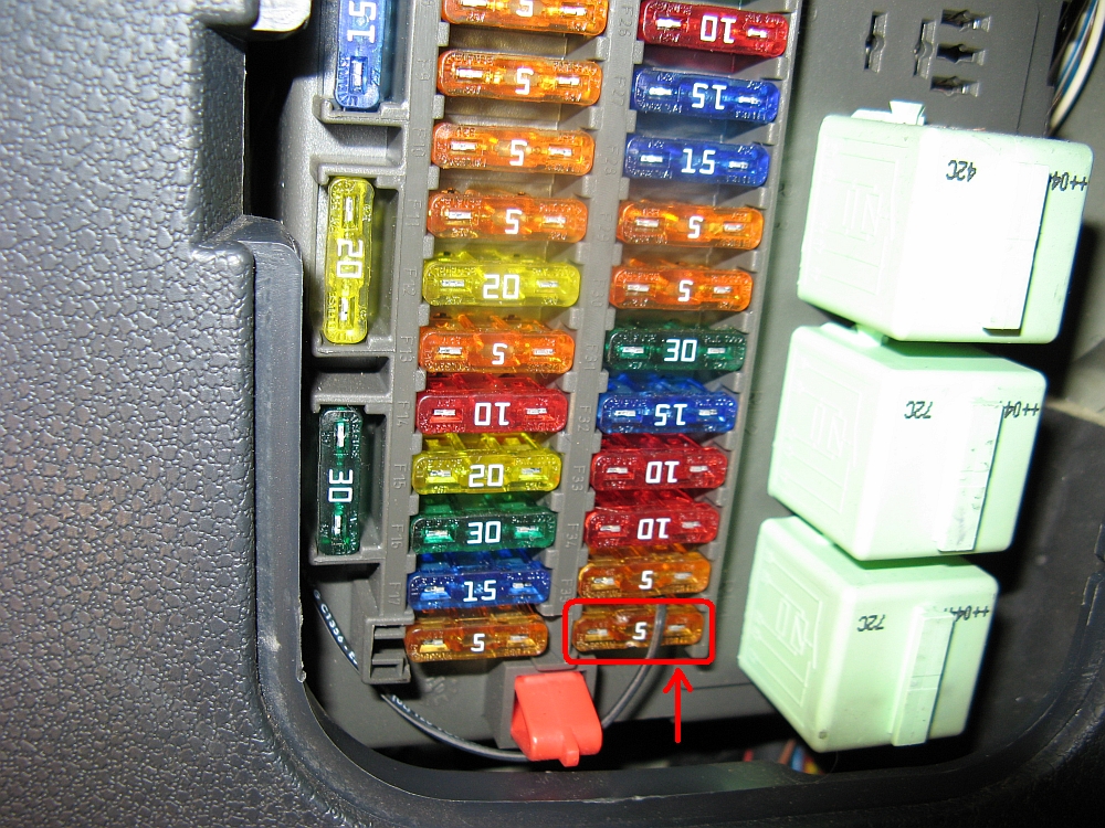
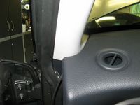
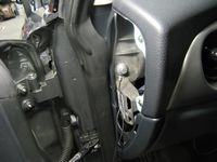
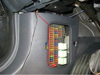
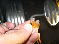
The power wire is run from the detector, across the top windshield trim, around and down the front of the a-pillar piece, and finally down to the fusebox tucking the wire behind and between trim pieces as I went. Since the wire was not fused, I used a volt/ohm meter to find that the left side of the fuse is the 12v side- I wrapped the 12v+ wire around the right spade of the fuse and plugged it back into the fusebox (this is what we did before someone invented fusetaps). Now the detector shares the same fused circuit as the defroster (lowest right corner 5A fuse looking at the fusebox). The ground wire was tucked under a bolt under the driver side access panel on the way down to the fusebox. This fuse position only powers the detector when the car is running and not when key is just in the accessory position.
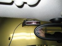

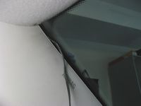
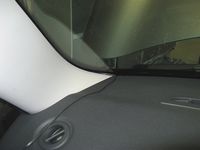


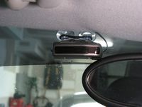
Windows Tinted 35% by Mr. Tint (aka Barry Wood, H:(770)963-7924 C:(404)392-8007). The tint strip at the top of the windshield helps conceal the radar detector located there:


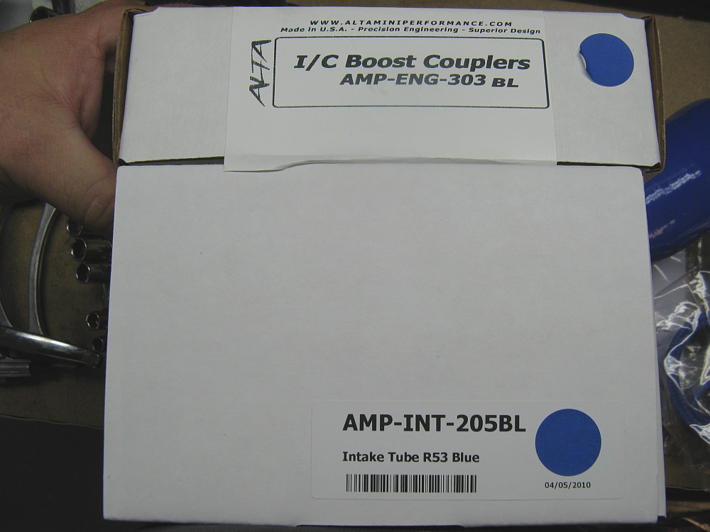
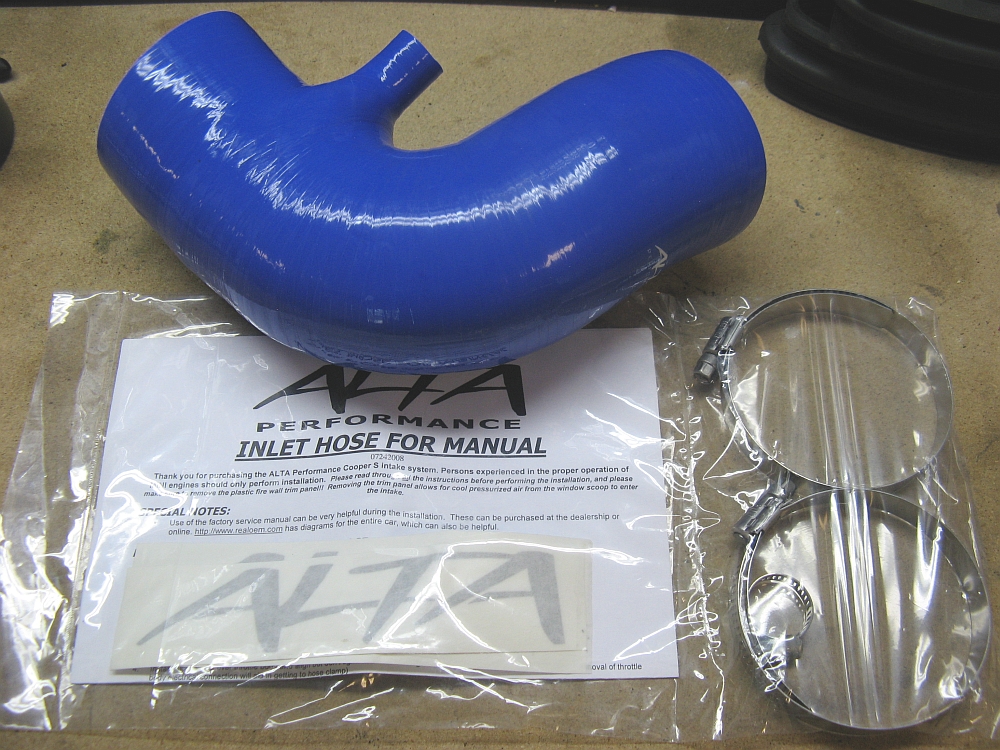
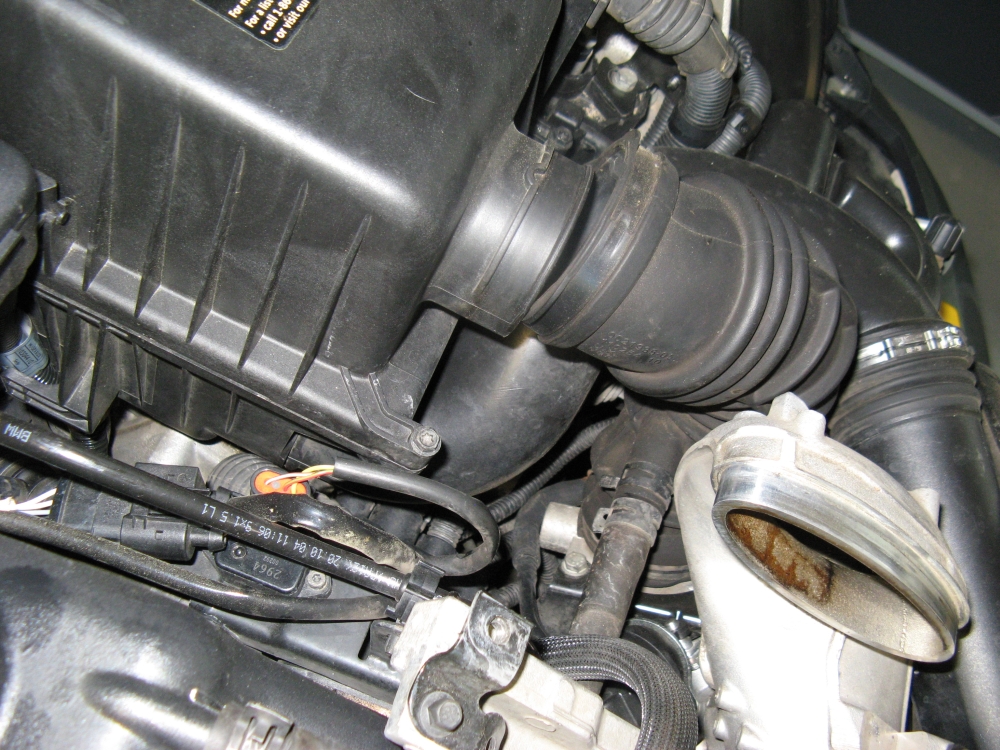
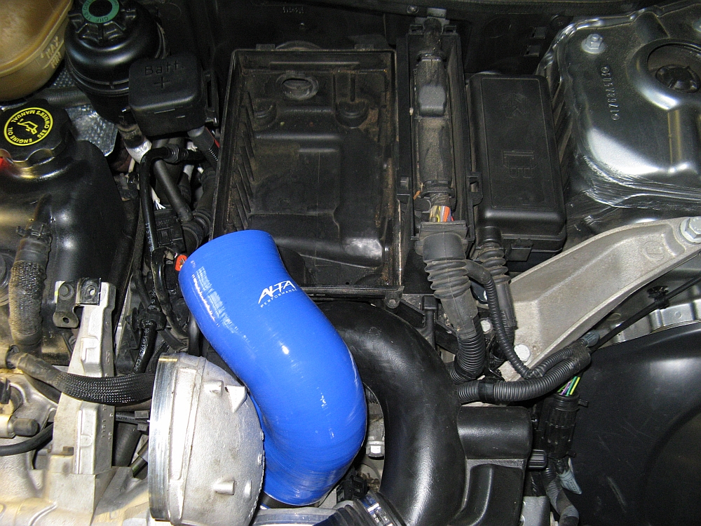
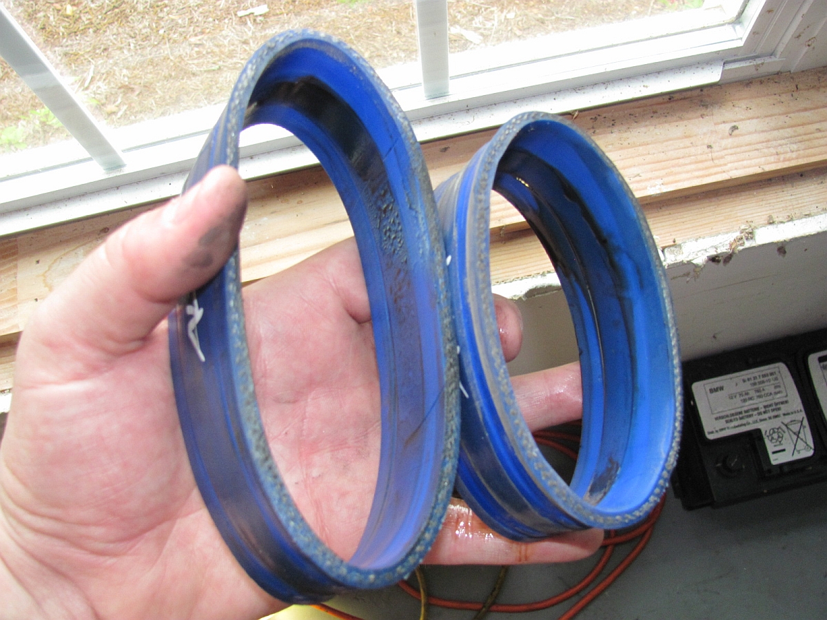
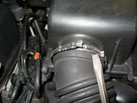
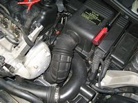
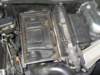
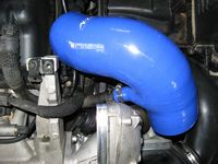
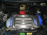
Alta Performance Intake Silicone Hose (Blue) and Alta Performance Intercooler Silicone Couplers (Blue) installed, purchased at North American Motorsports.
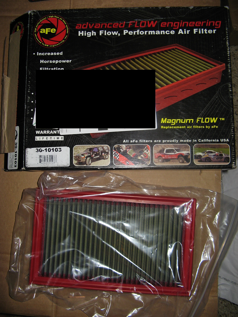
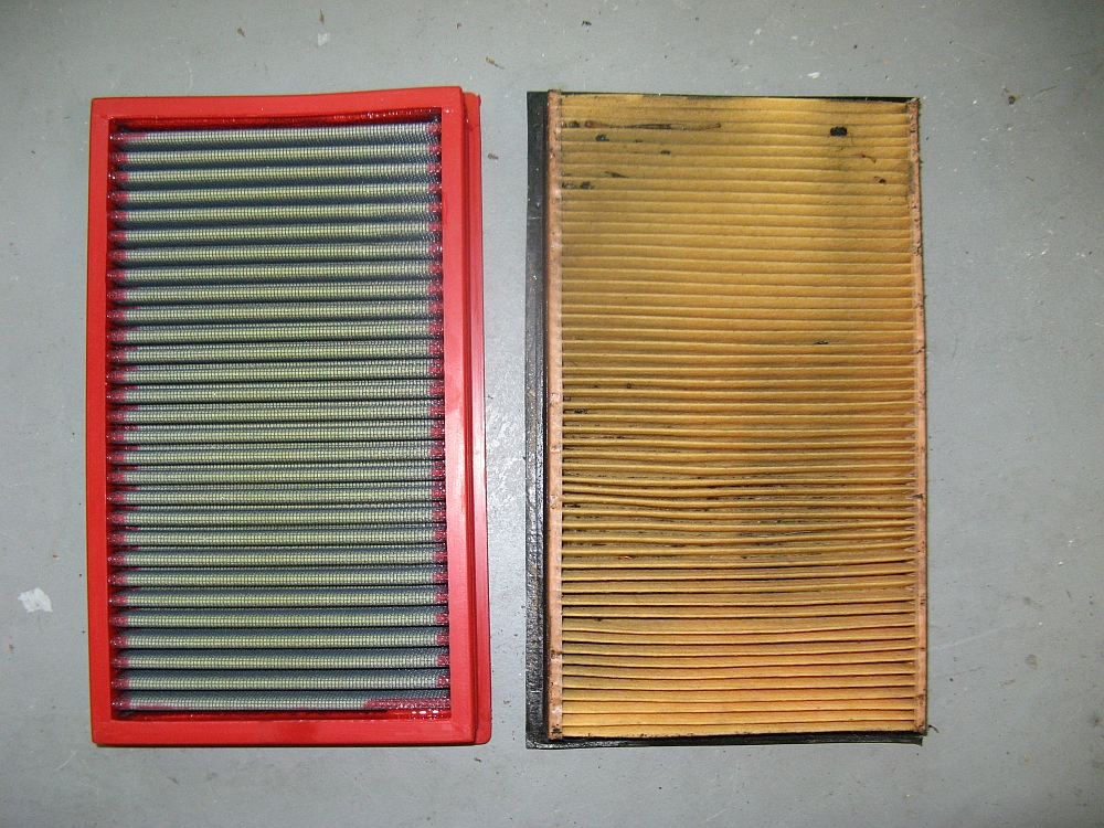
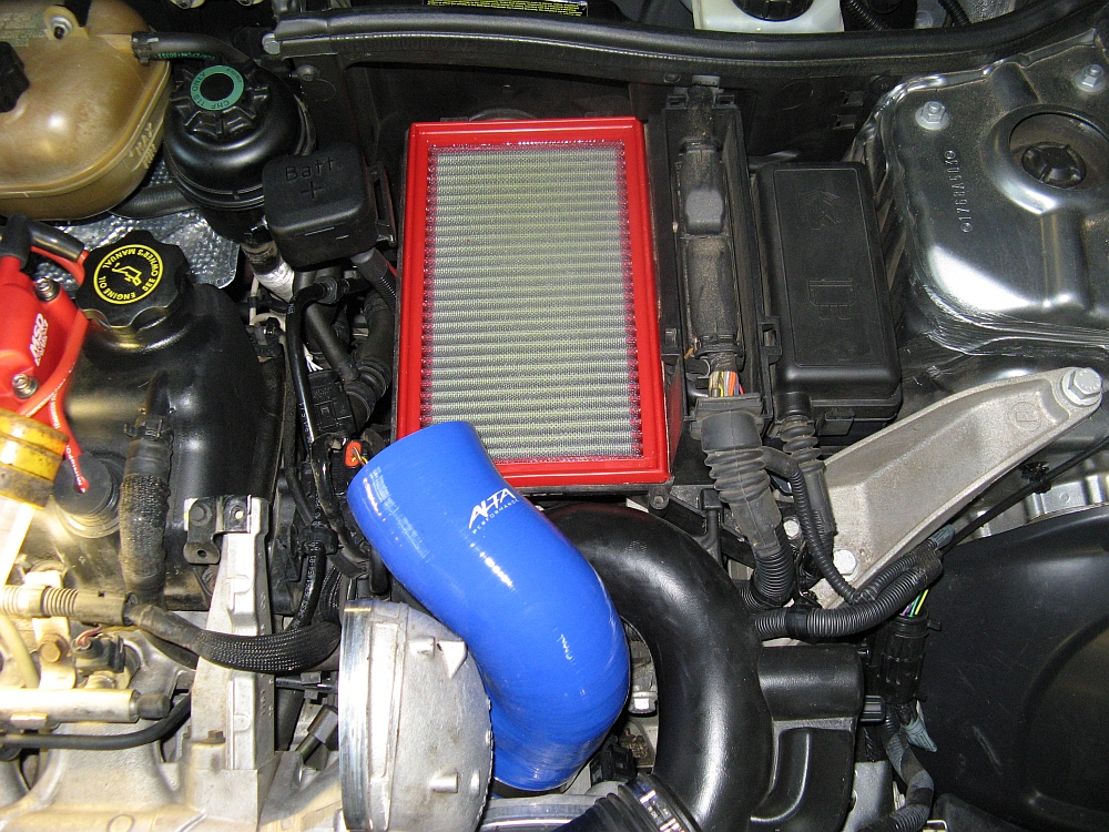
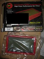
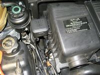
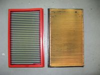
It also seemed like a good time to install a drop-in aFe air filter (P/N 30-10103) for the OE airbox.
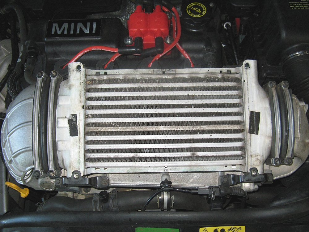
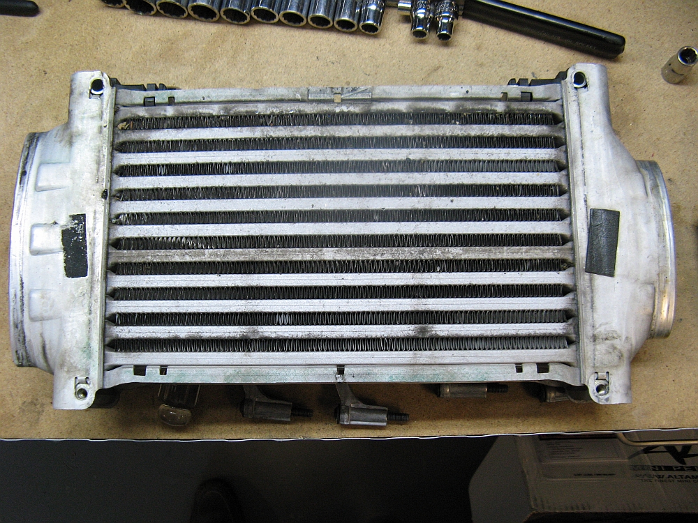
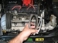
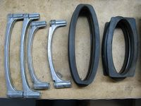
The intercooler frame/air diverter is removed (4 T30 Torx screws). The rubber bellows that hold the intercooler to the air horns are removed next, also 4 T30 Torx head screws for the bellows clamps. Once the clamps are removed the intercooler can be pulled out of the larger bellows and then the smaller bellows and removed.
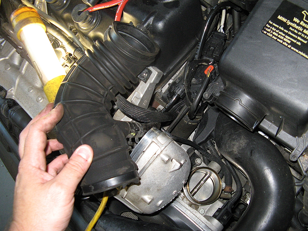
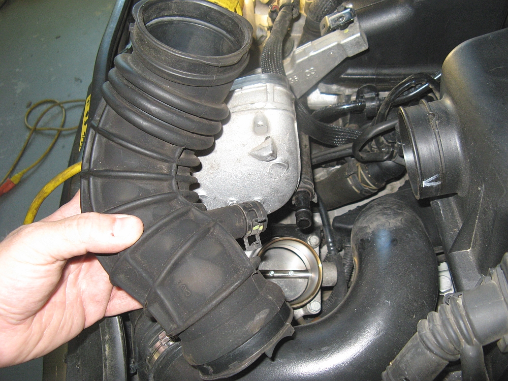
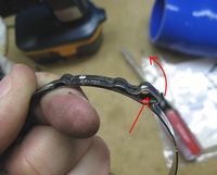
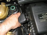
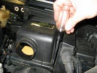
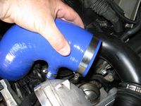
With the intercooler removed the intake hose is easily accessed. I used a flat blade screwdriver to pry apart the factory press clamps, just insert in the gap and twist. Once the top clamp was removed, the bottom was next. It may take a longer screwdriver to reach/remove this one. With both ends of the intake hose free, it is easy to flip the hose up and on its side to access the smaller hose clamp, removed with a pair of pliers. Installing the hose is easy to do in reverse order after the filter has been installed.
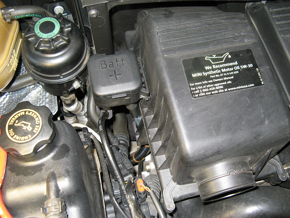
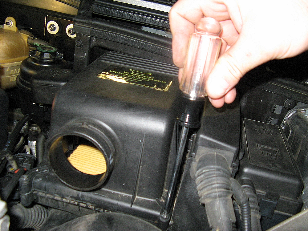
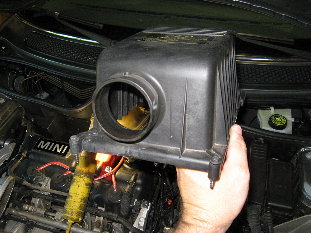
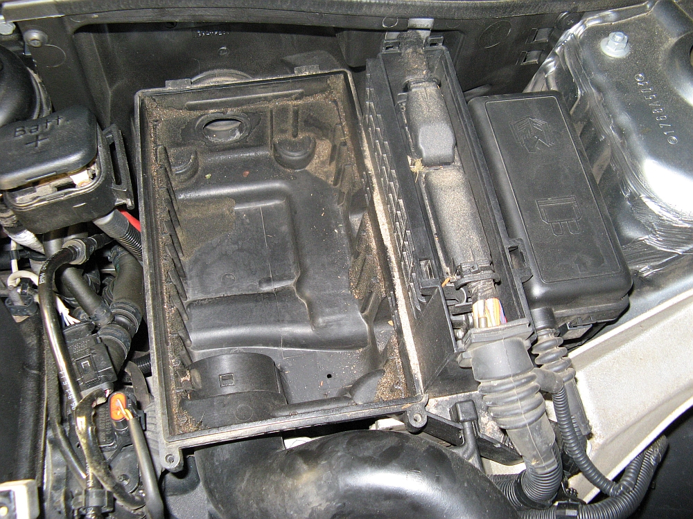
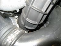
There are two Torx head screws that hold the airbox lid on, after these are removed (and the battery wire holder also pulled up/out and to the side) the lid is tilted back/up and removed. The old filter lifts up and out. This is a good opportunity to use a shop vac to get all of the dirt/leaves/debris out of the airbox before installing the new filter and the airbox lid. When installing the new intake hose I found that the smallest hose with new supplied clamp could be installed first, and then the lower clamp- both of these bolts are easily reached and tightened with a ratchet/socket with the IC removed. The upper part of the hose did not line up perfectly with the airbox so I held it in place while tightening the upper clamp.
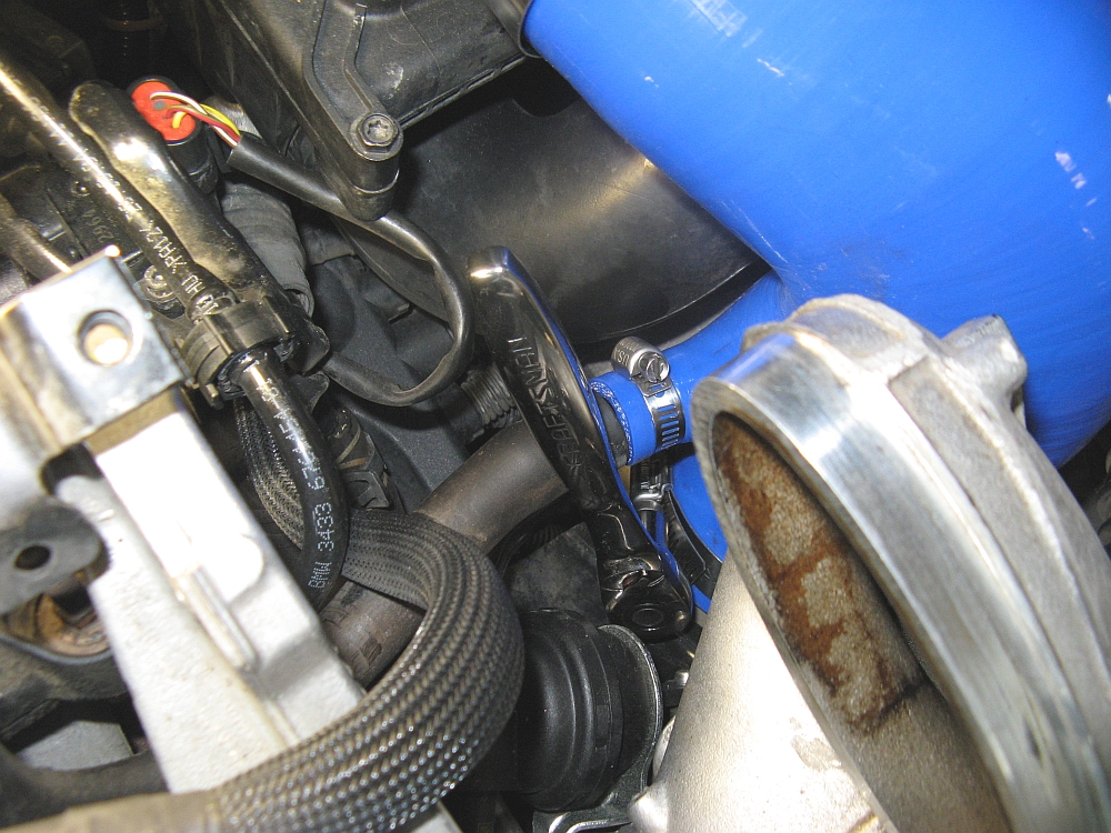
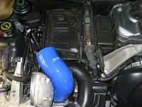
Once the new silicone intake hose and air filter are installed, the intercooler can be reinstalled with the new silicone couplers. I tried this a few different ways and found the best was to seat the smaller side of the intercooler FIRST and then the larger side LAST. When installing the clamps, be sure they are tight, if they are loose or leaking they can be made tighter by removing some material with a small file on both the male and female opposing sides of the clamp- I did not have to do this with mine as they were tight.
With it all back together it feels better, looks better, and might have gained 1HP on the dyno.....but mods are what I enjoy doing, and these silicone hoses should last a long time.


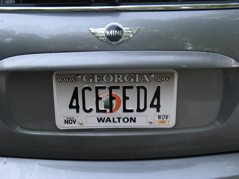
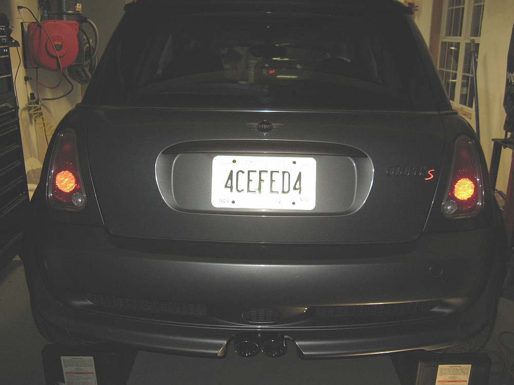
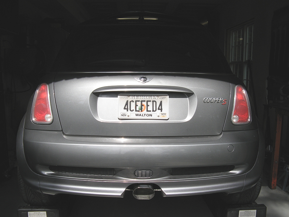
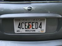
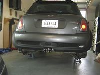
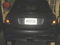
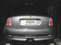
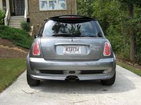
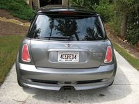
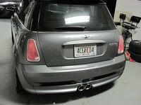
Old license plate taken out of retirement....4CEFED4 (Read Force Fed Four Cylinder)
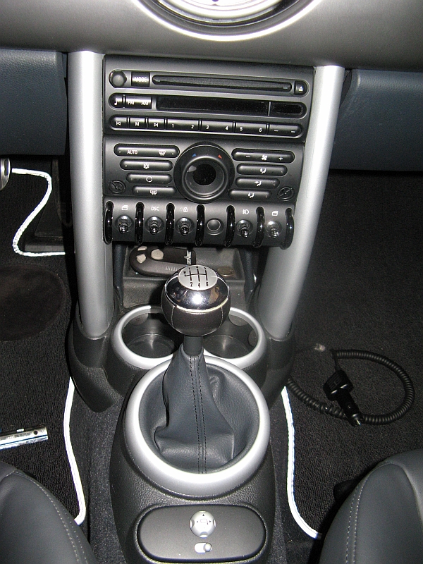
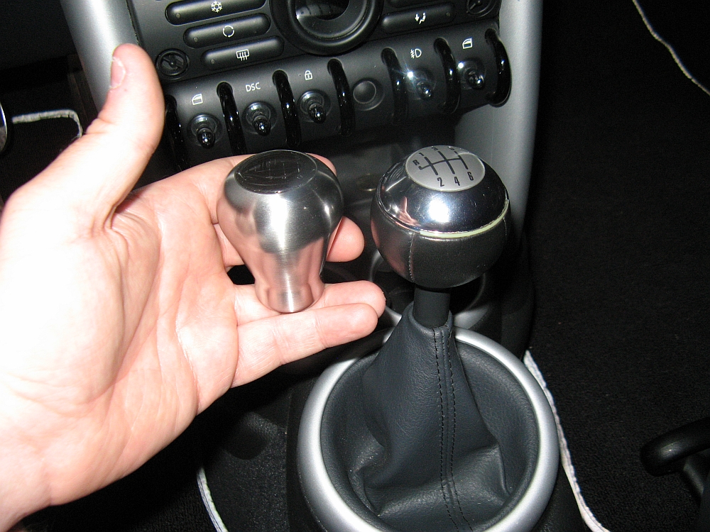
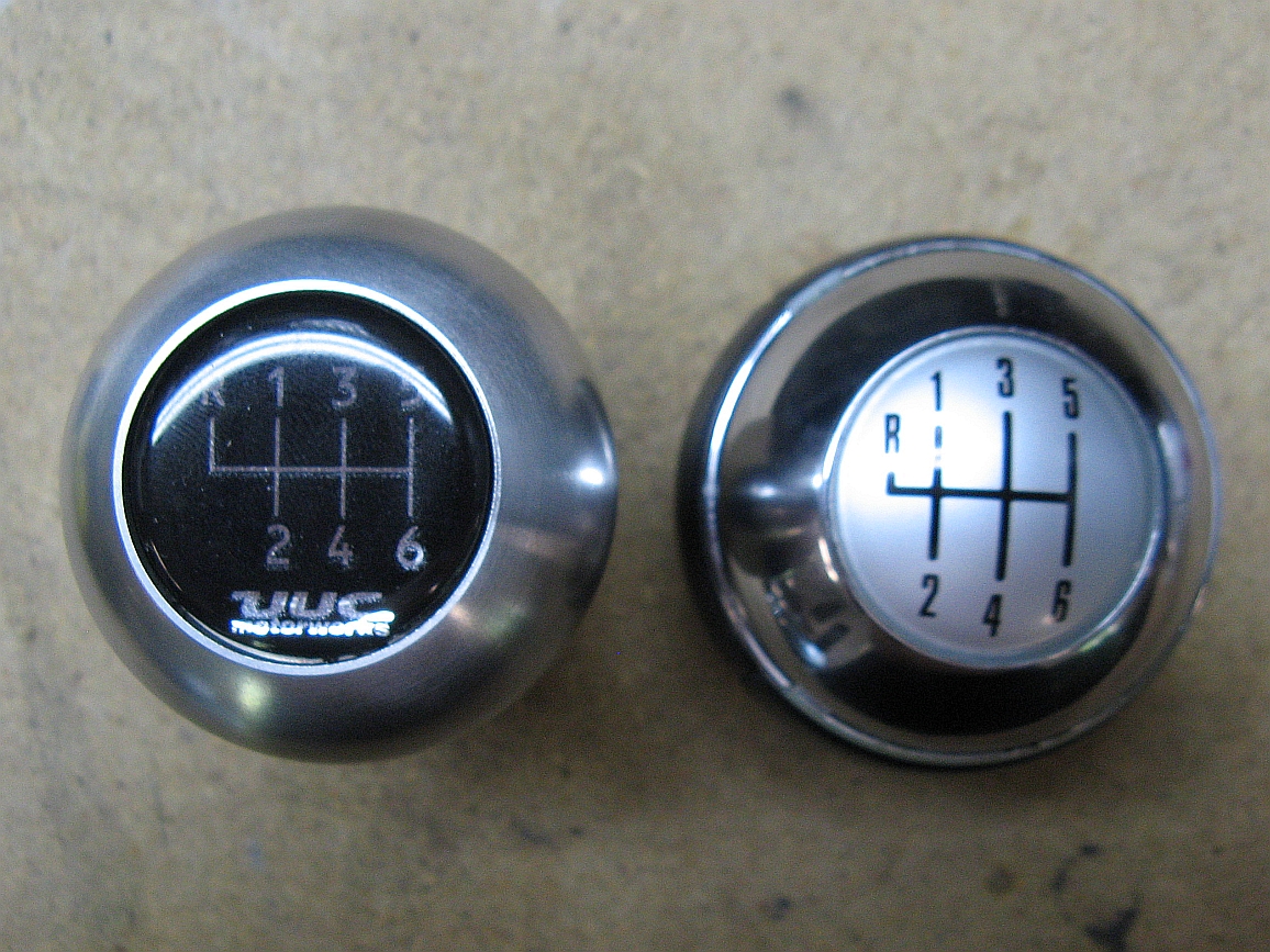
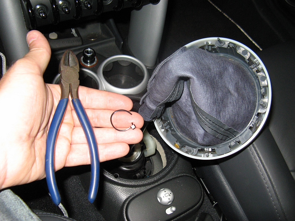
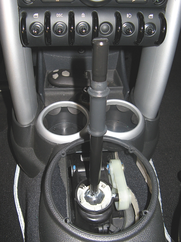
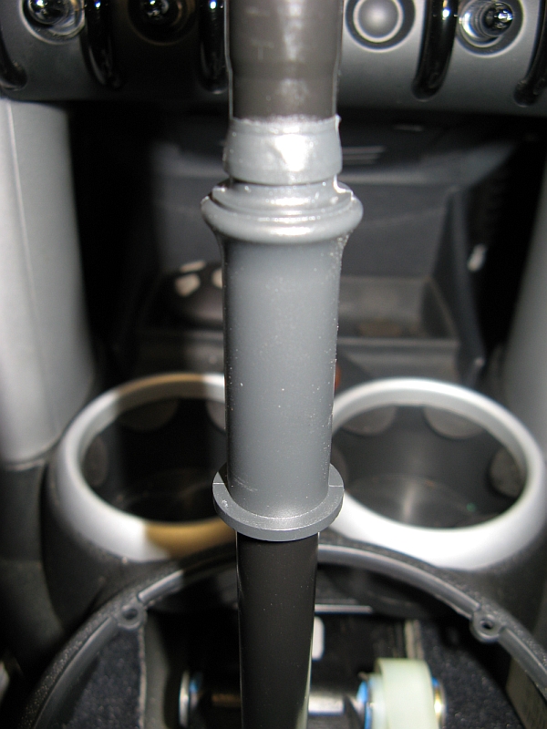
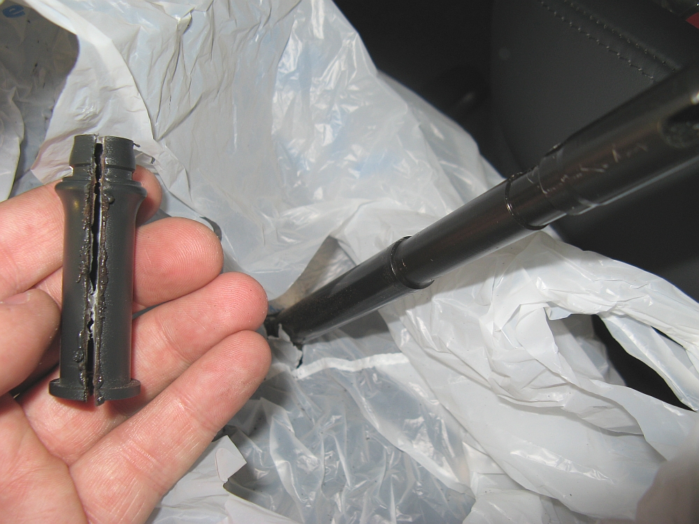
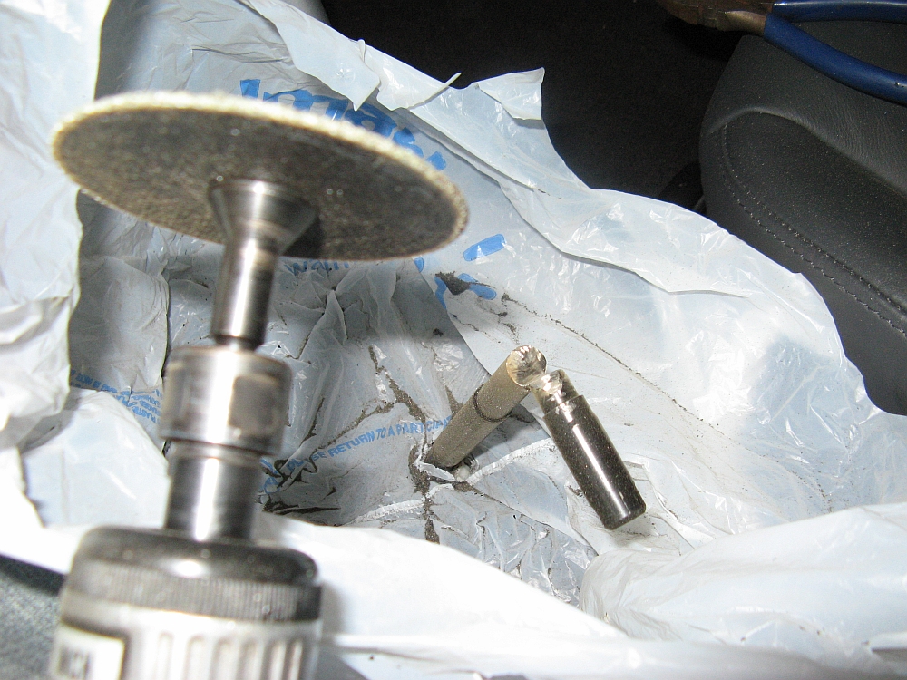
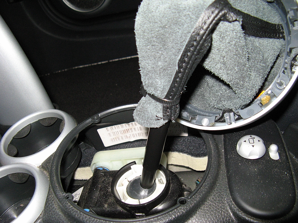
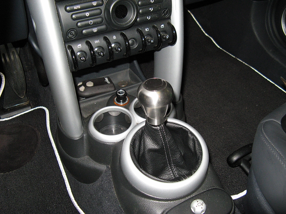
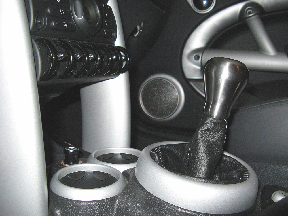
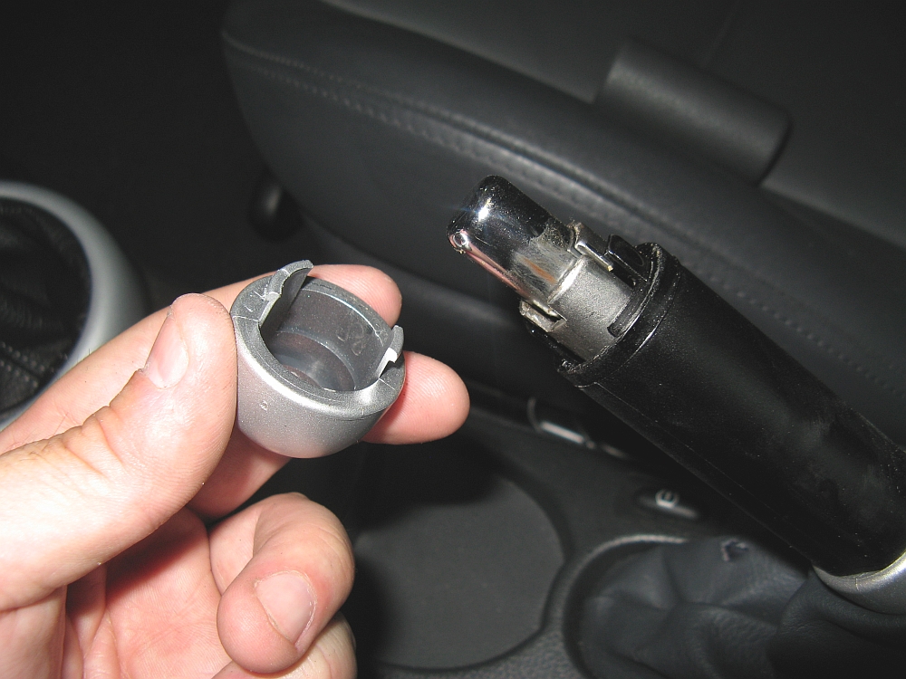
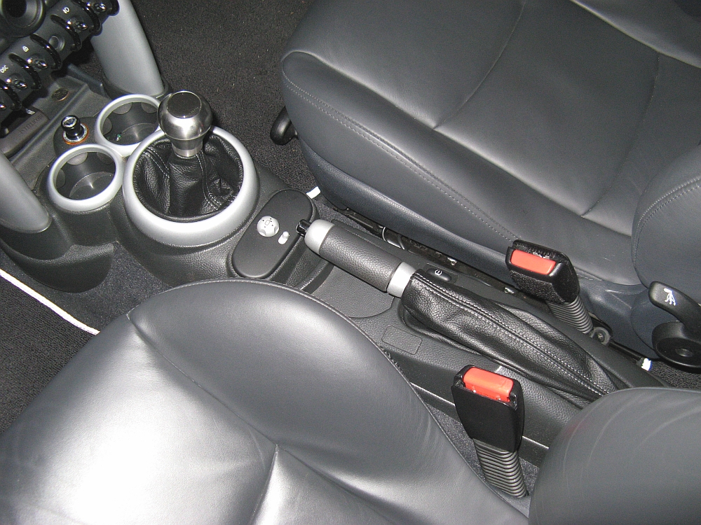
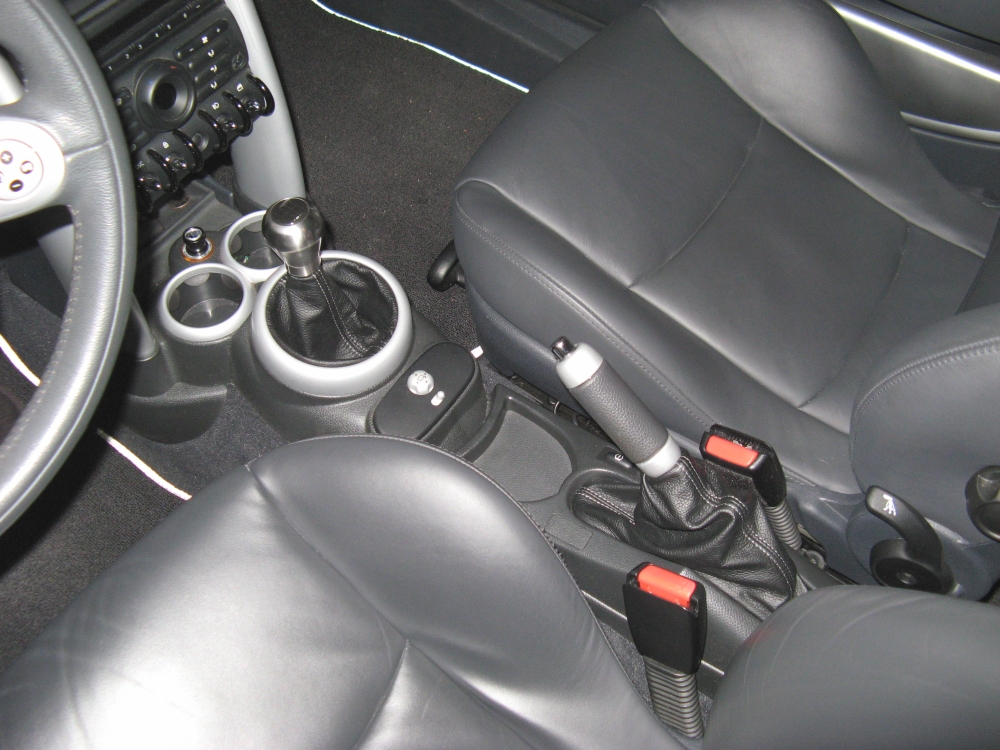
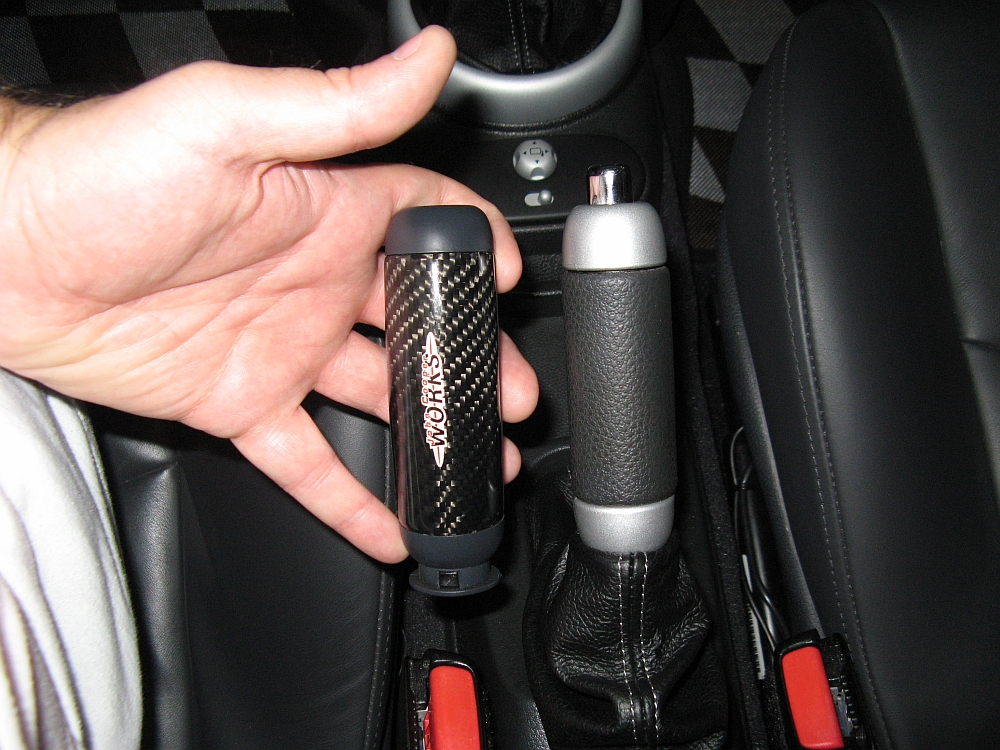
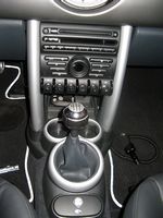
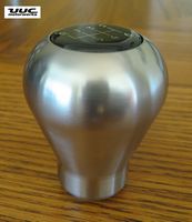
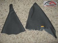
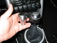
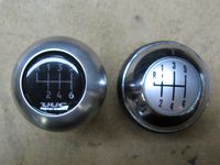
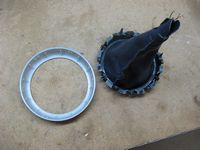
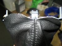
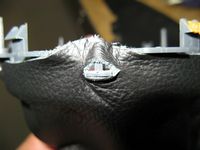
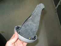
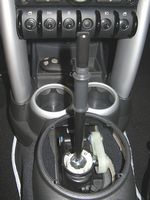
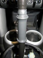
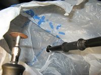
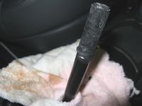
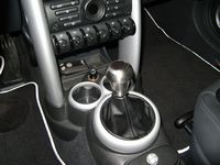
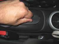
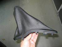
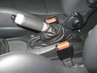
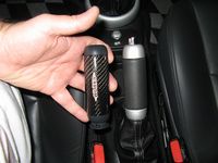
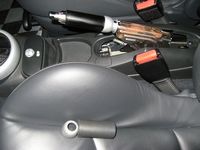
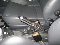
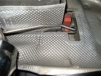
RK3 shift knob from UUC Motorwerks (archived ad/details HERE) and shifter/hand brake boots from Redline Goods installed. I didn't care for the shifter height/throws so I decided to shorten it a bit, about 1.75". The plastic chrome on the OE knob was worn a bit so this was a good excuse to source a new knob from UUC- this also worked with my approach to shortening the shifter since the UUC knob relies on a hex screw (2.5 mm HEX wrench to install) to hold it in place and not the OE retention system. I waited a while for this knob and it seems that it is NLA even though I was able to place an order for it on the UUC website, Arjun was able to dig one up for me though after I contacted him (Thanks Arjun!). Surprisingly, the OE shift knob is weighted but just a little less than the RK3's ~22 ounces.
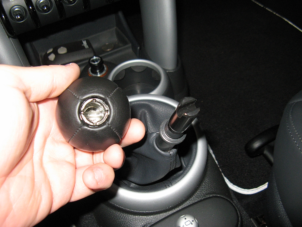
The OE knob is removed with some upward force, I usually put the shifter into 4th gear and pull up/back- be careful not to hit yourself in the face/head with the knob
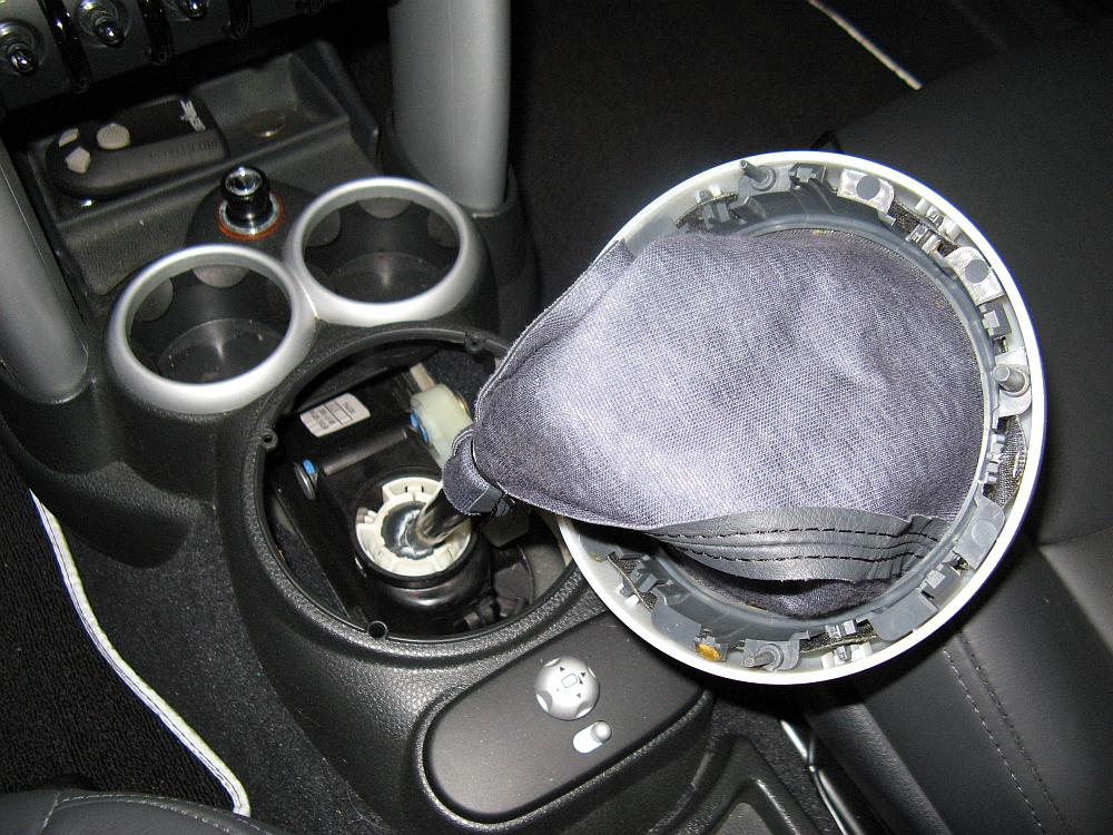
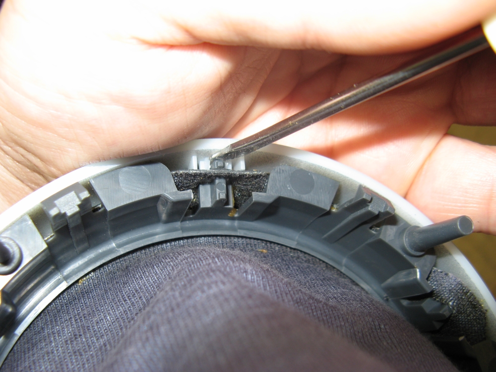
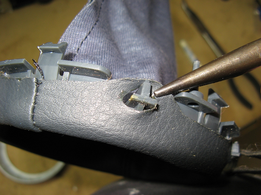
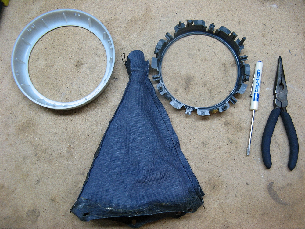
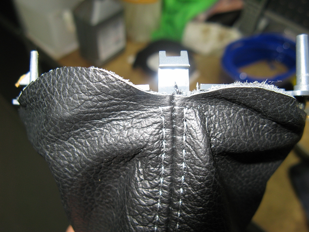
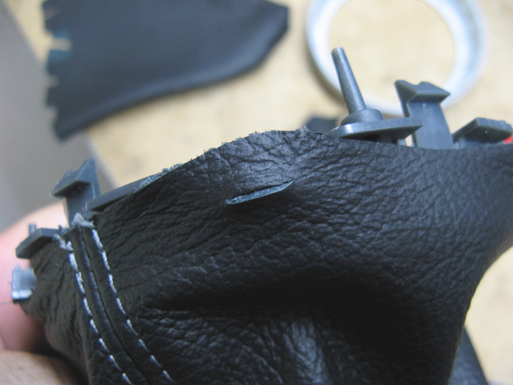
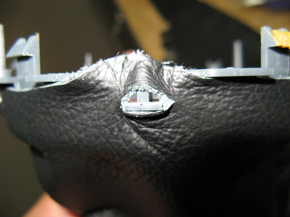
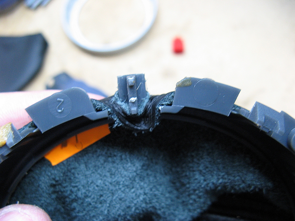
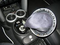
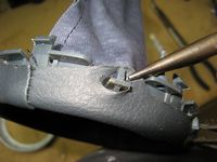
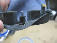
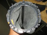
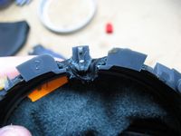
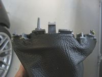
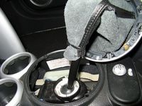
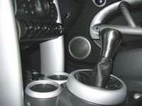
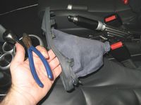
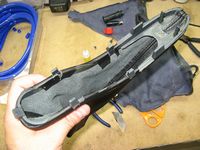
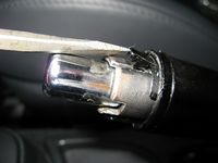
The shifter boot is attached to the base which snaps into the center console, a zip tie hold it to the shifter. This piece has four locator pins so it is important to line these up when snapping it back in. The boot is held to the base by having points around the boot stretched over retaining clips in between two pieces of the base and somewhat glued. The zip tie is cut off and the boot and shifter base are removed. The base pieces can be carefully seperated by pushing the outer ring (or using a flat blade screwdriver) to allow the inner piece to seperate, the shift boot can then be removed (I used needle nose pliers). Note the orientation of the boot on the base prior to removing and make reference front/back marks marks if needed- you don't want the new boot attached to find it is not the way you want it. The new boot will have to have holes cut in it to attach to the base, this can be done with a new sharp razor blade or Xacto knife using the old boot for reference. I used quick-dry SuperGlue to attach the boot to the inner ring in between mouting holes, it has been my glue of choice in the past. Once the boot has been attached to the inner ring, the outer ring can be carefully snapped back on. The boot is turned inside out and a new zip tie is used to secure it to the shifter. The base is then carefully snapped back into the center console.
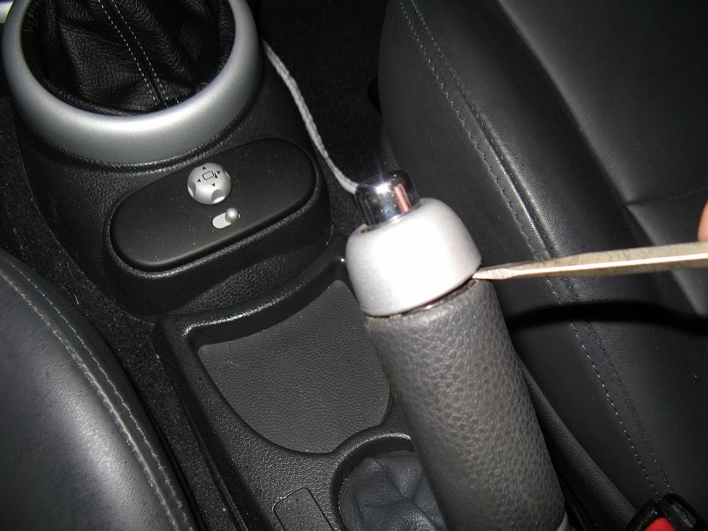
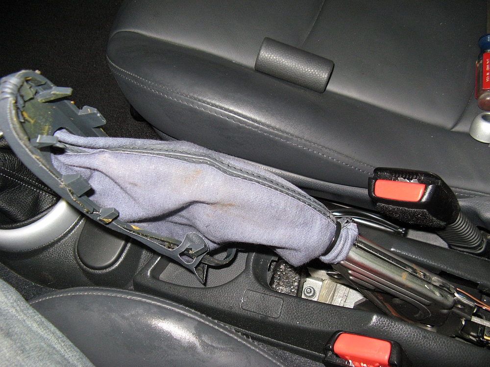
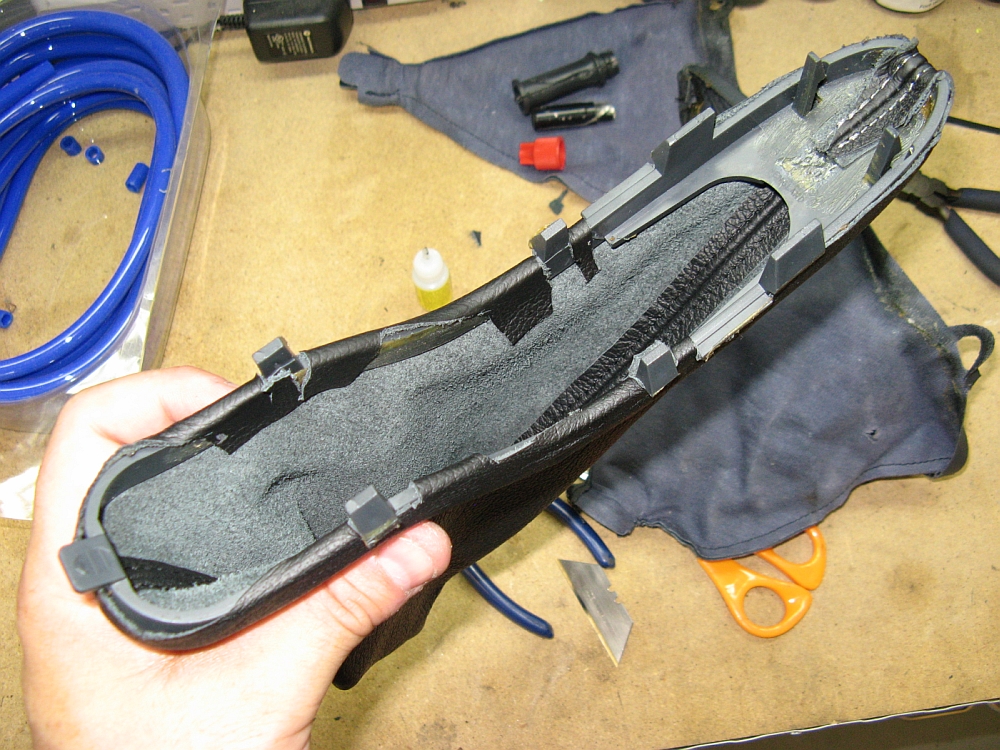
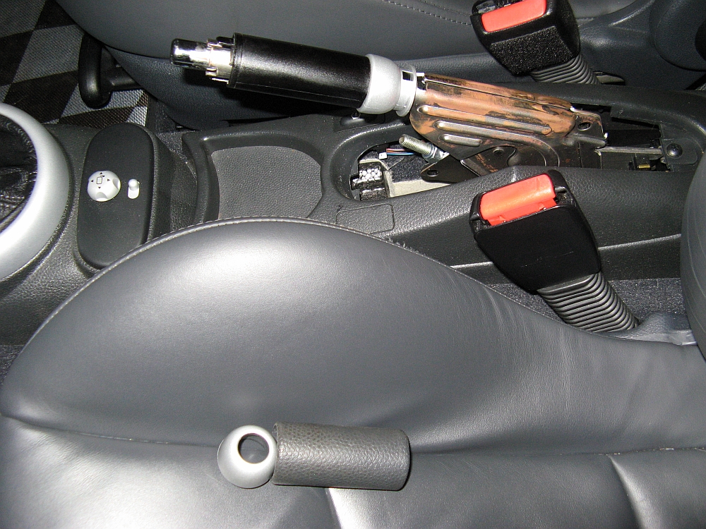
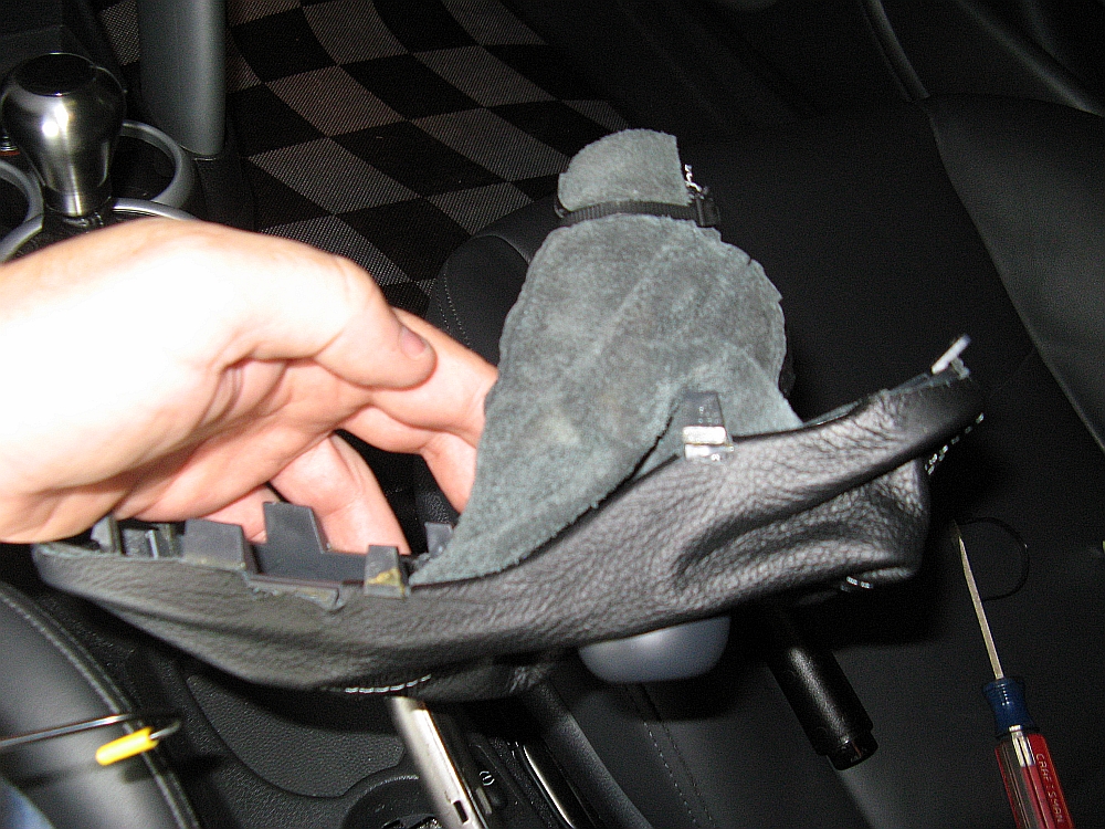
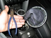
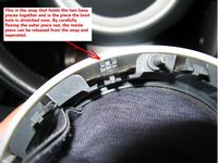
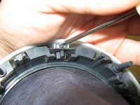
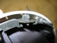
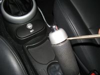
The process with the new parking brake boot installation is similar. The handle will have to be removed- using a small screwdriver to help the trim ring at the front of the handle can be snapped off (careful not to damage the plastic) and the handle can then be pulled off. To remove the boot, pinch the boot at the back and pull up to unsnap at the rear. Working your way to the front, there are retainers on either side that you will need to push down/in and then pull up as they release. These side retainers are easy to break so go slow. The front is then unhooked after cutting the zip tie that holds the boot to the handle and the boot can be removed. As with the shift boot, the new boot will require some cutting to work with the base, I lined up and glued the front and rear and worked around the sides from there trimming and gluing. Once the new boot is attached, it can be turned inside out and reattached using a zip tie and then slipped in at the front and snapped down on the sides and back. The handle is reinstalled and the silver piece that retains the handle snapped on.
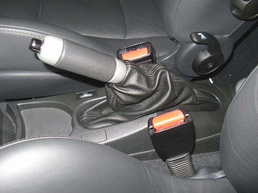
So how does it feel? I know there are a lot of naysayers regarding cut shifters and I would agree on some cars. But for this car, cutting the stick down made the shifter perfect for me, so perfect that I am not sure I will be installing the Helix SS and/or the B&M bushings. The shifts are short enough and feel much more solid. Compared to aftermarket shortshifters out there that replace the shifter (B&M, etc), the cut shifter in my car is about the same height above the pivot point. Reverse is a little harder to get into, but not bad enough that I have any regrets. Cutting the stick coupled with the weighted UUC knob really improved the shifter more than I would have believed prior-YMMV.


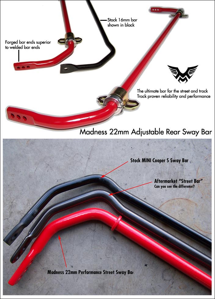
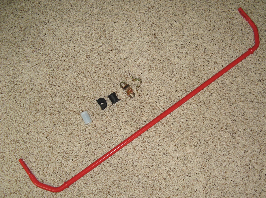
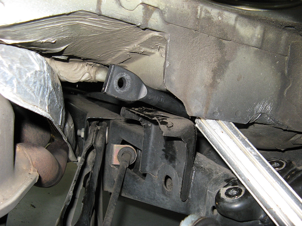
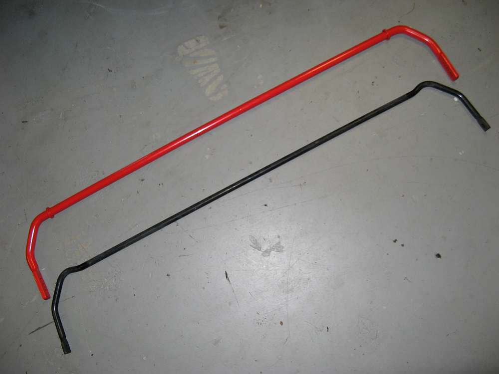
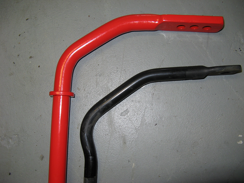
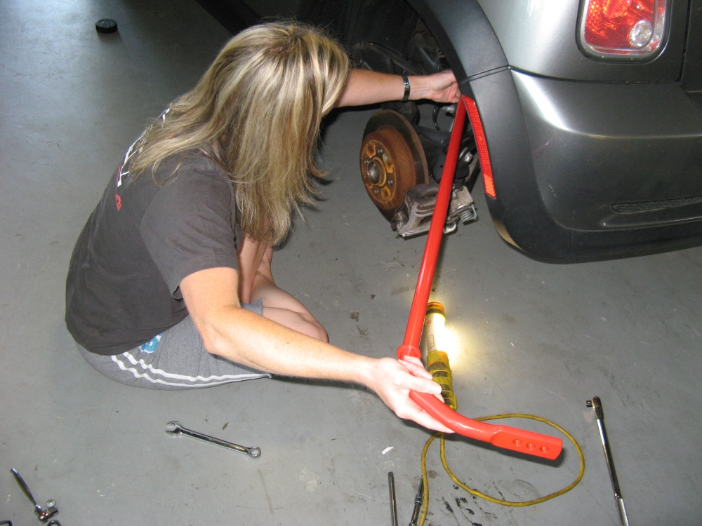
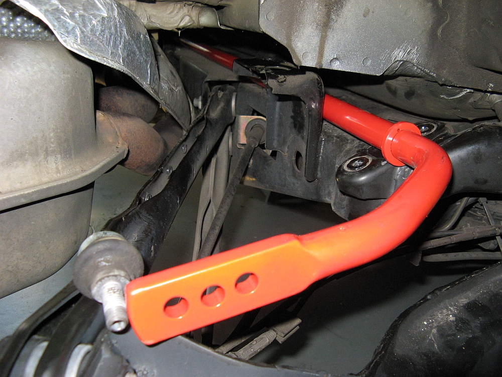
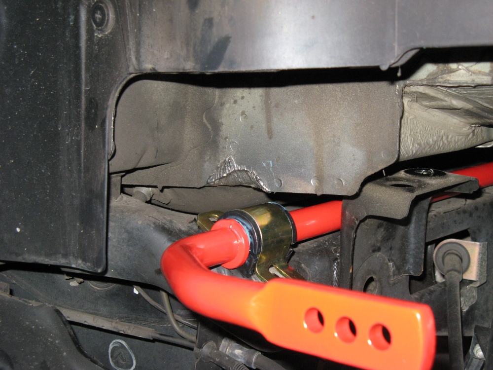
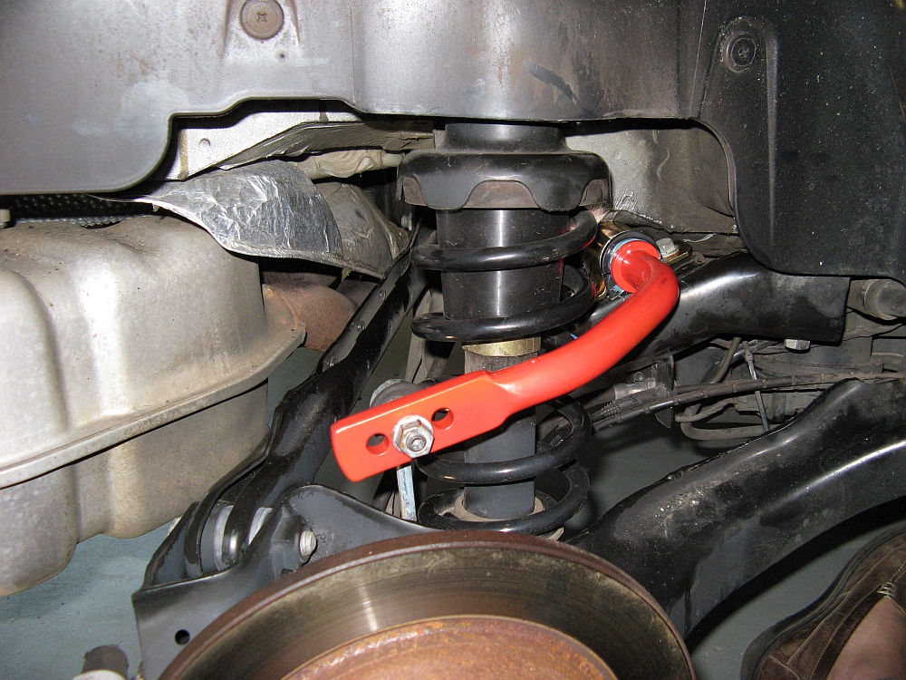
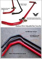
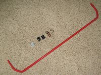
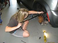
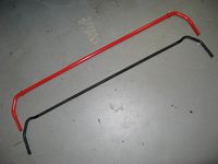
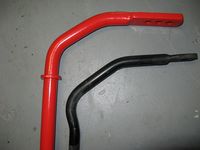
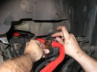
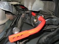
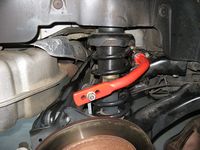
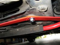
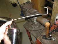
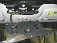
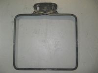
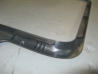
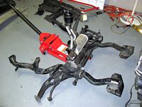
22mm forged solid adjustable rear sway bar from Mini-Madness installed, MM instructions HERE. Since I have used Hotchkis in the past with good results, I looked at the Hotchkis Competition hollow bar but found some issues on other forums where the hollow bars failed (see some examples HERE and HERE). After reading the Whiteline white paper HERE and giving it some more thought, I decided that the added weight was not an issue and that I preferred the stronger forged bar to the hollow bar and went with the MM bar.
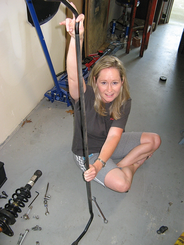
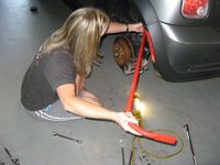
I looked at several different installation guides to get a feel for different ways to approach this, found below in the DIY section. It is not required to have a helper but it does make it a little easier when removing the old bar and inserting the new bar- I was able to convince my wife to put on some dirty clothes and come help me.
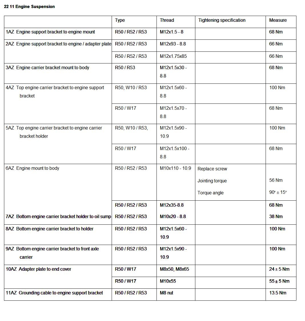
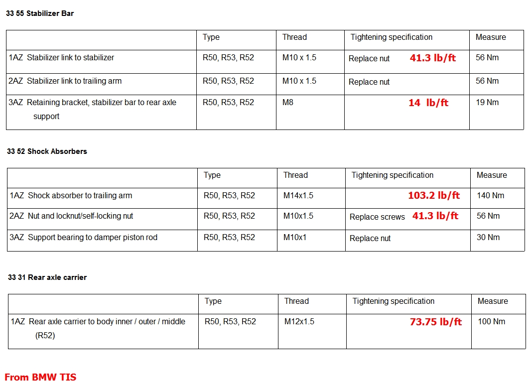
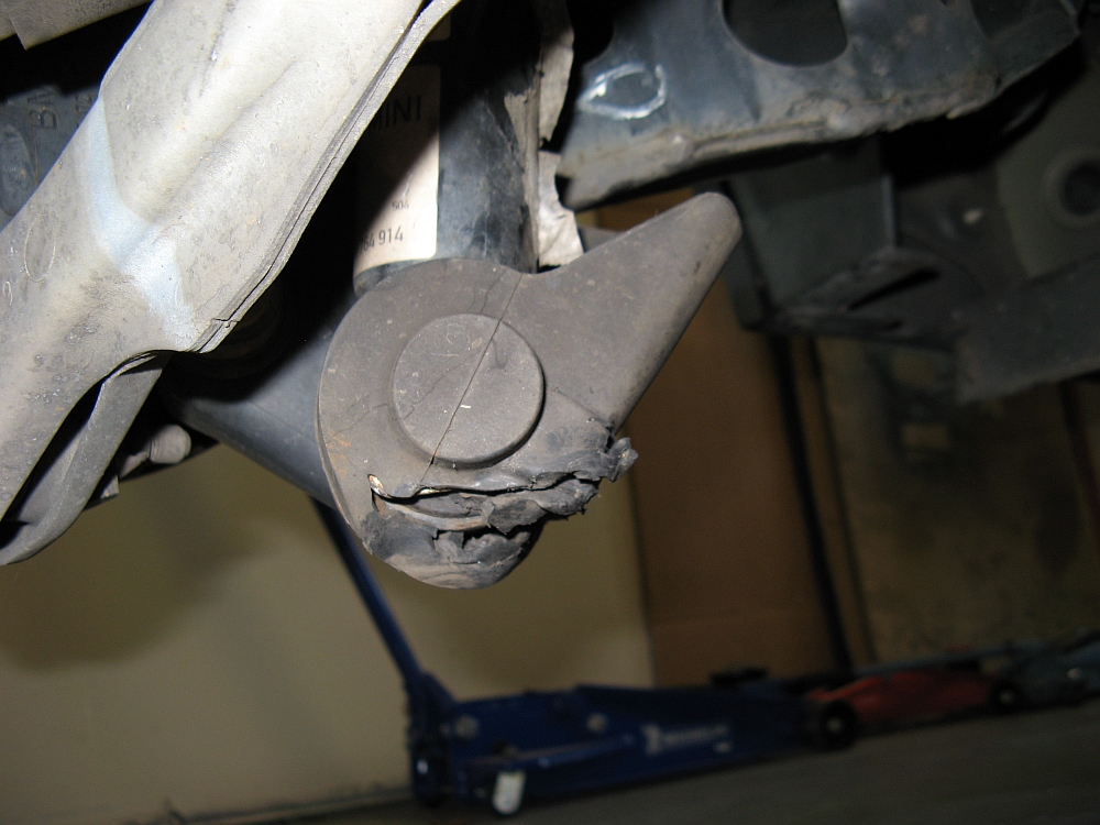
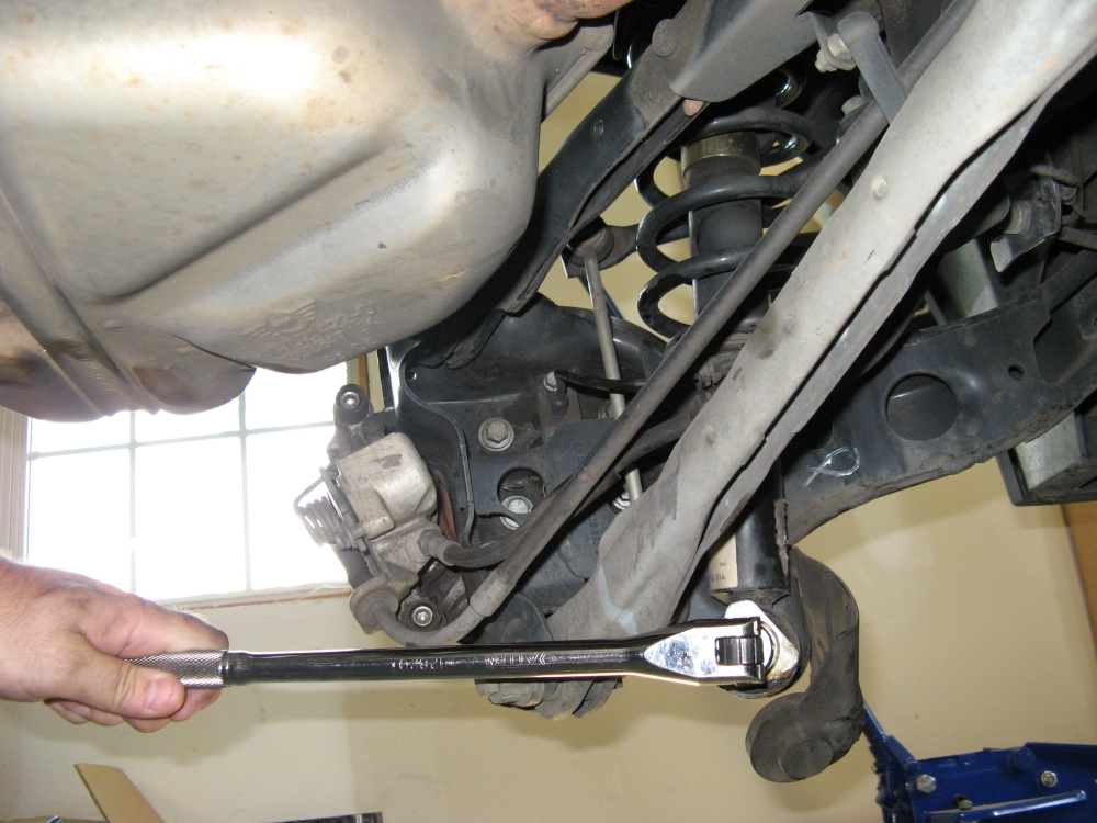
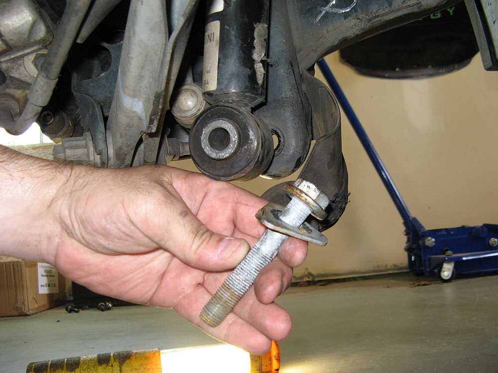
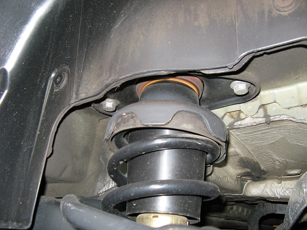
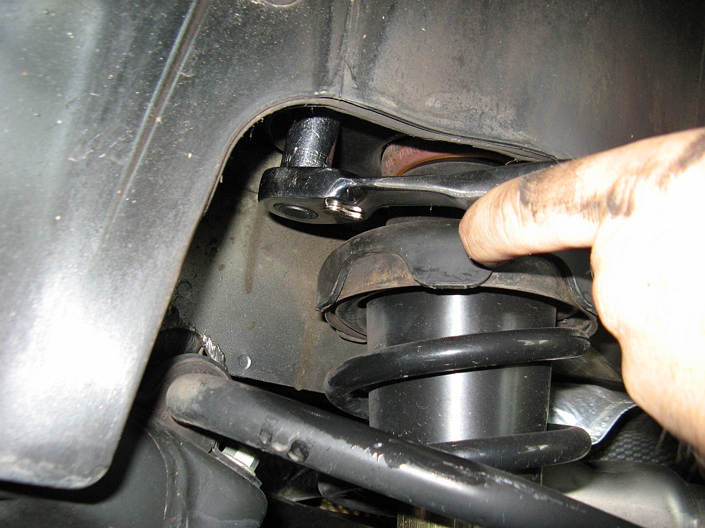
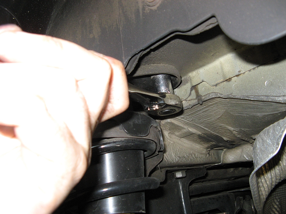
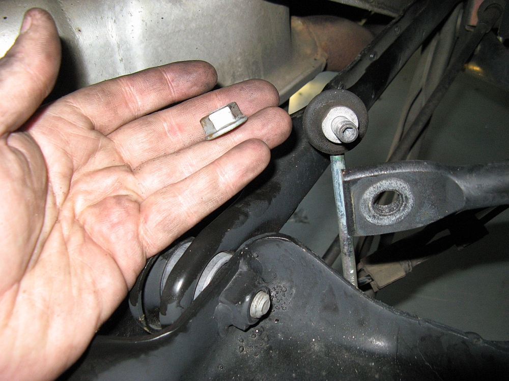
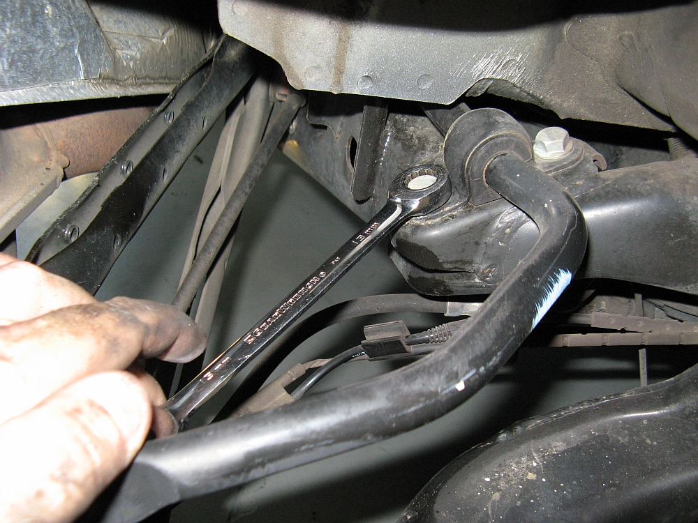
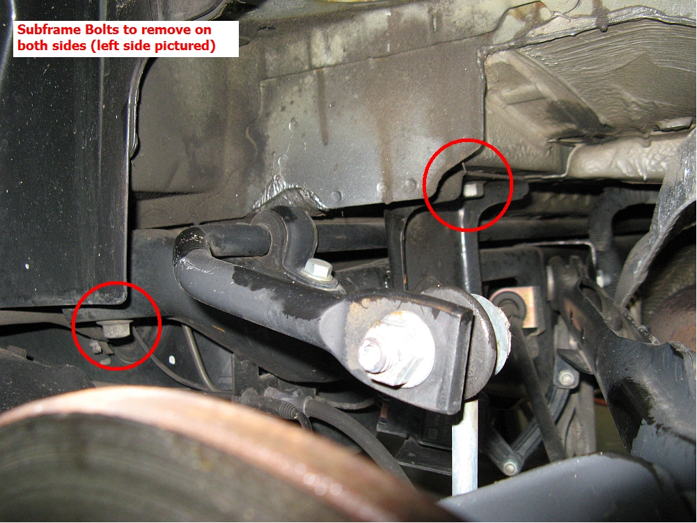
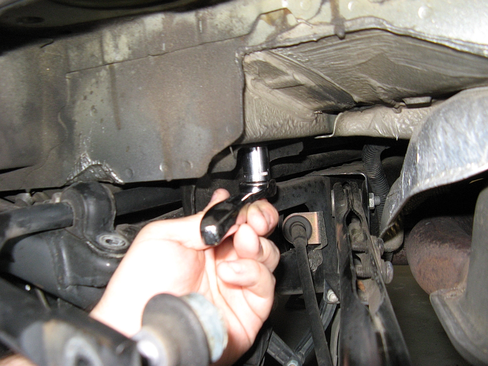
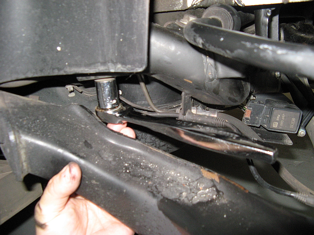
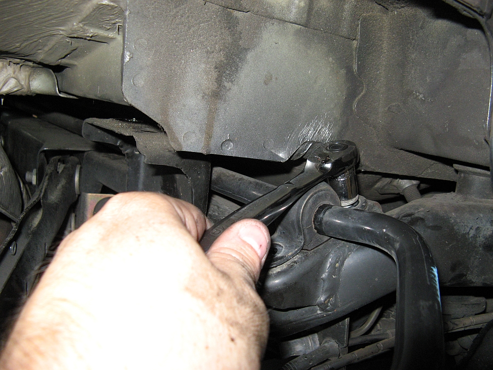
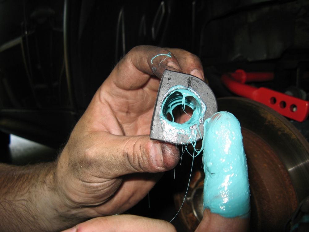
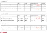
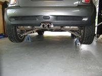
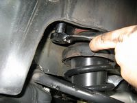
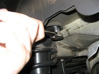
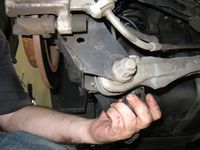
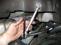
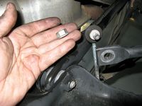
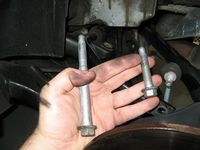
The basic steps are the same, I have included the TIS torque specs with converted lb/ft numbers that you can verify HERE: the car is raised and placed on jack stands, the rear wheels are removed, the brake lines and wiring are removed from the rear shocks, the lower shock bolts are removed, the upper shock bolts are removed, the sway bar endlink bolts are removed, the swaybar bushing bracket bolts are removed, the four subframe bolts are removed, a pry-bar is used to push the subframe down to allow clearance for the sway bar to be pushed from the right side to the left side where the old bar is pulled out (careful around the battery wire in the center for S models), installation is reverse of removal with some grease on the new bushings and paying attention to torque specs.
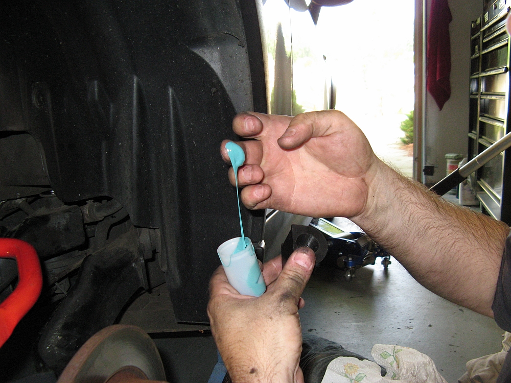
I could not get the front bushing bracket bolts out until dropping the subframe, but that was not a problem. The grease that is supplied with the MM bar is something I have NEVER seen before, it is very elastic and sticky and I'm not sure it will ever go anywhere now that the bar is installed.
The weekend after installing I was able to hit some of the local mountain roads, WOW- what an improvement, this should be one of the first mods anyone does.


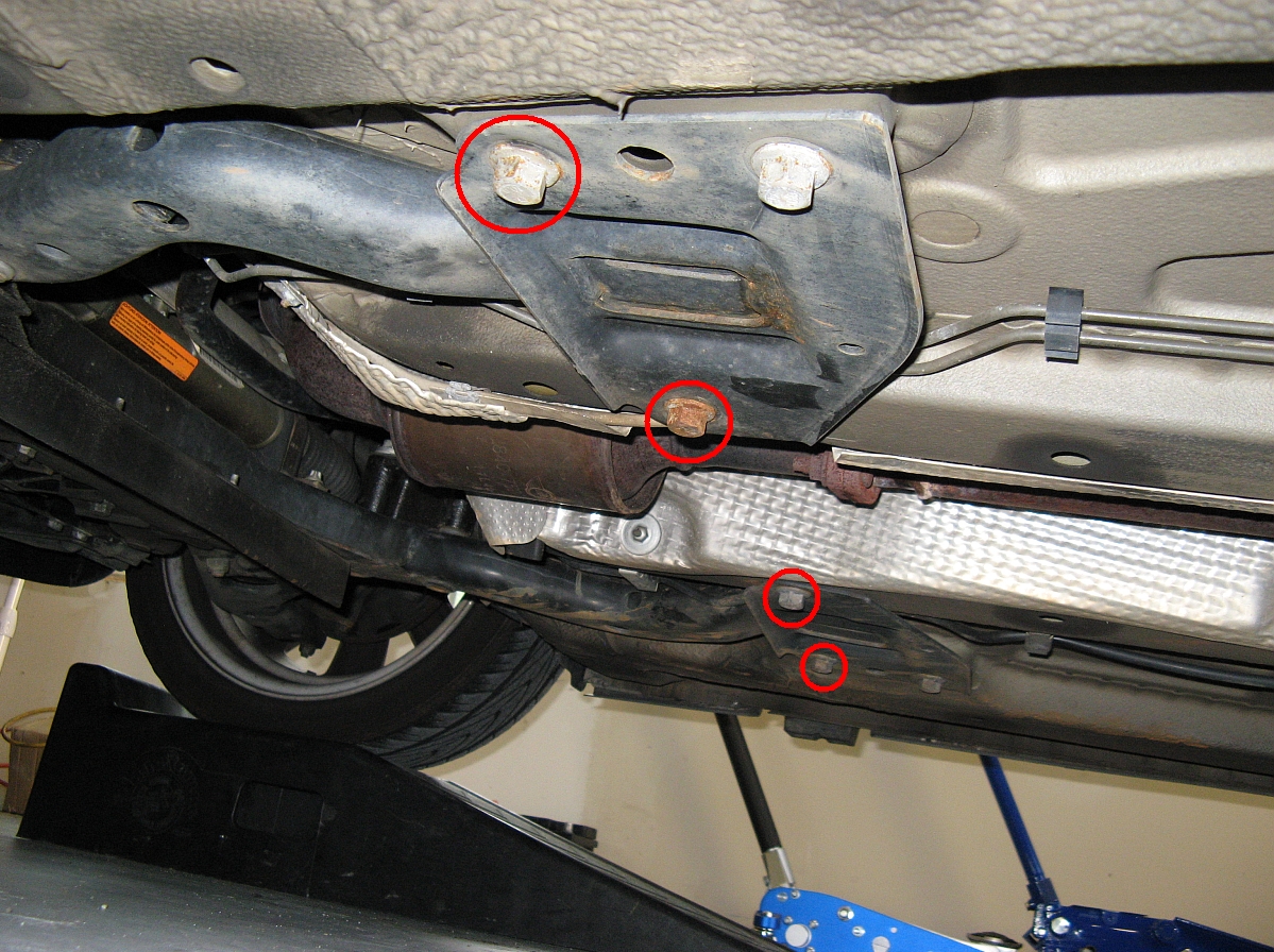
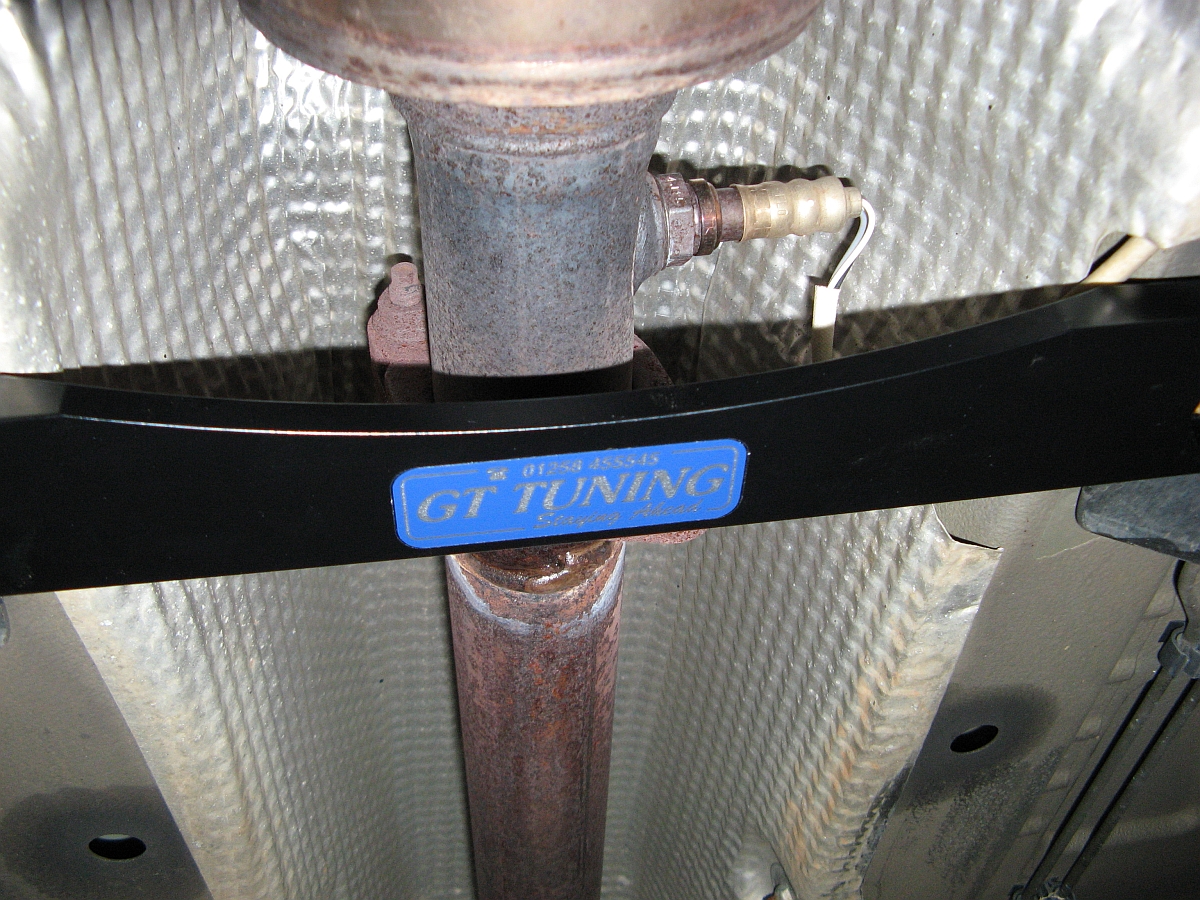
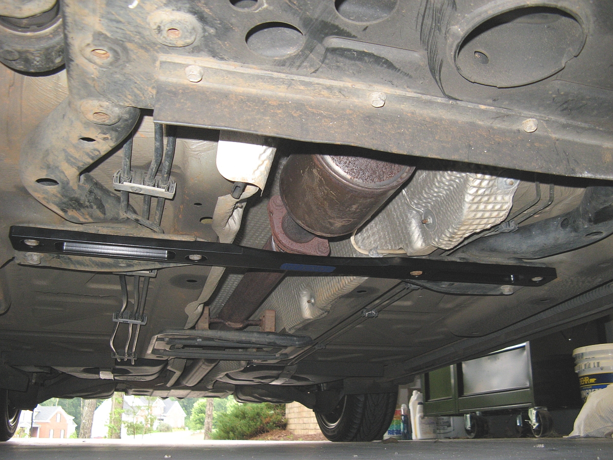
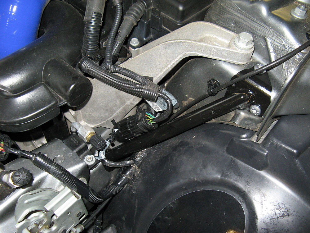
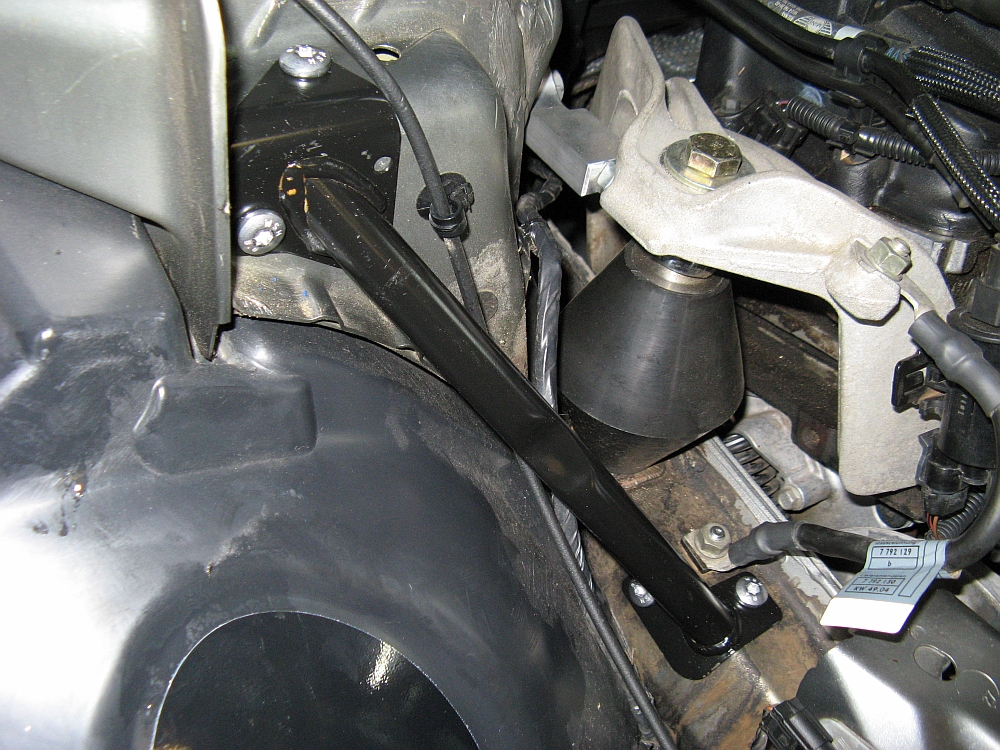
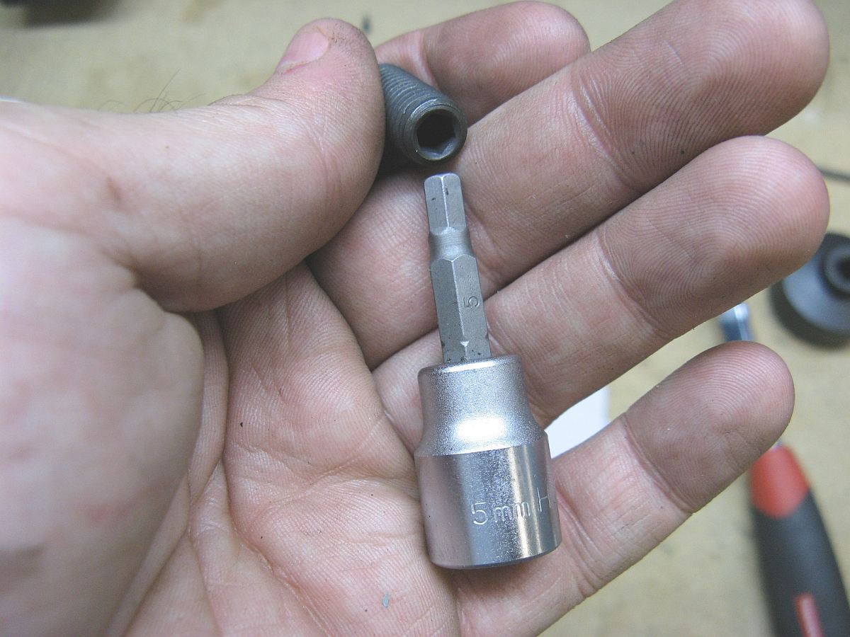
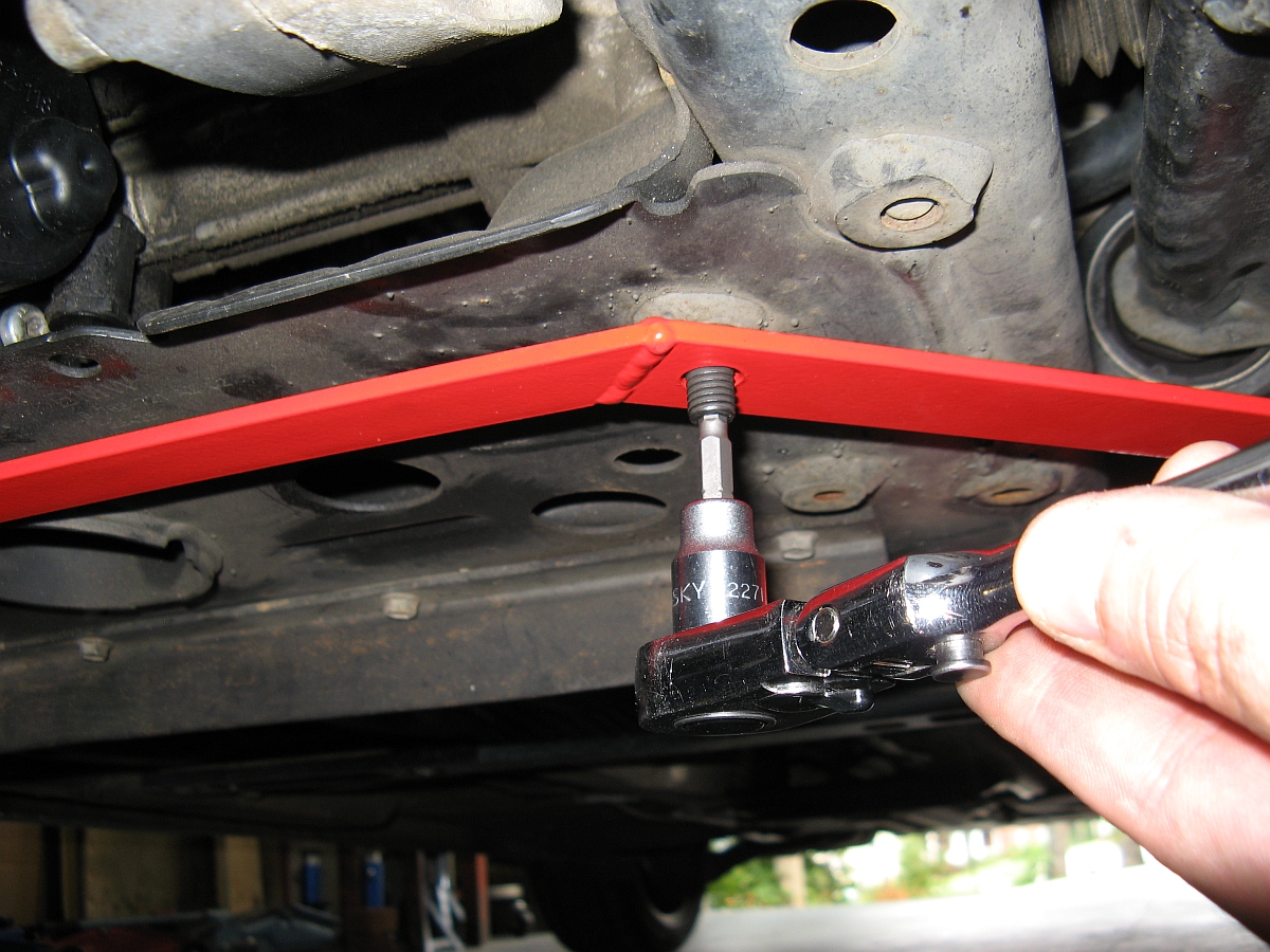
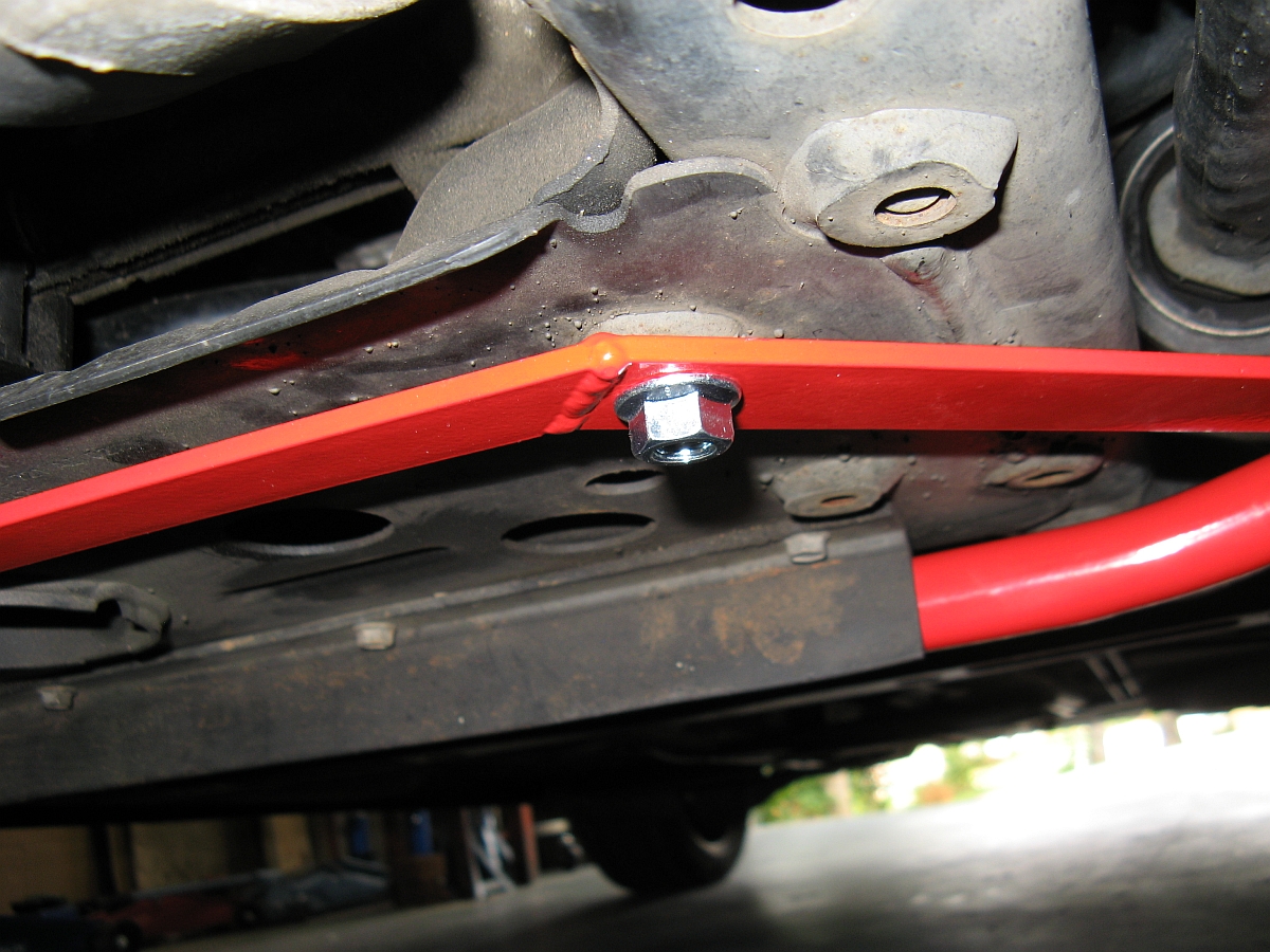
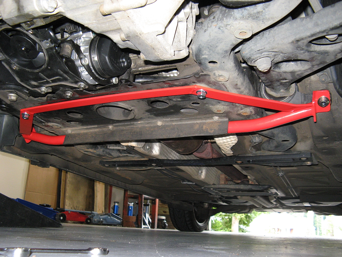
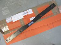
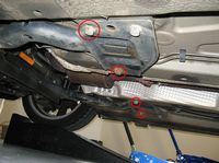
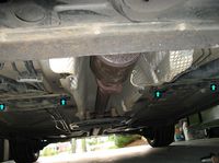
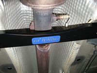
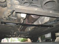
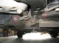
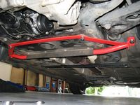
Lower mid brace from GT Tuning installed. Easy 10 minute installation: Drive car up ramps, remove 4 bolts with 16mm ratchet, install bar and reinstall bolts, torque to 74 ft/lbs- DONE. The brace strengthens the weak area where the front subframe bolts on either side of the exhaust tunnel, I can feel the car wanders/tramlines less and overall feels more solid.... to be honest, a lot more than I expected from this brace. I expect that when the MM subframe brace arrives it will improve even more.
The Mini2 intro thread for this brace can be found HERE and the thread on NAM that convinced me to try this brace and the MM brace paired can be found HERE.


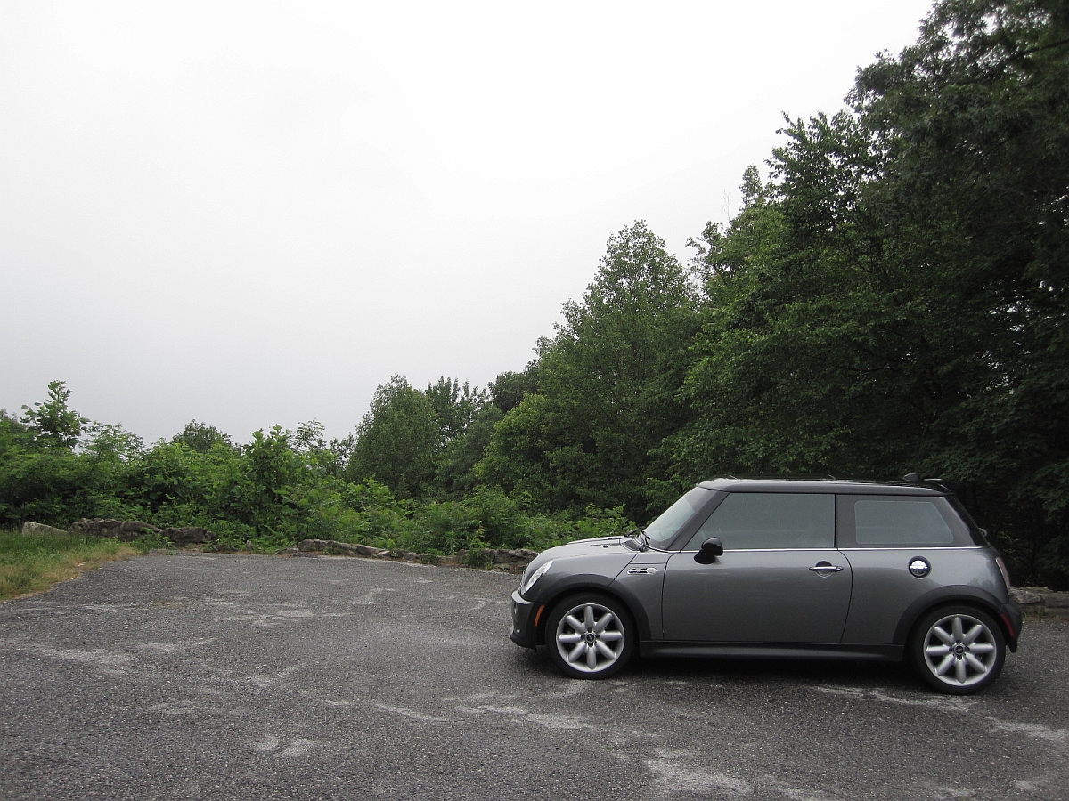
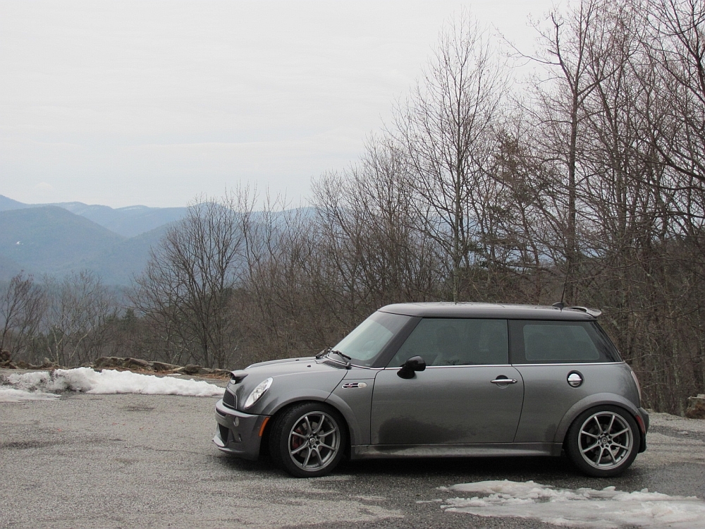
Day trip to North GA Mountains for some driving - weather did not cooperate though. Some rain and fog restricted how enthusiastic driving could be but, WOW, the MCS is great with just a rear sway bar upgrade. Stopped off at Chestatee Overlook (off HWY 60 on the way to HWY 180, aka Wolf Pen Gap/Little TOD) for some pics, normally you can see mountains in the background. Power steering pump was not cooperating either, it decided to be in off mode for 90% of this trip- will be replaced soon:


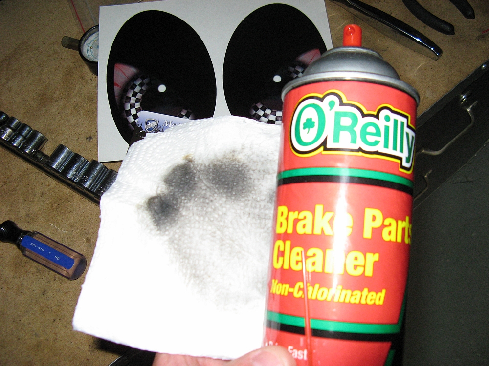
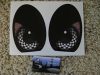
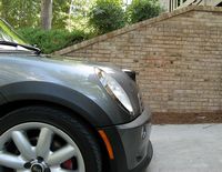
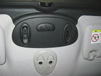
Rogue Mini Eyes from Motoring Alliance installed (archived store page HERE). I cleaned the plastic with brake cleaner to remove all oil/grease/wax prior to application. I had just returned from a 10-day business trip so please excuse the DIRTY Mini

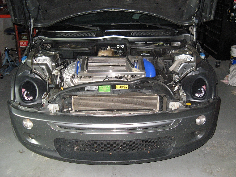
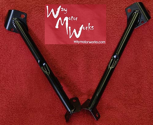
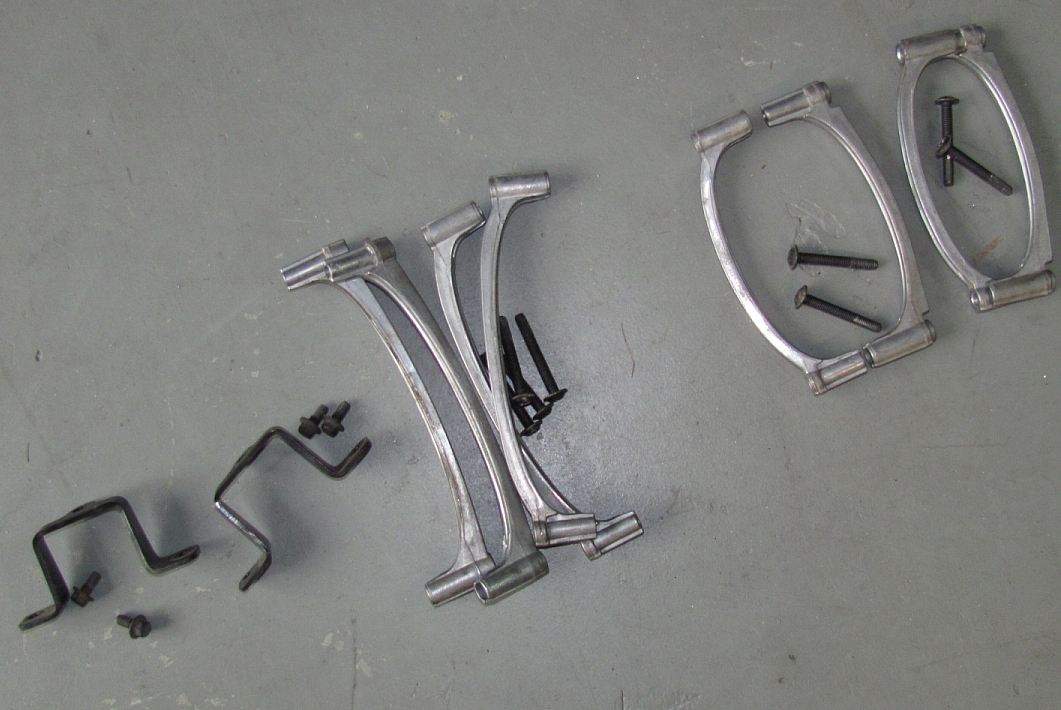
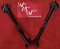
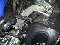
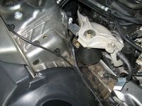
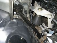
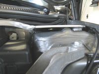
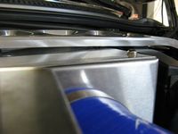
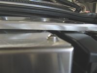
Cabrio braces from Way Motor Works installed. These are OE braces that come installed on the Cabrio to stiffen the chassis up, can't hurt to have them on a hard top car and at the price it is hard NOT to install them. Ways package comes complete with the T30 Torx head bolts to install the braces using factory supplied bolt holes. The part numbers for the braces are 51617123515 (left) and 51617123515 (right), the bolts are 07146957269 (8 required). Cabrio Brace thread on NAM is HERE.
My installation DIY can be found HERE.

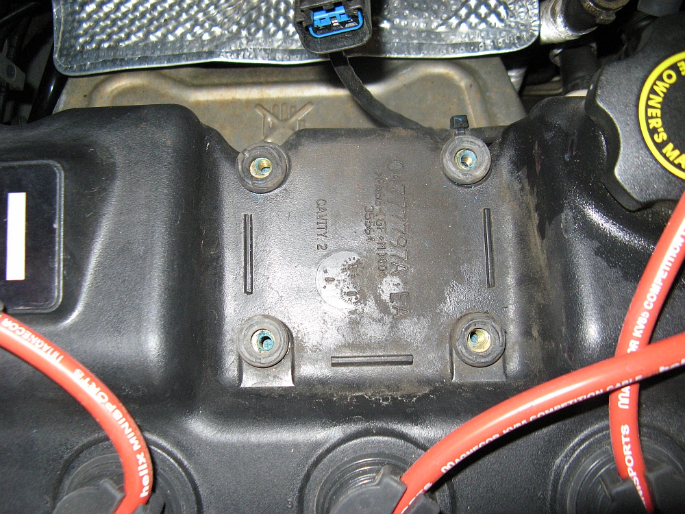
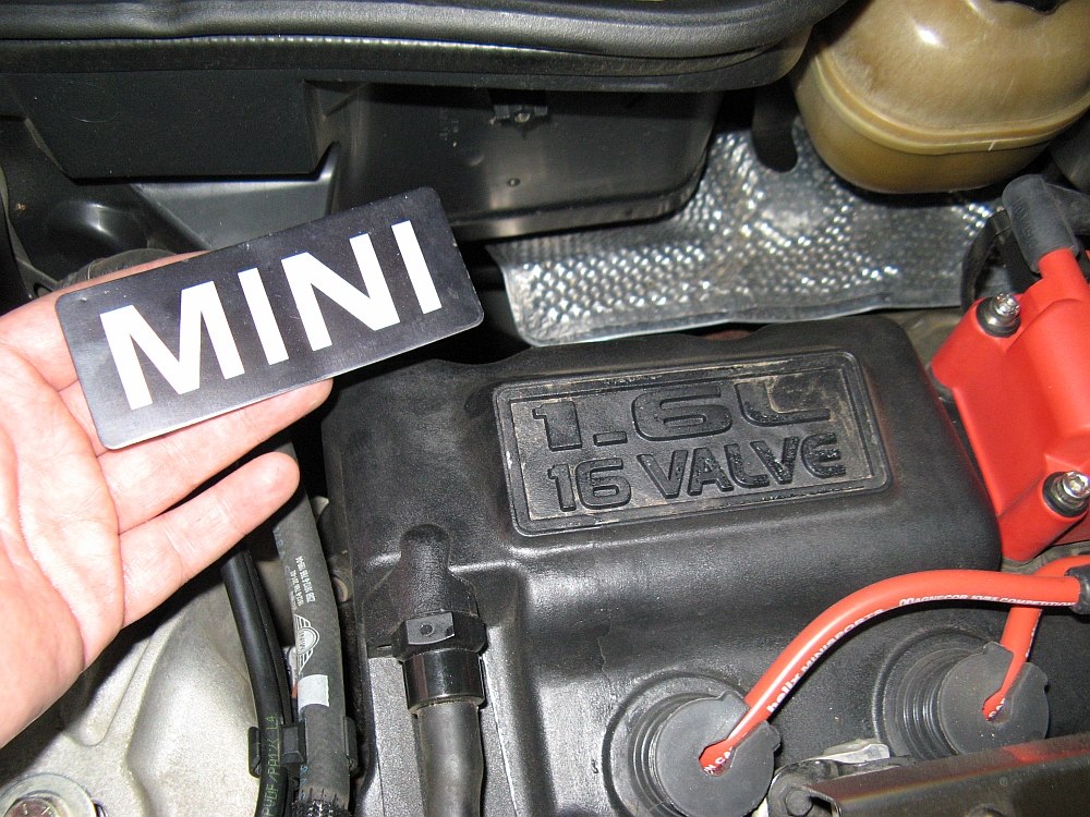
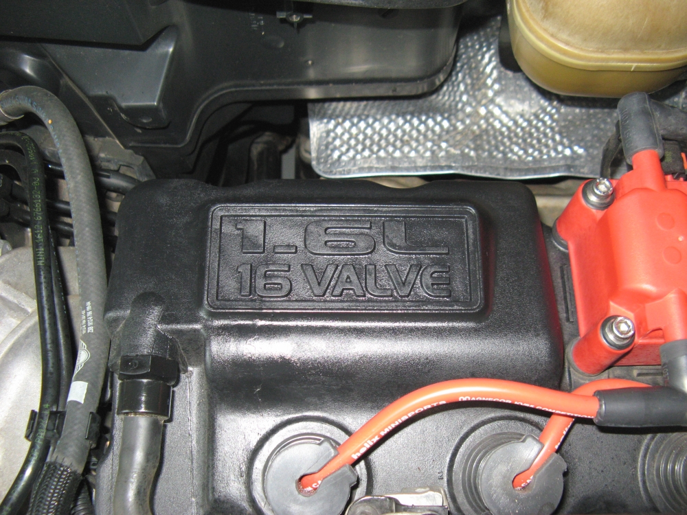
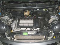
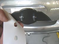
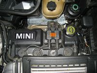
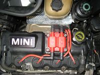
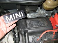
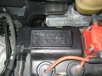
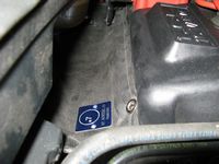
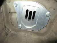
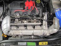
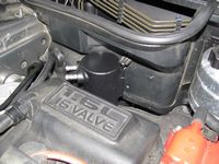
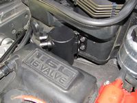
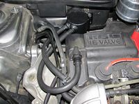
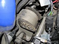
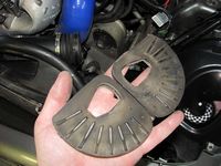
No cost mod- Removing the MINI engine plate to uncover the 1.6L 16V molded into the valve cover.
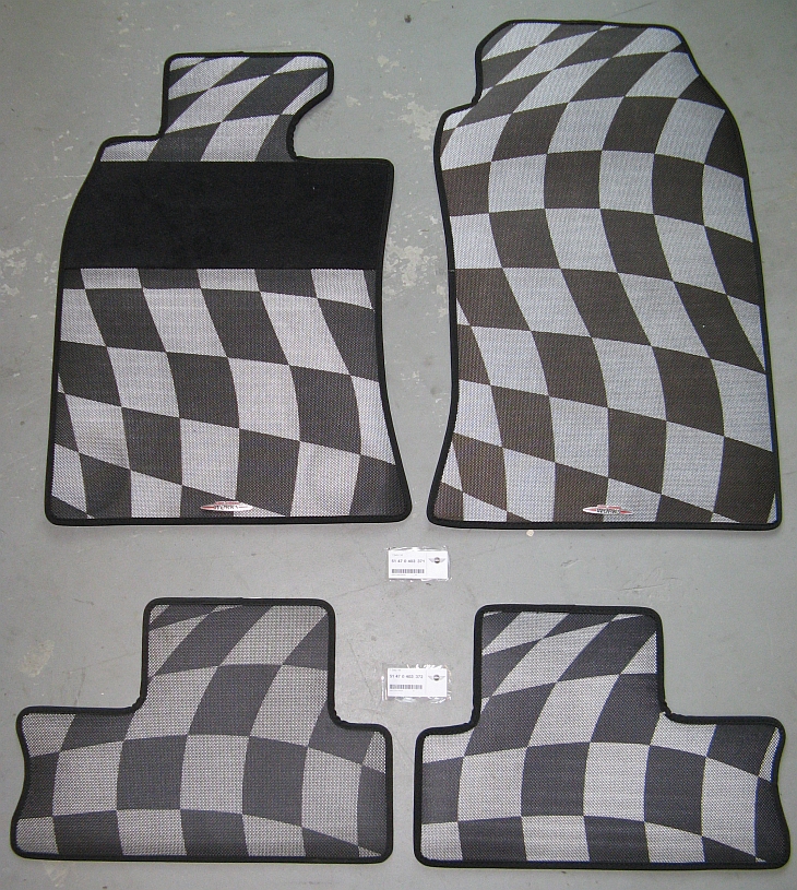
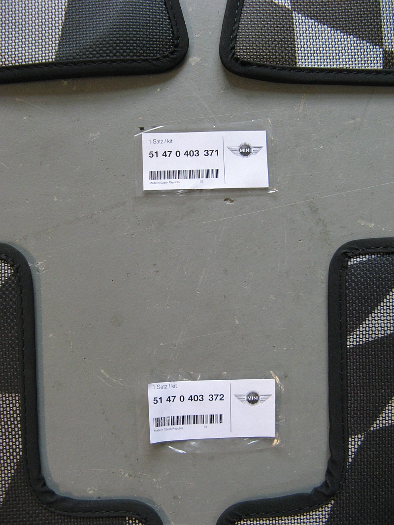
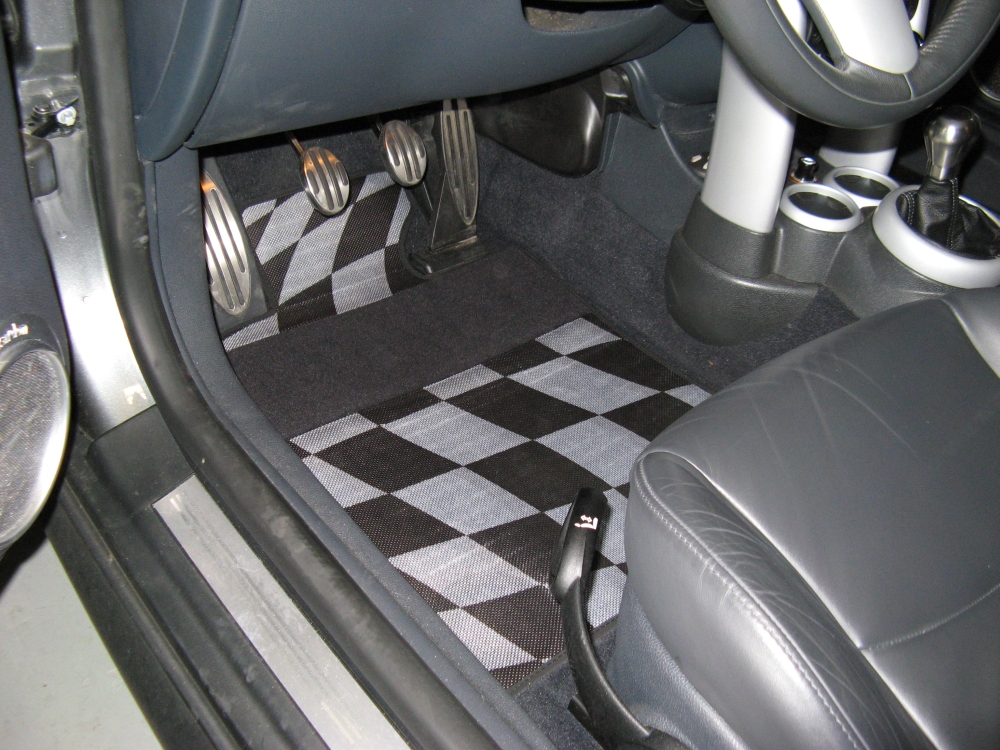
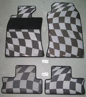
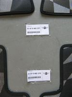
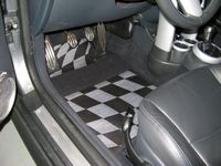
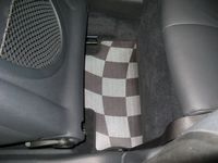
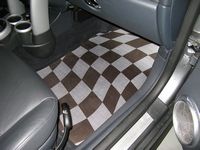
JCW Floor Mats from Classic Mini installed. Jayson is the NAM contact at Classic for discounted parts, phone 440-585-9950 or email bmwparts@driveclassic.com - ask for the North American Motoring forum discount (~20%).
These floor mats are heavier duty rubber with a checkerboard pattern molded in, they should provide the lasting power/protection of the rubber mats but with a little more style:
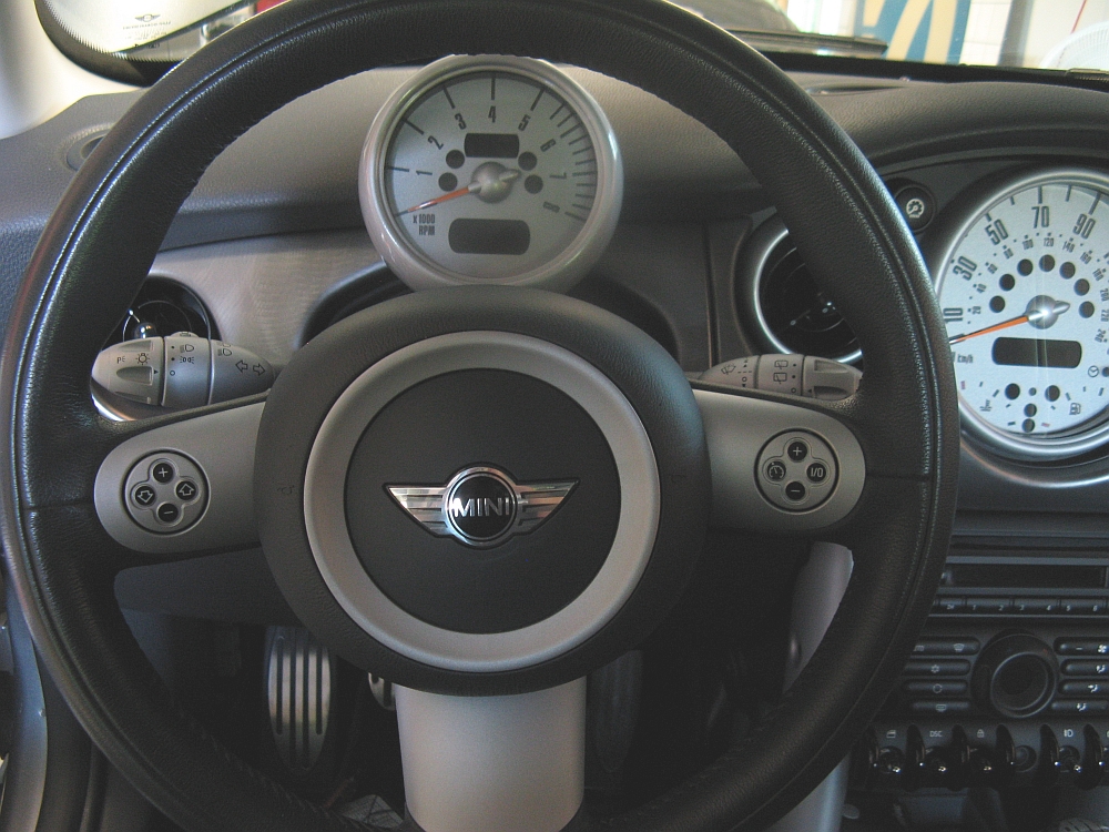
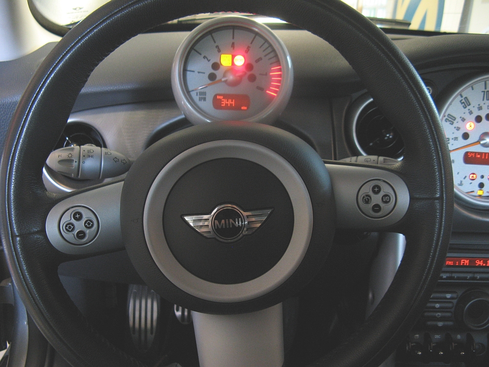
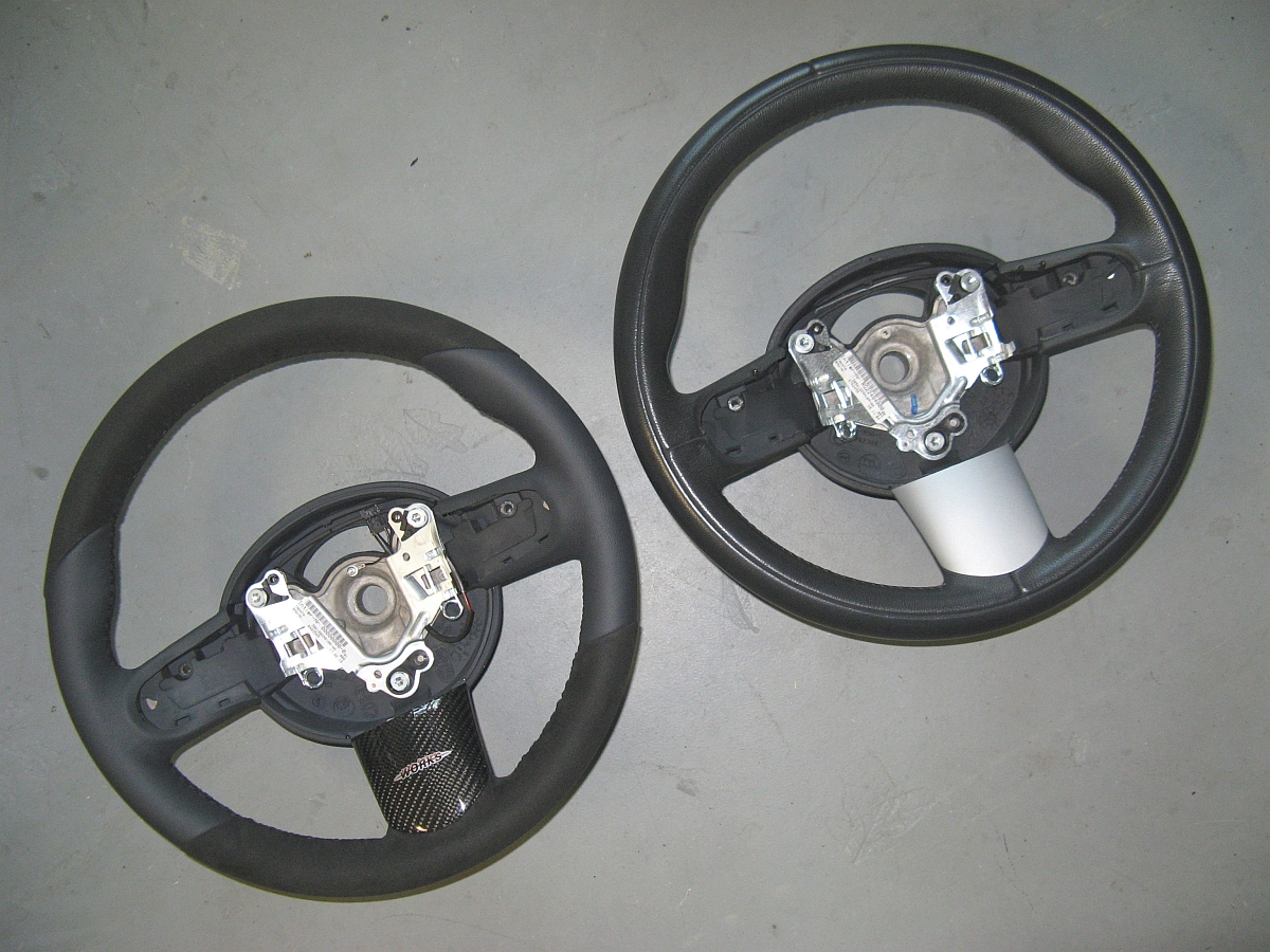
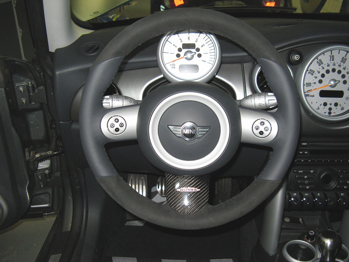
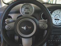
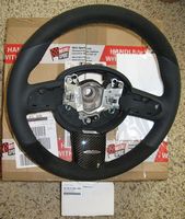
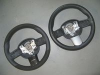
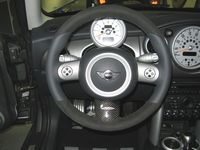
JCW Sports Steering Wheel purchased from UK vendor Mini Genuine Parts. I initially contacted Jayson at Classic Mini but he confirmed the US supply of JCW steering wheels was dried up. The exchange rate is not bad right now so it ended up being about the same price. I bought the leather and Alcantara version (P/N 32300403545) and was limited to the bottom center CF trim piece (P/N 32300403582) since I have the multi-function switches. The wheel is about the same diameter as the Sports package wheel I had, maybe a little thicker, and much better feeling materials covering the wheel. Swap takes about 30 minutes taking your time,
My DIY guide can be found HERE, Motoring File review is HERE.
Since I did this job Thomas Wilding has posted a video on how to troubleshoot and rebuild the pump HERE.
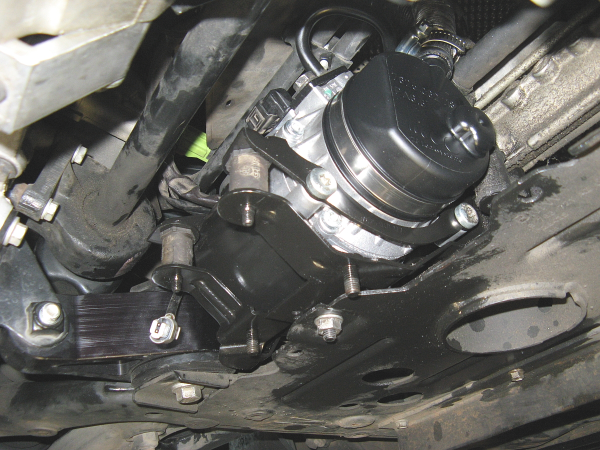
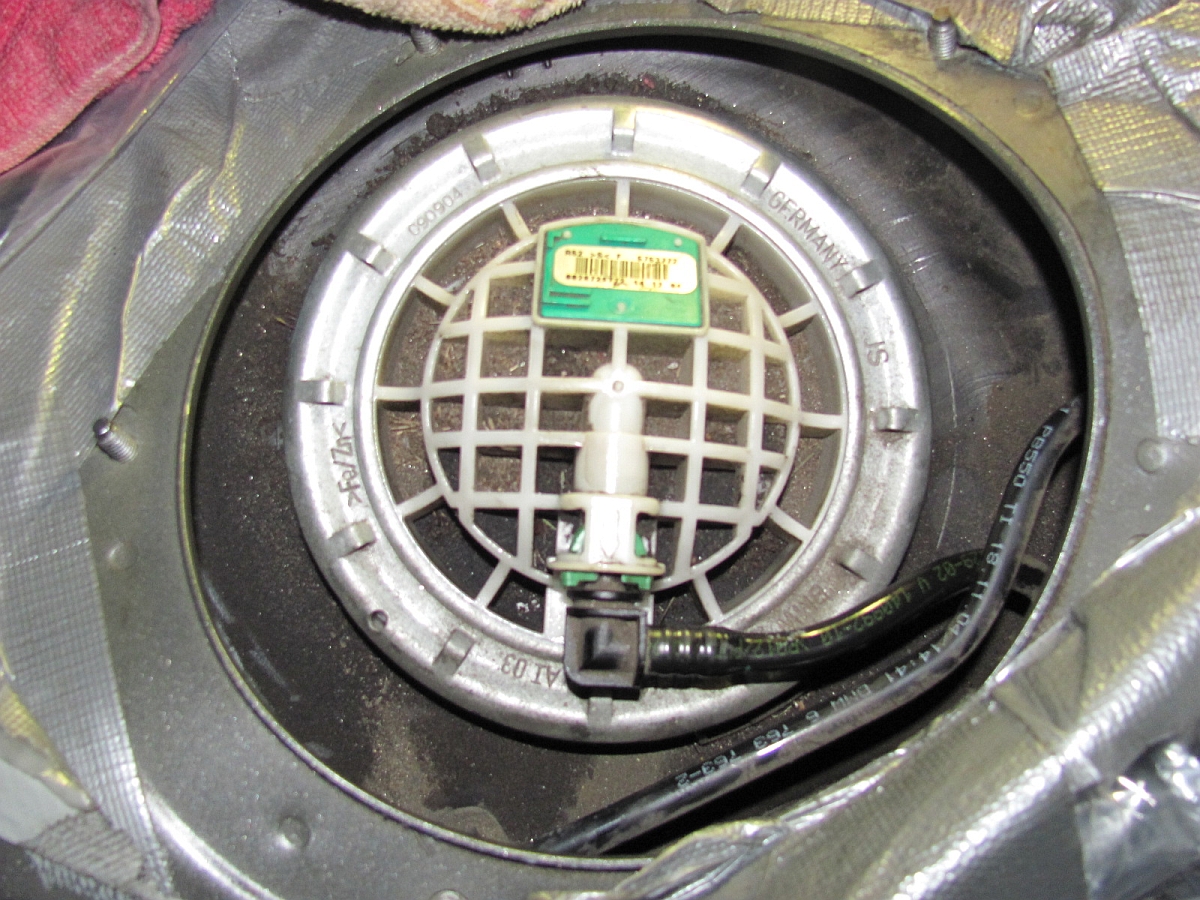
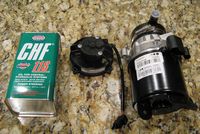
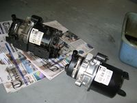
The power steering stopped working for a day or two so I assumed the electric pump had finally gone to power steering heaven after 110k miles (but it ended up lasting intermittingly for about another 6k miles until I finally replaced it). I found a NEW (not remanufactured that some sell as new) ZF power steering pump at Steering Components Plus (doing eBay business as seller jorgenauto) for $474 shipped with no core charge/requirement (example eBay listing HERE).
This would leave me with one out of the car to send in for a rebuild, BBA-Reman (also eBay store HERE) offers a lifetime warranty and the rebuild of mechanical/electrical parts for $200 (example eBay listing HERE).
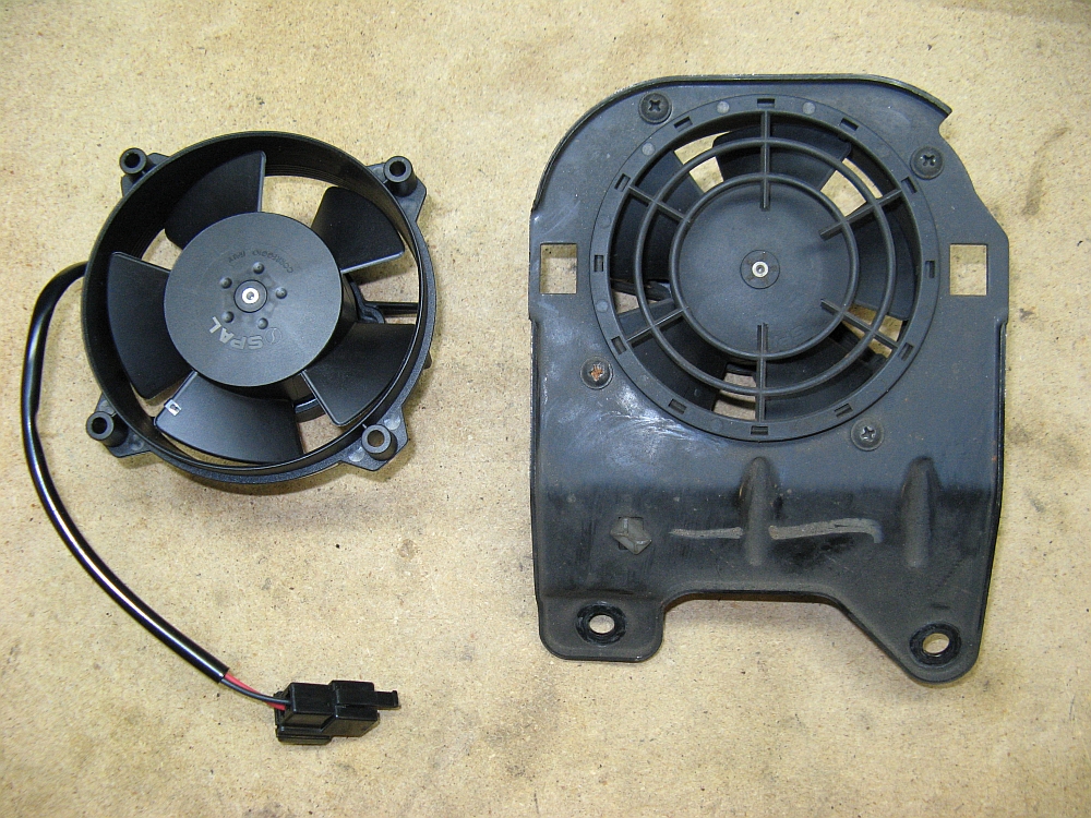
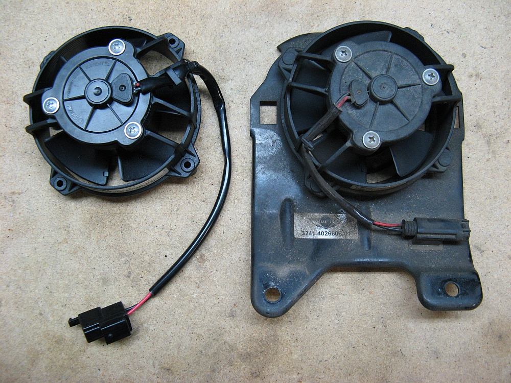
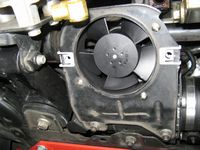
I also ordered a SPAL replacement fan, my fan was still working but I felt if I was installing a new pump, I would go ahead and replace the fan as well. The SPAL P/N VA32-A101-62A was only $60 from A1 Electric, their P/N is 30103018. This fan is a direct replacement for the Mini fan except the power wiring harness has to be spliced into the Mini plug that you will remove from your dead fan. The SPAL fan is made in Italy and reputed to be better than the "other" manufacturer(s) fans that were used, and ordering this way is a LOT cheaper- I don't mind splicing in a harness connector.
THANKS to MikeL at NAM for finding this
Also critical is the choice of power steering fluid, our electric power steering pump takes ONLY Pentosin CHF 11S, the cheapest I found it locally was at NAPA for $22 out the door, it takes a little less than a can if changing out the pump.
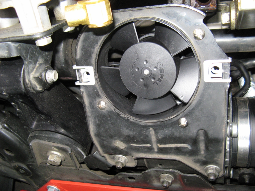
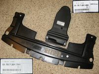
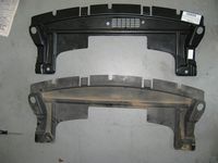
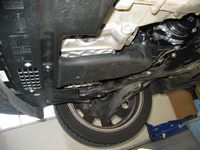
I also sourced the OE fan duct and panel from Moss Mini, they had it conveniently packaged in kit form. This duct provides air to the fan but offers a little more protection to keep road debris from getting into and stopping the fan.
My DIY guide for the power steering pump replacement, fan replacement, and OE fan duct can be HERE.


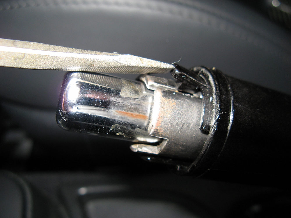
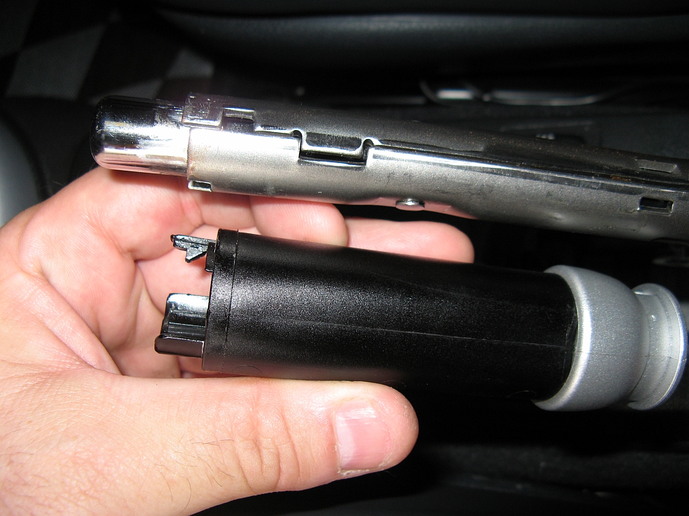
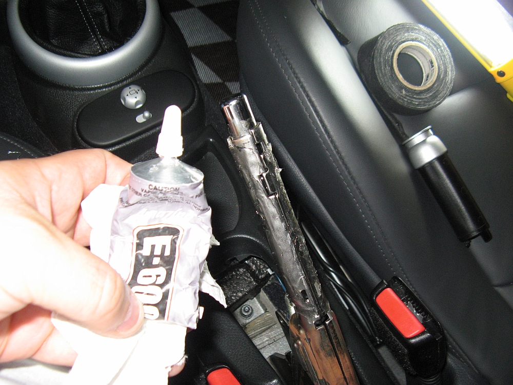
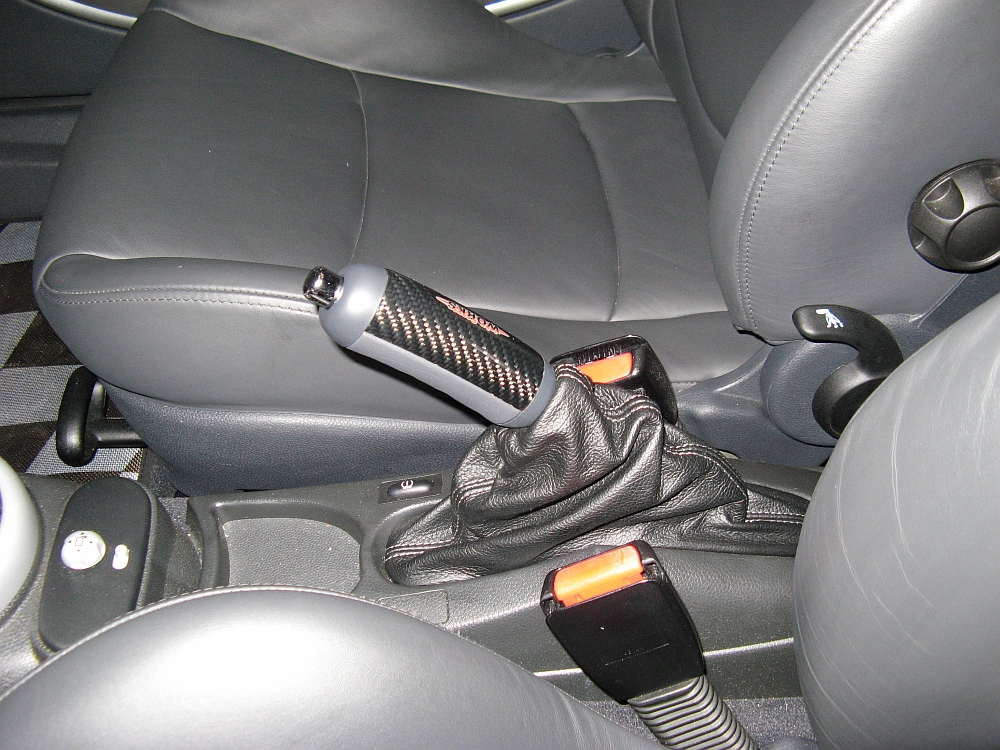
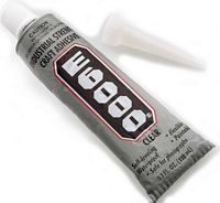
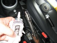
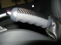
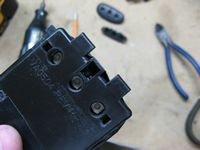
After installing the JCW steering wheel, the plastic and rubber parking brake handle looked cheaper than it did originally.....and it looked pretty cheap then. I purchased a JCW brake handle from the UK, the only difference being the UK part has the JCW logo facing the passenger seat (driver in UK)- no big deal for me since it was $50 cheaper than the US one. I figured the JCW brake handle would attach like the OE one.....but it does not. The OE handle is released by lifting a locking pin and sliding off (disassembly up to this point detailed earlier in mod life HERE). The JCW part, as explained in the Mini supplied instructions HERE show that it has to be glued on. Oh well, some of the forum guys have had success wrapping the metal handle with tape and then force fitting the handle. I started down that path originally but after a few attempts decided I didn't want to go that route. I decided to glue it on semi-permanently using E6000 adhesive. This would make it solid and if I ever wanted to remove it I could just twist it off (albeit with some force) and peel off the E6000- very similar to silicone but a little stronger bond with less elasticity. The leather bottom has finger indentations and feels/looks so much better.

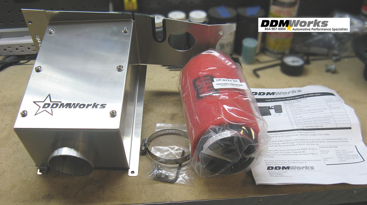
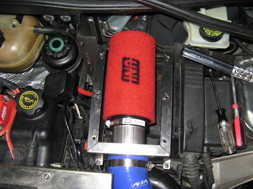
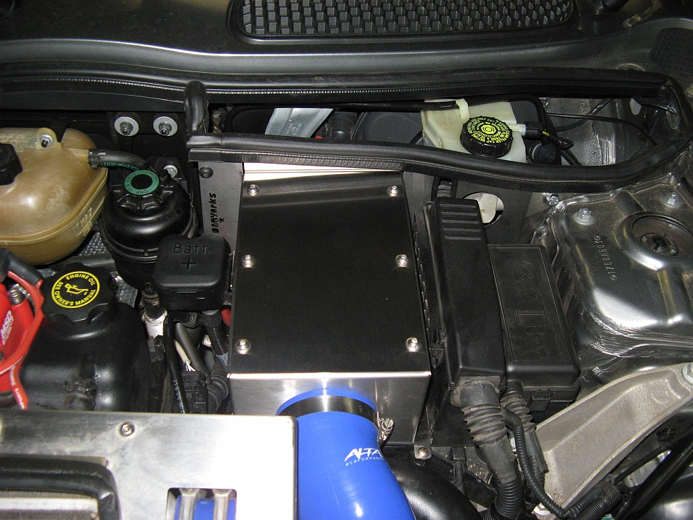
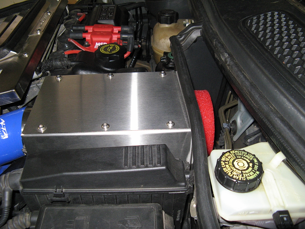
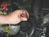
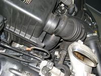
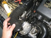
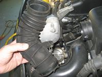
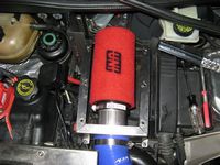
DDM Works R53 Cold Air Intake from EuroSport Design installed. This intake encloses the reusable UNI filter and is integrated with a new rear piece that replaces the OE piece- no cutting so return to stock is easy. The intake seems to offer a bit better acceleration and a lot more supercharger noise
.
My installation write-up can be found HERE
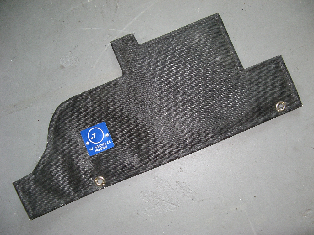
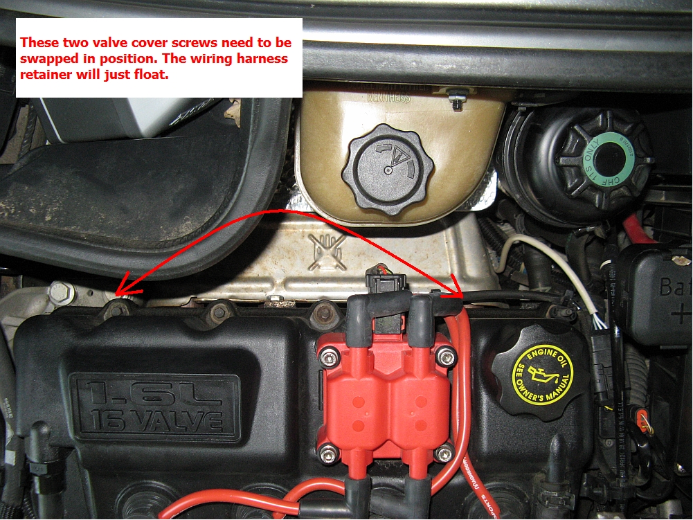
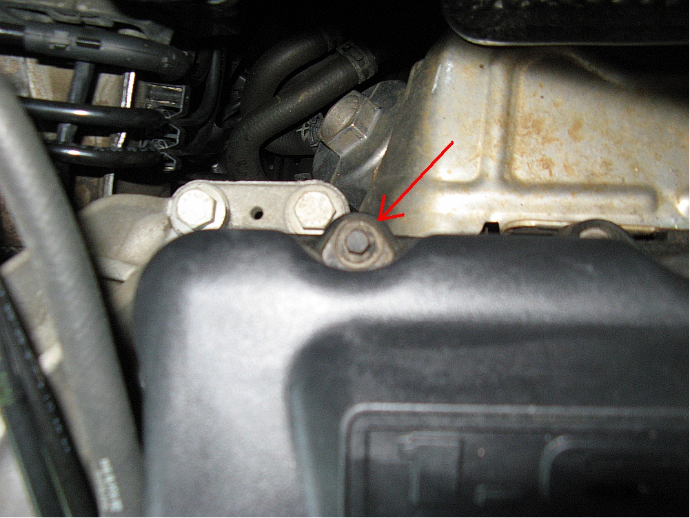
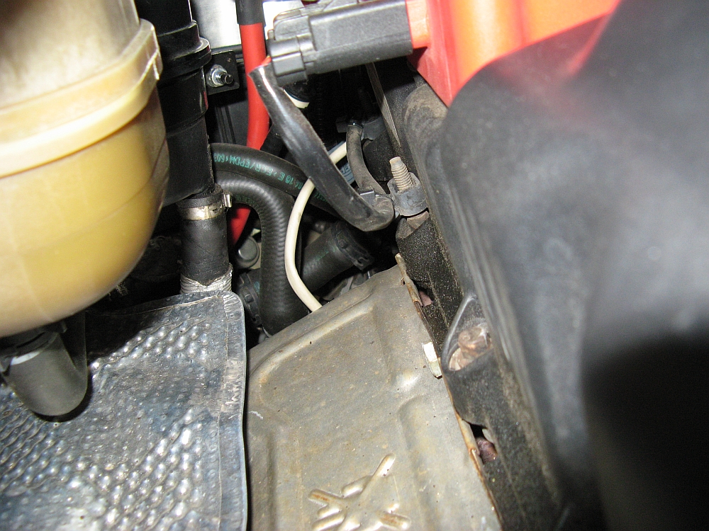
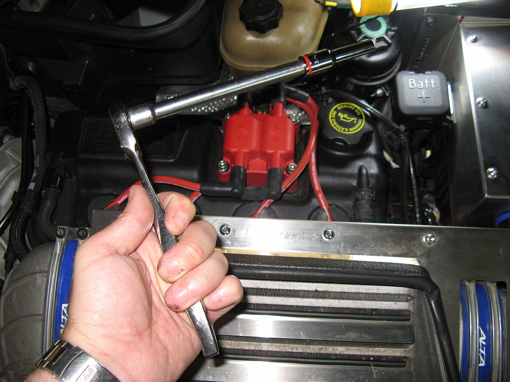
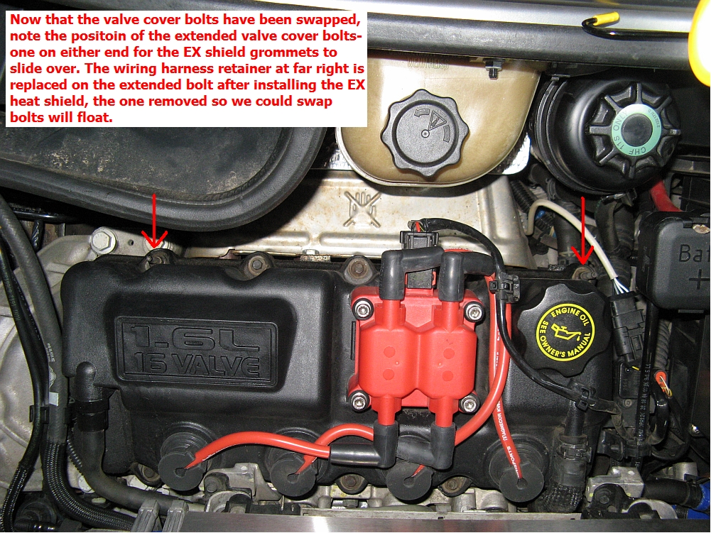
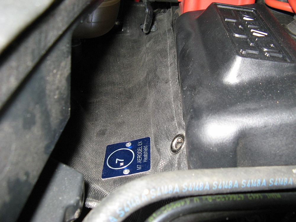
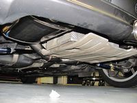
M7 Aerogel EX Heat Shield installed to reduce heatsoak from exhaust manifold (and future header). Easy to install, I just removed one of the bolts/wire harness holders from the valve cover using a ratchet/extension/8mm deep socket and swapped it with a regular bolt on the other end of the valve cover. This allows the grommets on either end of the heat shield to have an anchor point. This heat shield is like a flexible mat and was tucked in over the existing heat shield and around the perimeter. M7 installation instructions are HERE. Product Release information with infrared comparison pics is HERE.


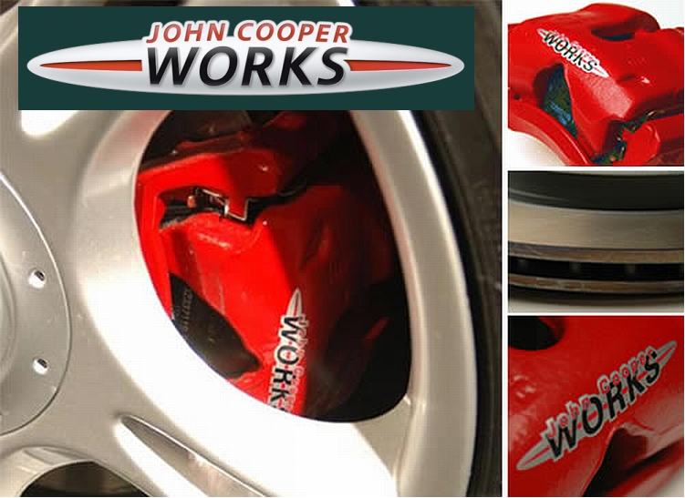
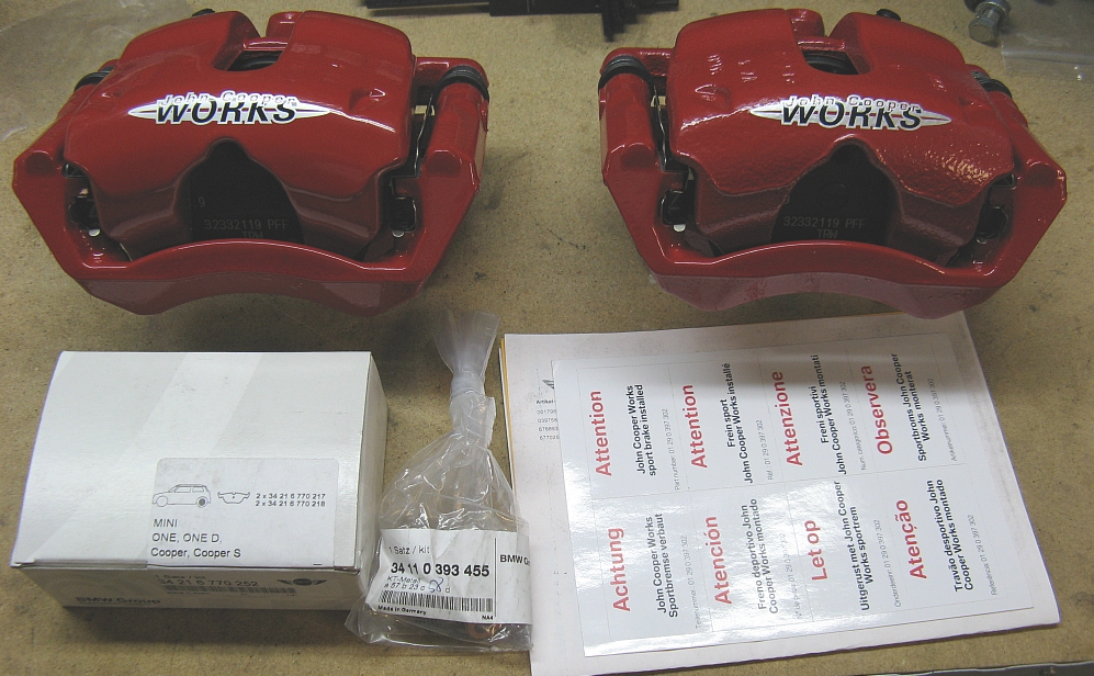
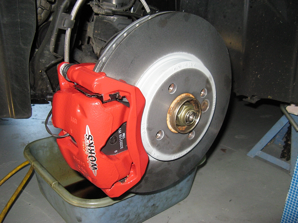
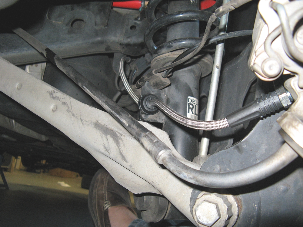
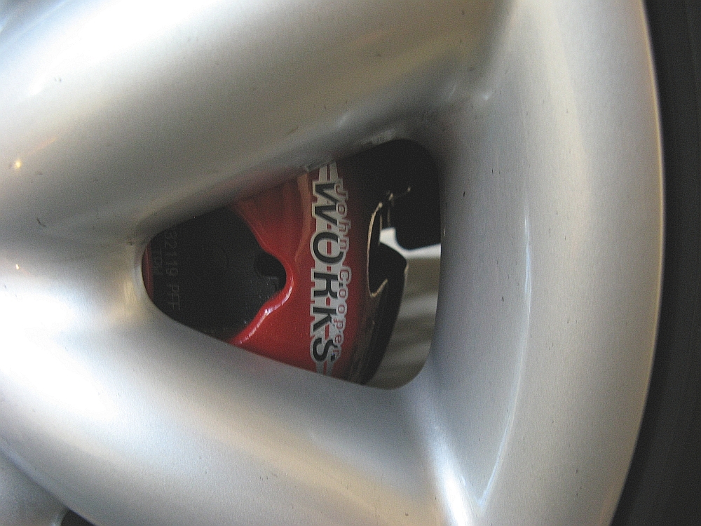
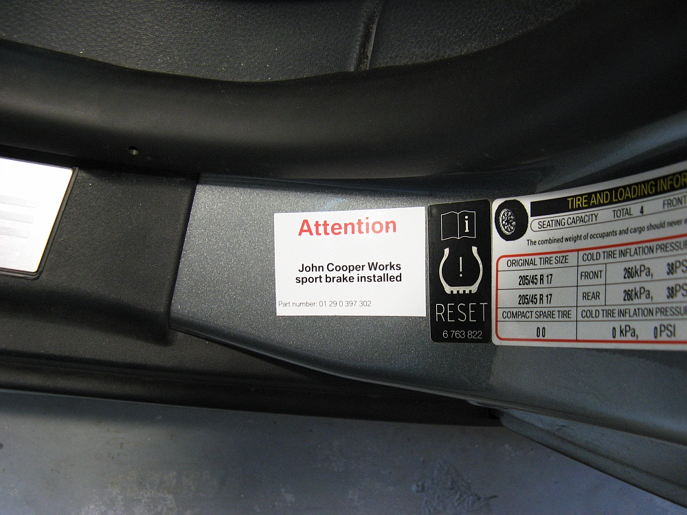
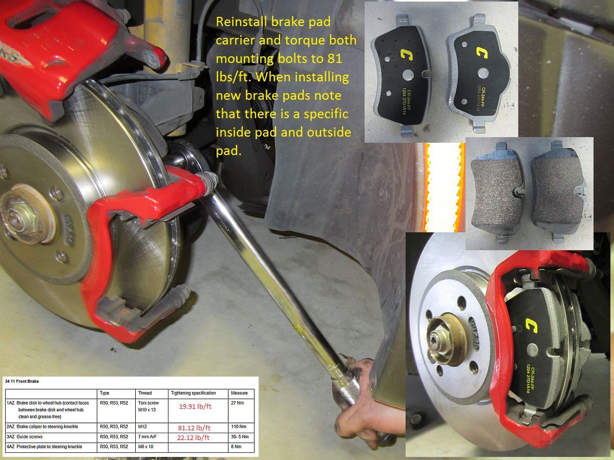
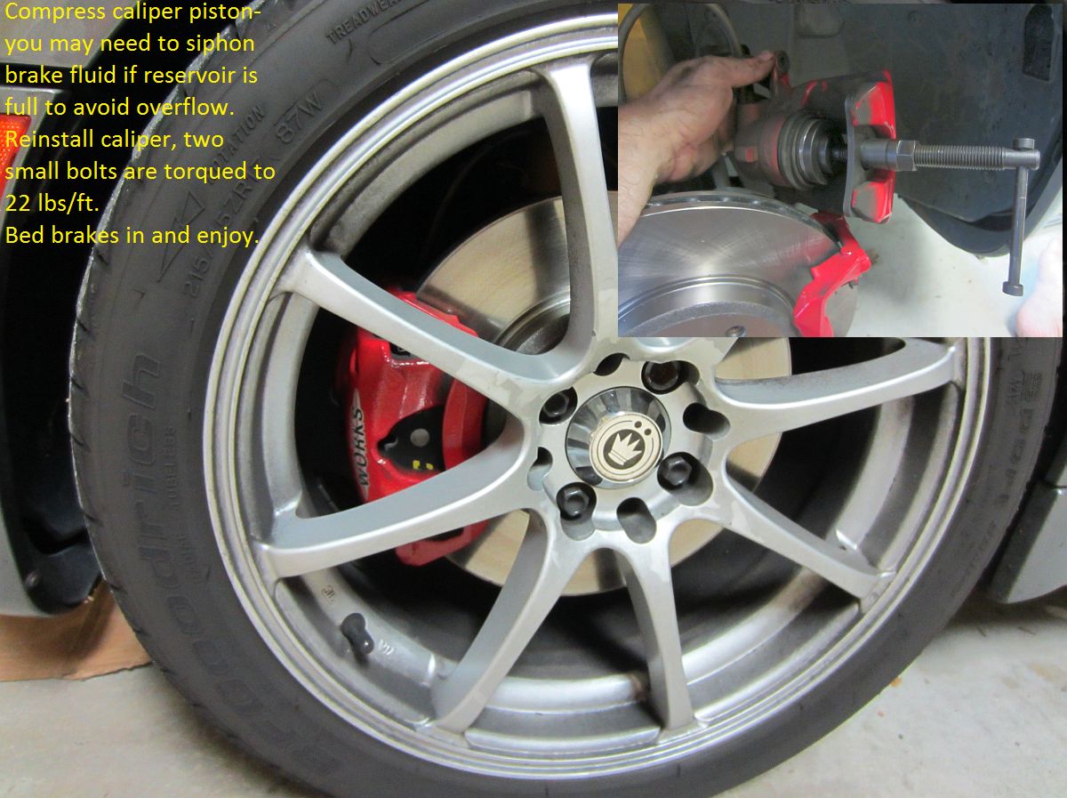
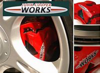
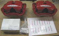
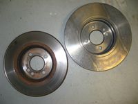
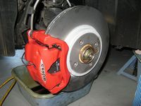
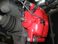
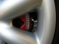
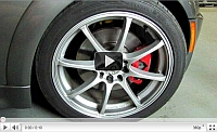
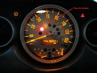
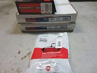
John Cooper Works (JCW) R53 Sport Brake package from Classic Mini installed. Jayson is the NAM contact at Classic for discounted parts, phone 440-585-9950 or email bmwparts@driveclassic.com - ask for the North American Motoring forum discount (~20%).
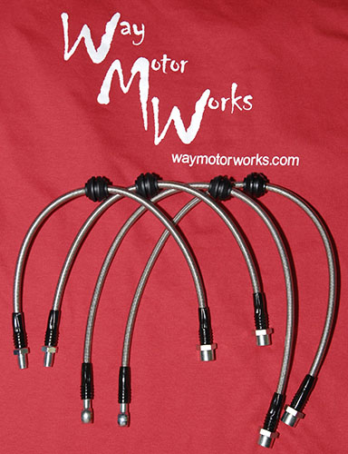
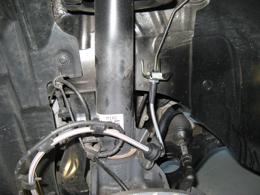
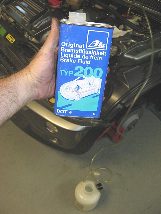
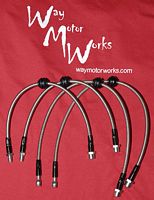
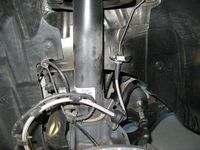
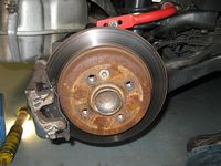
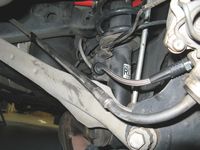
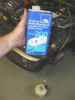
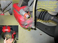
The JCW R53 brake system includes new larger front calipers/rotors/pads and rear pads for a matched system- original rotors are 276mmx22mm, new JCW rotors are 294mmx22mm. I also decided it was a good time to install stainless steel brake lines from Way Motor Works and flush the lines with ATE Typ 200 brake fluid. The brake bleeding was the worst part, usually the Motive pressure bleeder makes a full system bleed a half hour job, but it seems air snuck in somewhere so the Motive bleed was followed by the wife-manual-pump-and-hold-while-I-wrench bleed. I'll let you know after the prescribed 200 mile break in how these brakes are
Motoring File JCW R53 Brake details can be found HERE and Motoring File JCW R53 Brake review can be found HERE.
Mini installation instructions for the JCW R53 brakes can be found HERE.
My installation write-up can be found HERE:
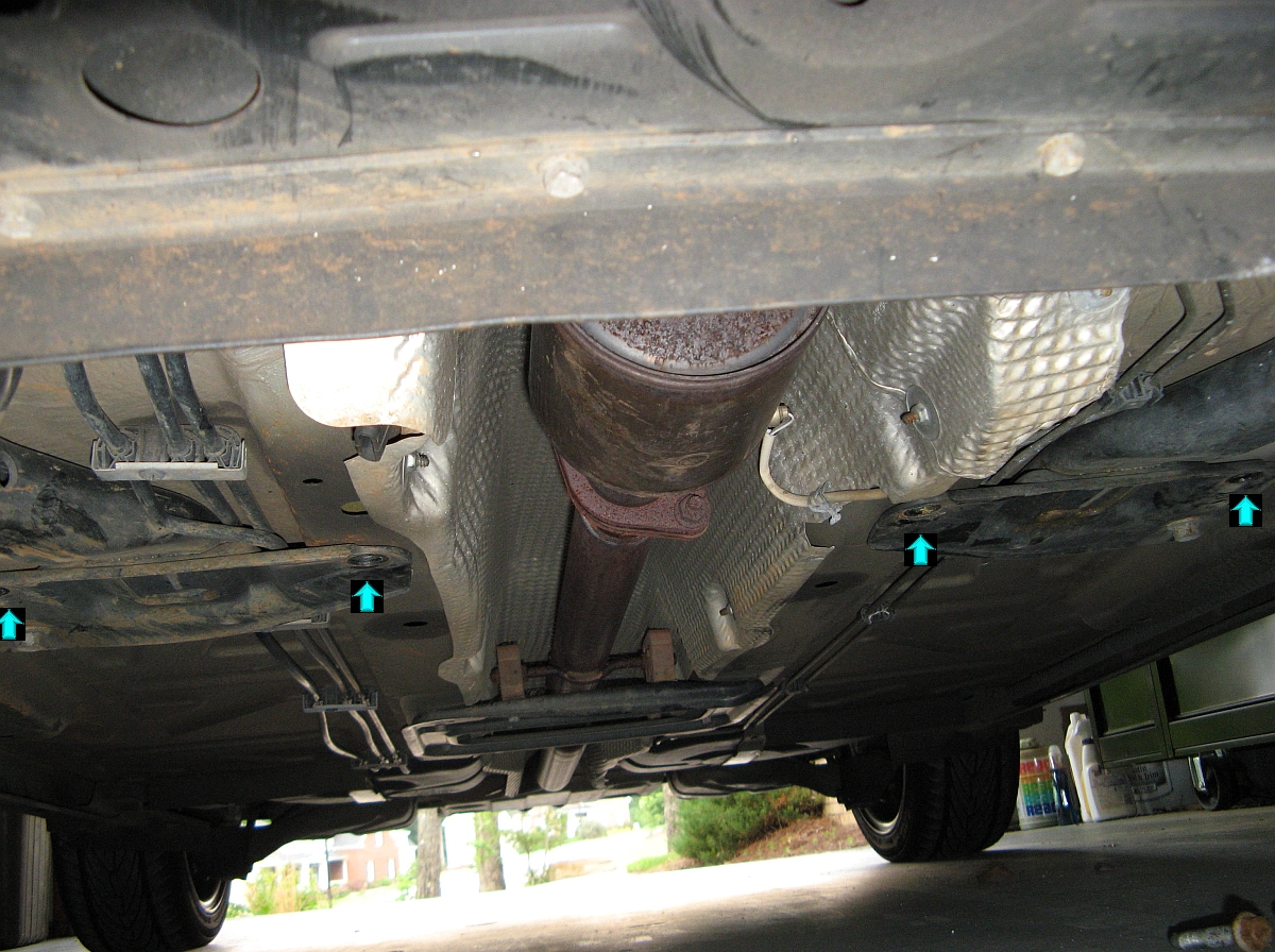
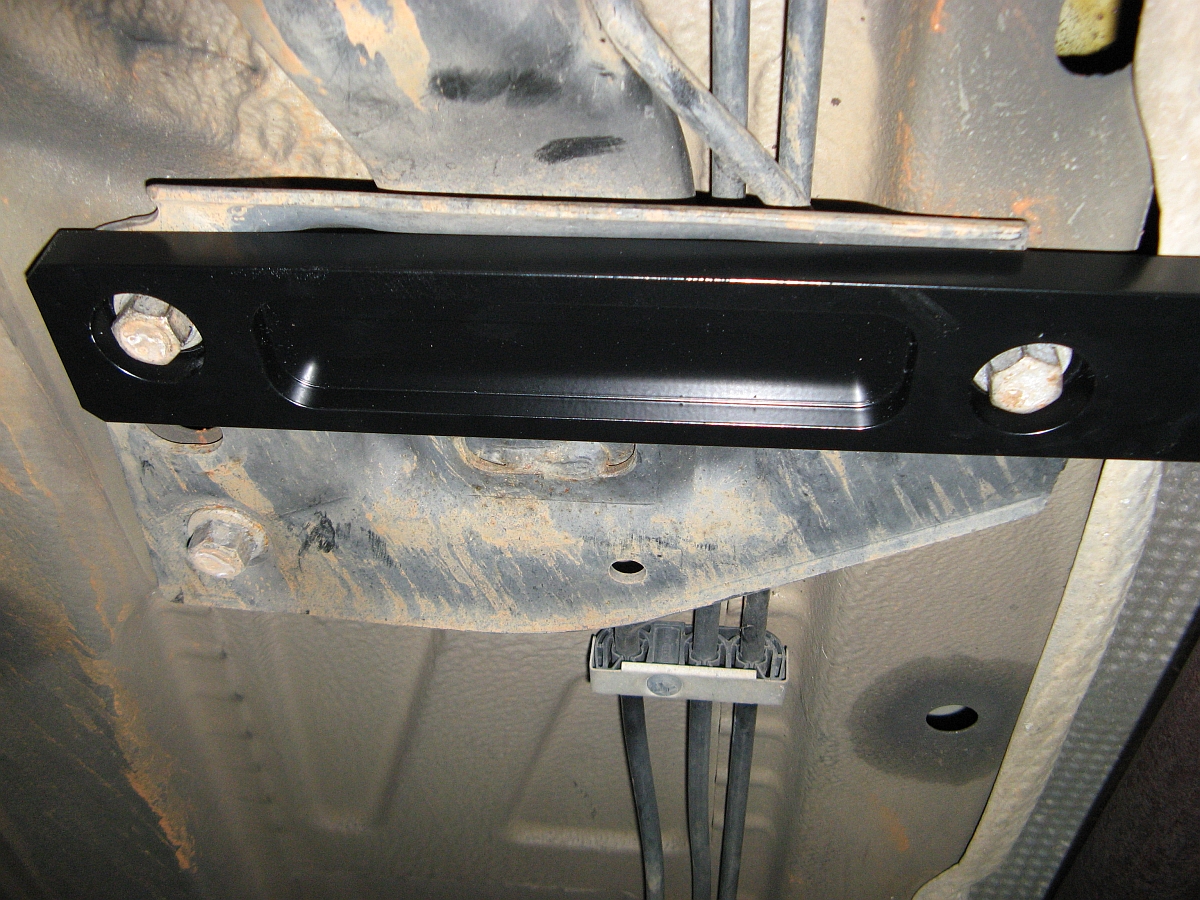
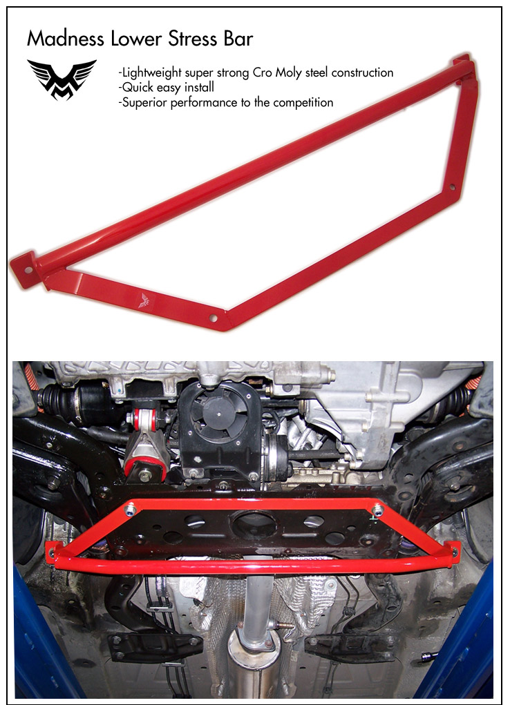
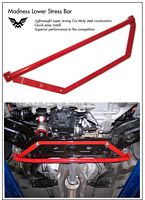
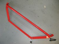
Lower stress bar/brace from Mini-Madness installed,the thread on NAM that convinced me to try the already installed TT lower mid brace and the MM brace paired can be found HERE.
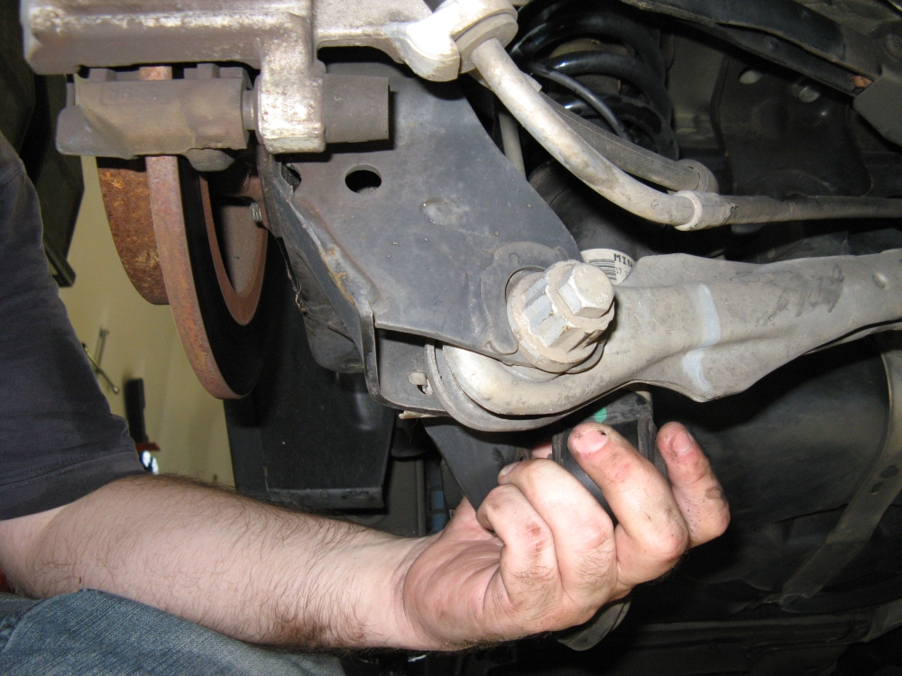
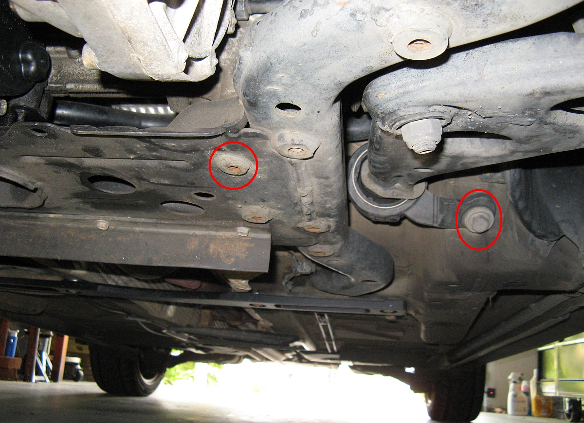
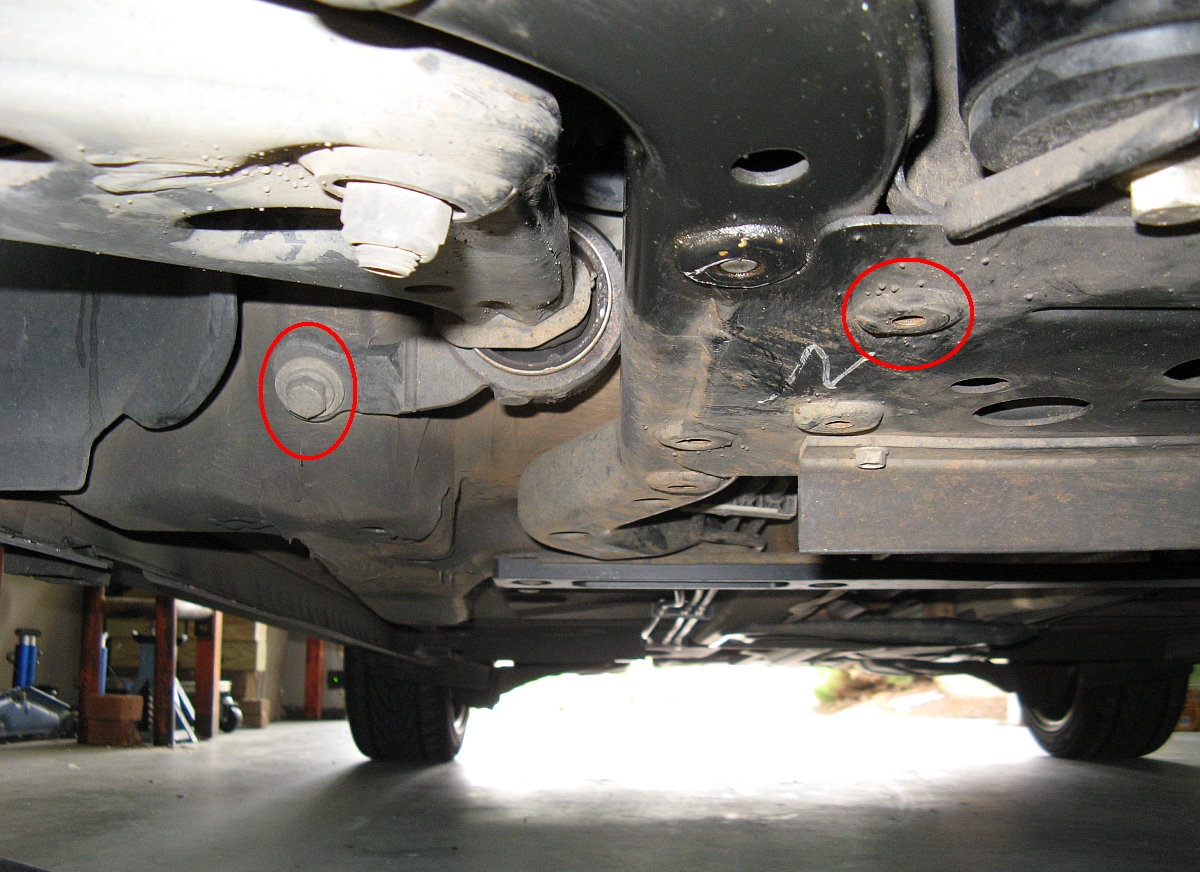
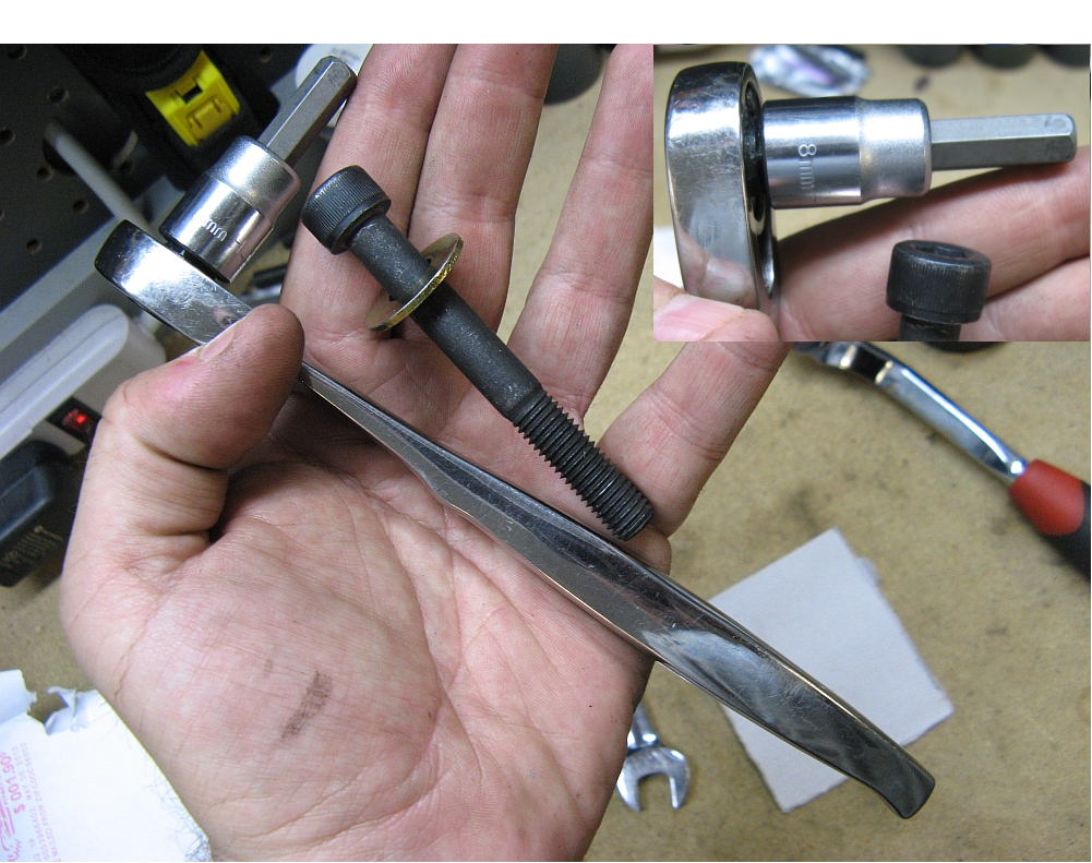
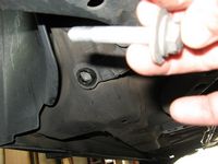
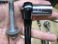
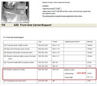
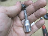
I purchased the new brace from the NAM classifieds but since it came without hardware, I sourced that from MM. No instructions were included and I could not find any on the web but once you see where it goes it is fairly easy to see what needs to happen. After I had the car up on Rhino Ramps (parking brake on, rear wheels chocked), the control arm bushing bracket to body bolts on either side were removed using a 16mm socket/ratchet. These bolts are one time use, angle torque bolts (aka torque-to-yield bolts)- I have the TIS spec below, ~43.5 lb/ft and then 90 degrees additional rotation. I held the bar in place with one hand while installing the replacement hex head bolts with washers using a 7mm HEX socket/ratchet, these are installed loosely so the front bolt studs will line up and go in- If you cannot line them up and start them in the holes than the rear bolts are not loose enough to give you some play. The bolt studs have a 5mm HEX head used to install them/adjust them for fit with the nut, mine were able to hand thread in. I threaded these in so that they would be flush with the top of the nuts when tightened. After the studs are installed, the nuts can be installed hand tight. After using a torque wrench to tighten the rear mounting/control arm bushing mount bolts, a 13mm socket/ratchet was used to tighten the front bolts- no torque spec available so I just made sure they were subjectively tight (not gorilla tight). This brace should work well in concert with the other braces.


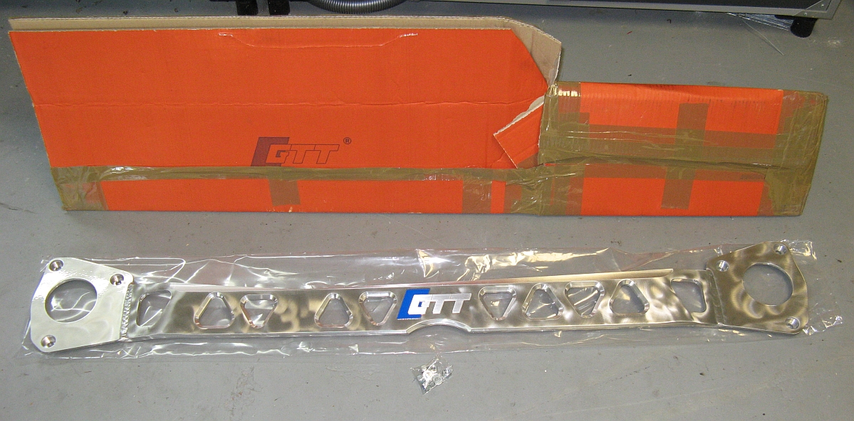
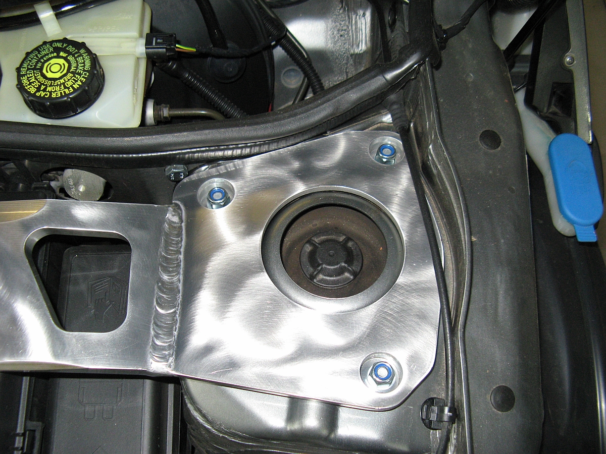
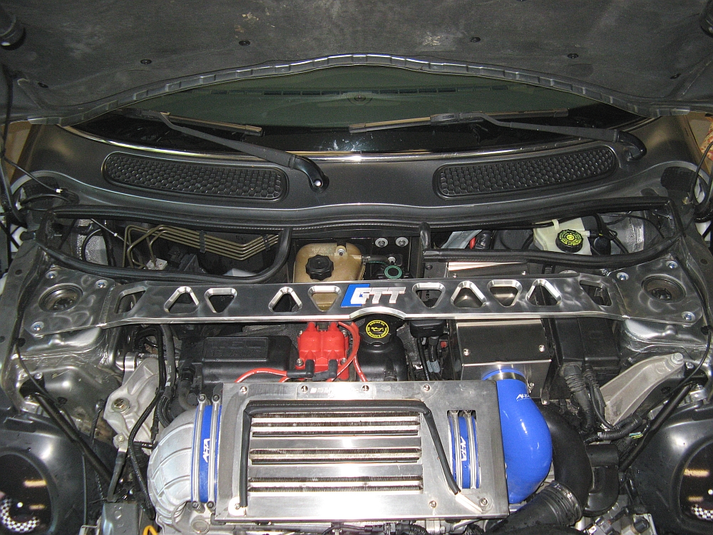
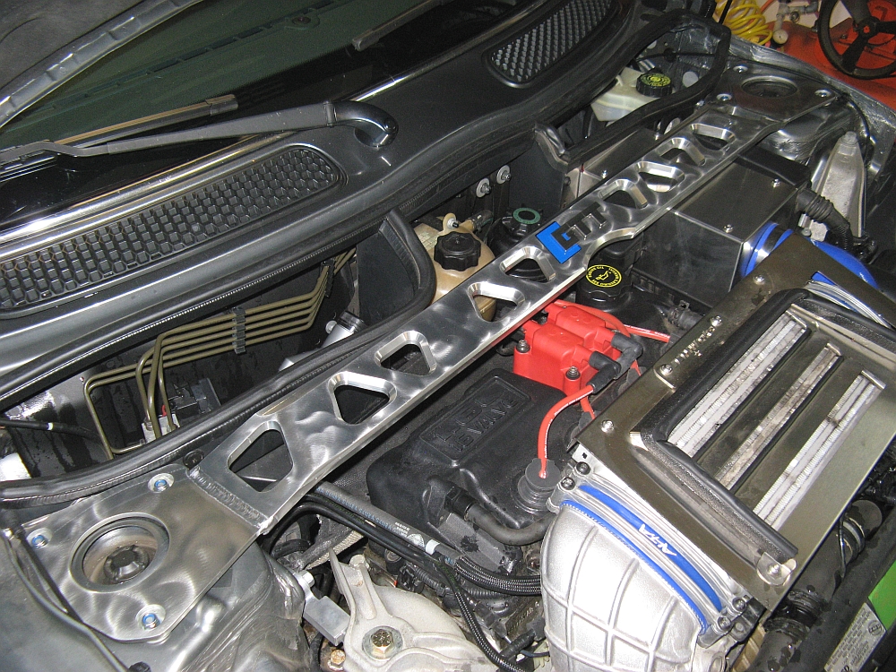
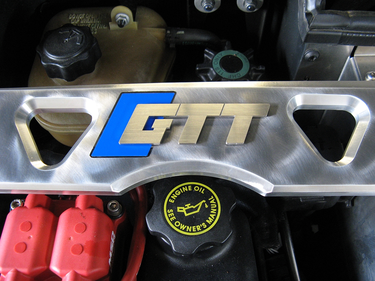
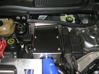
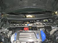
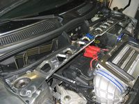
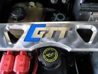
GT Tuning Aerobox Strutbrace installed, GTT installation instructions HERE. The Mini2 intro thread is HERE.
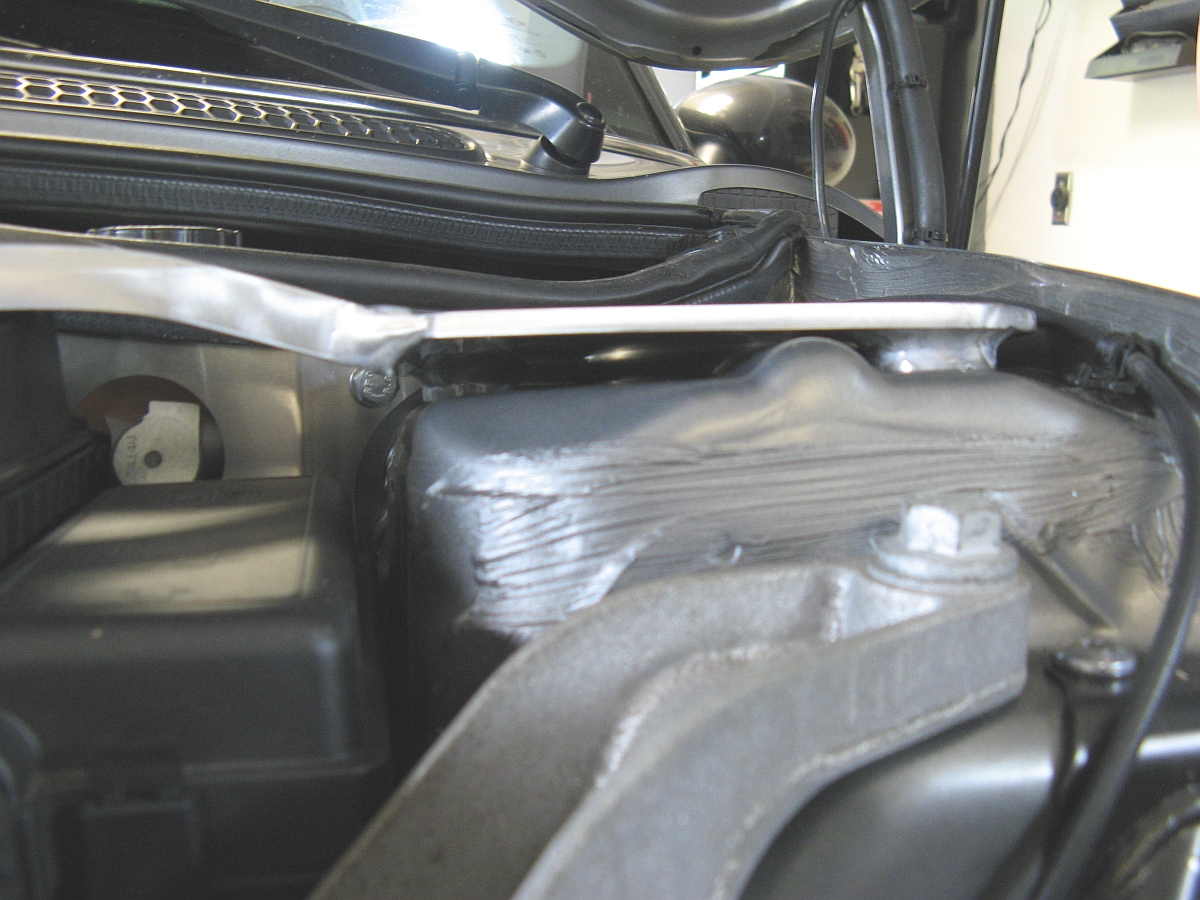
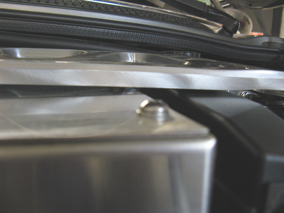
This brace is almost too nice to install on the car and I briefly thought about hanging it on the garage wall. Easy installation- make sure car is on ground with wheels loaded, remove three bolts per side from the strut towers (six total) using a 13mm socket/ratchet, place brace in place being careful not to pinch the hood release cables, install new Nylock bolts and washers provided, tighten to 25 lbs/ft. As noted in the GTT instructions, the brace is designed to not interfere with the hood closing (a problem that other bars have) and is designed to make contact with the airbox to allow for that. The DDMW airbox I have installed would have cleared but one of the bolts for the lid was in a place that lines it up with the bar so it is just touching, no rattling or worries though and the hood closes perfectly with no interference. There is a notch cutout for access to the oil filler cap, I have put oil in since installation and can say it works well enough. This bar is SOLID and the car feels more solid post install.

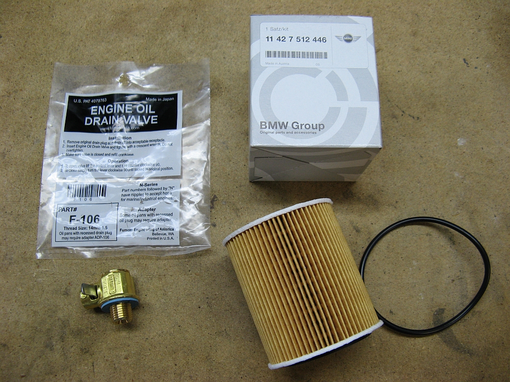
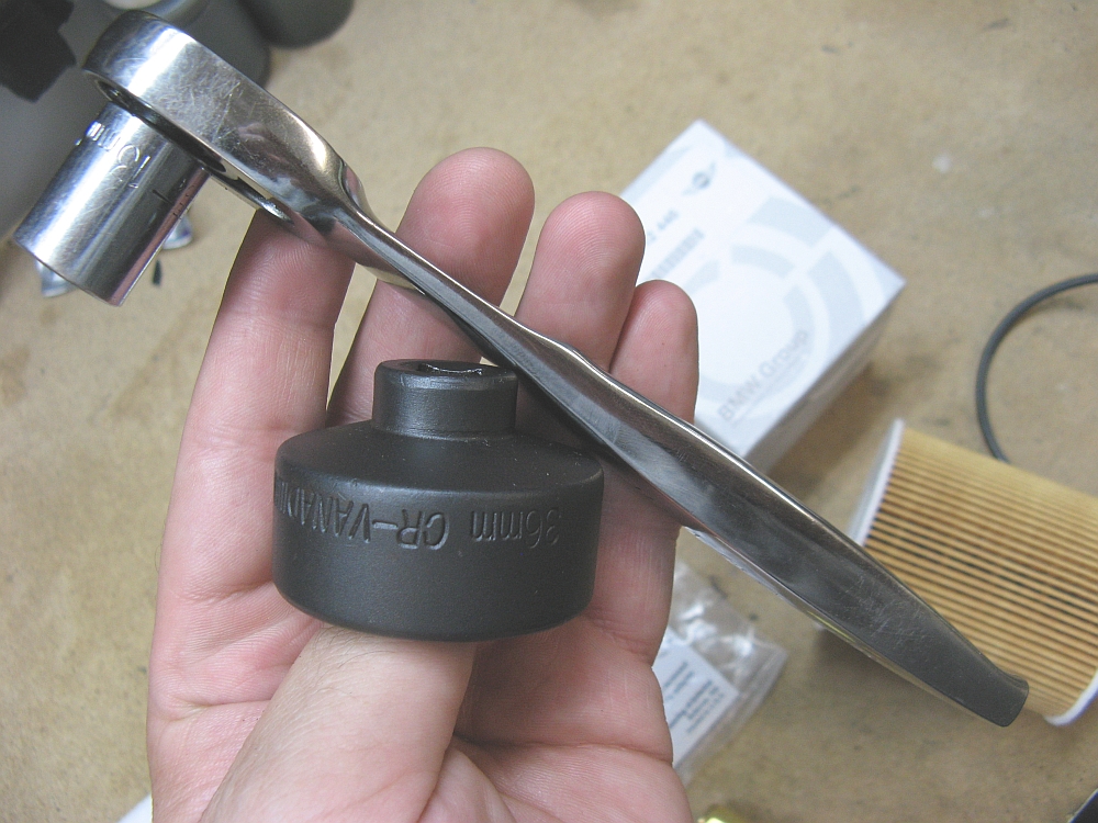
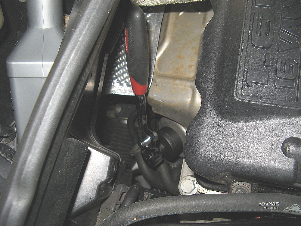
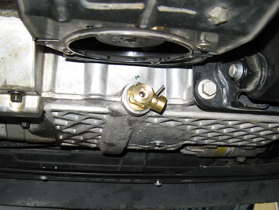
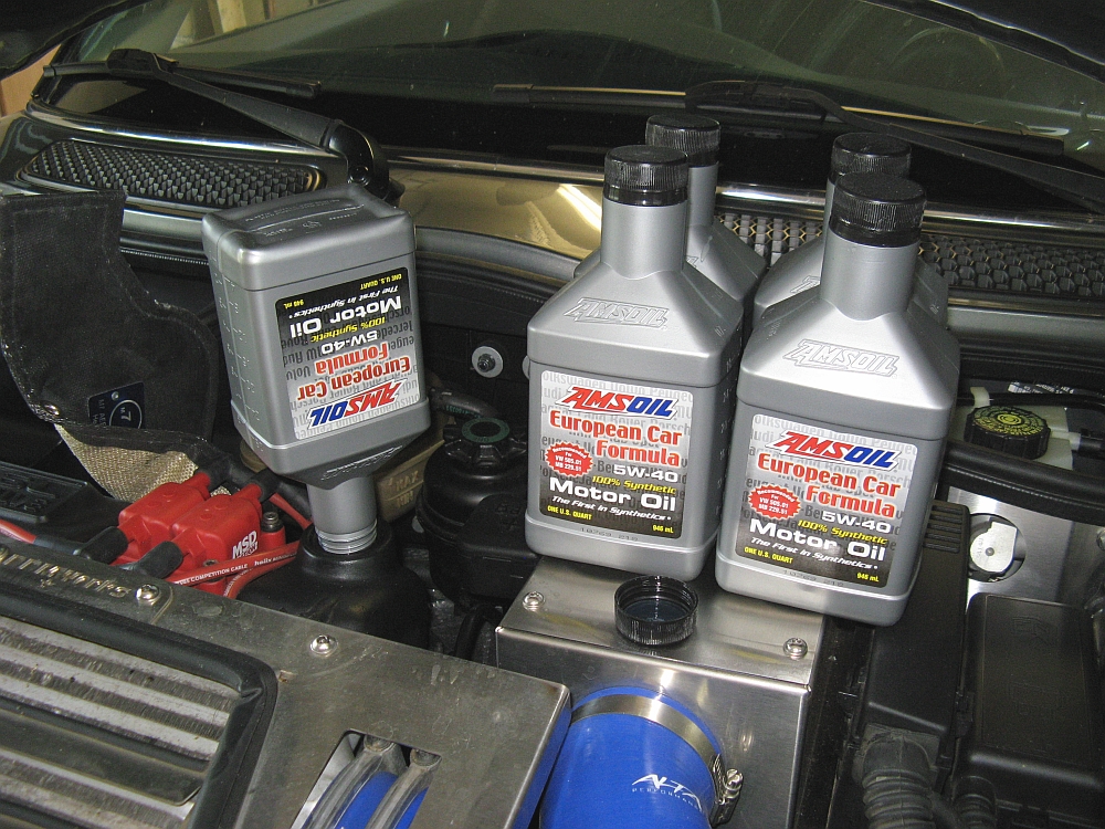
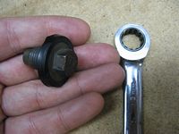
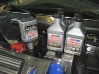
While installing both of the braces above I also changed the oil for my first time. In anticipation of this I had already purchased the BMW/Mini Oil Filter (P/N 11427512446) and a Fumoto Oil Drain Valve (P/N F-106) to replace the oil drain bolt. I also had some Amsoil 5w40 European Synthetic left over from my VW days and decided to use this for the Mini (BMW Synthetic 5w30, P/N 07510017866, is factory fill).
I also found Randy's DIY guide helpful.
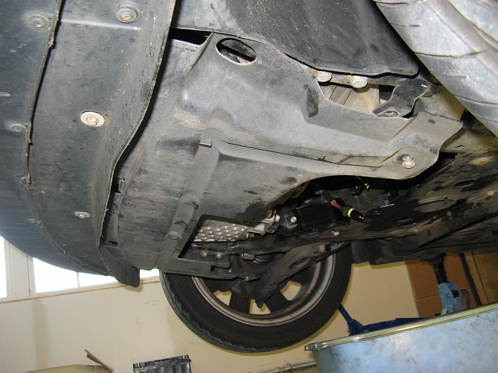
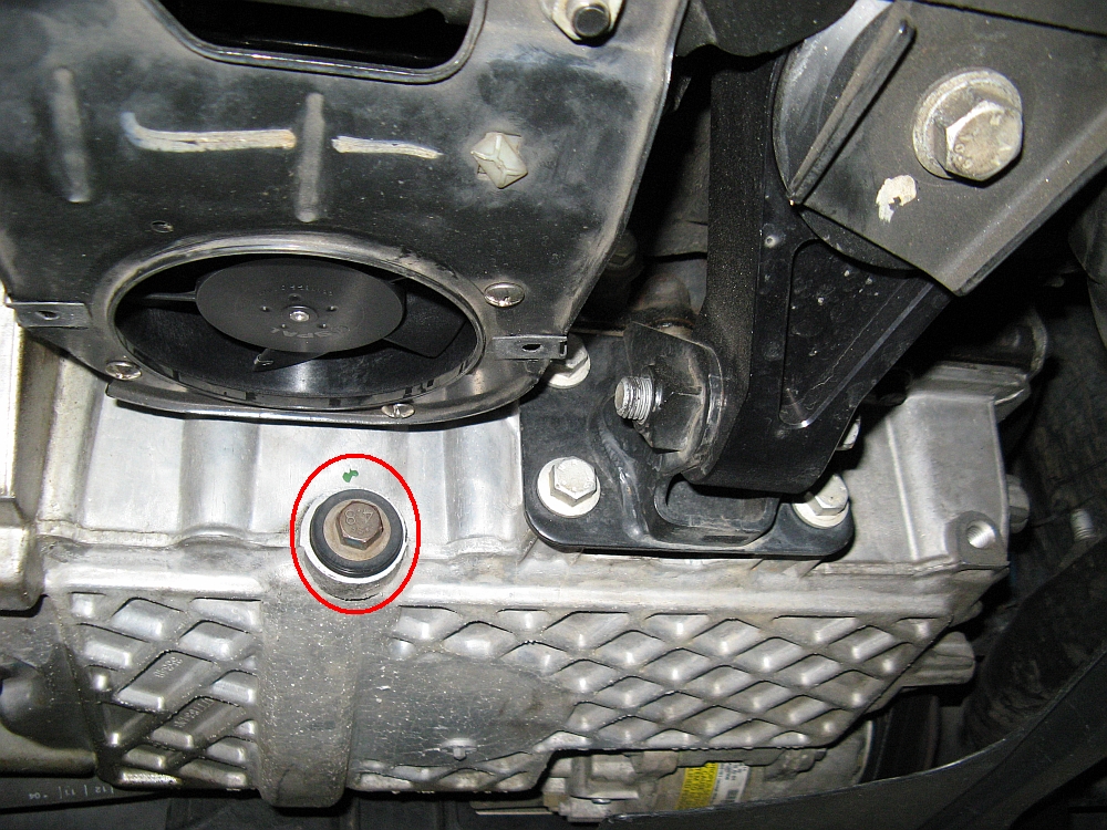
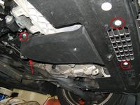
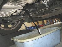
To start I took the car for a half hour drive to get the oil nice and warm- not only will it drain faster and more completely but the particulate that settles is now suspended in the oil when I drain it. After driving the car up on Rhino ramps and chocking the rear wheels, I removed the PSP fan duct using a Phillips head screwdriver to release the four screw retainers. With this out of the way I was able to access the oil drain bolt at the rear of the oil pan.
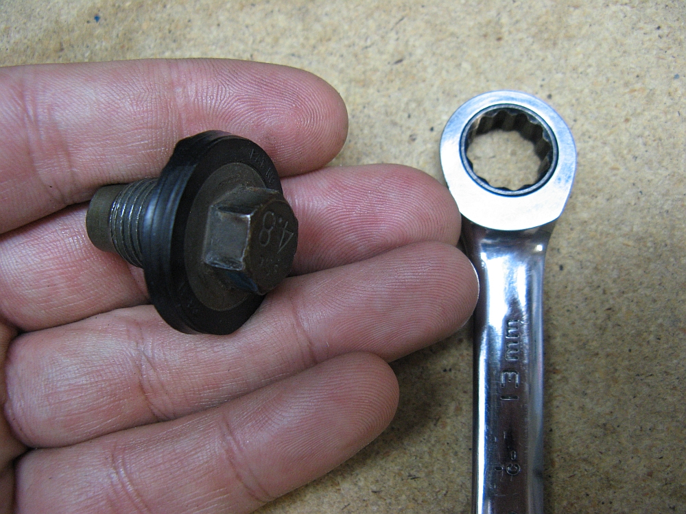
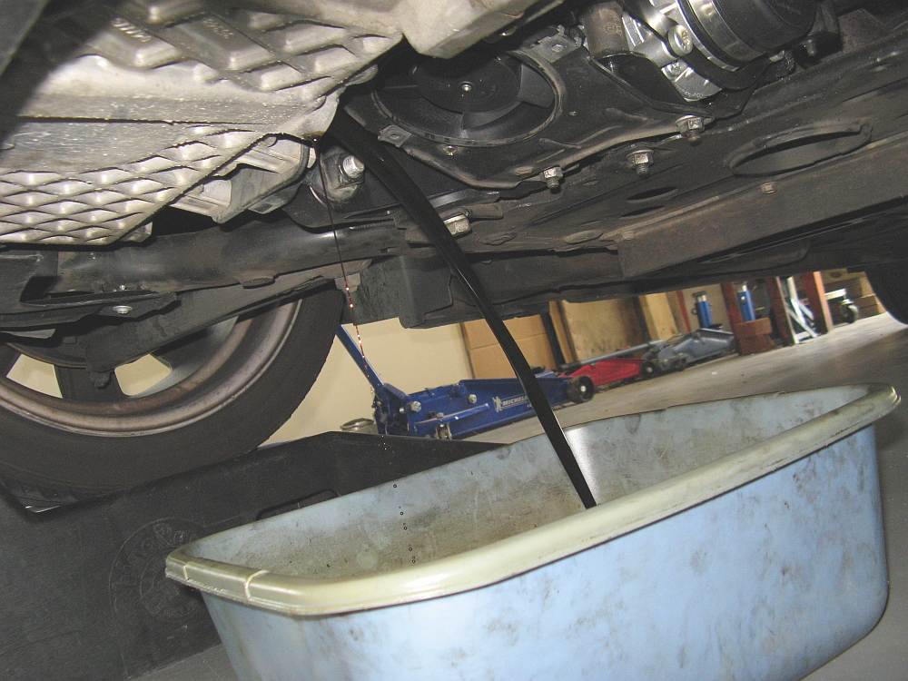
Placing a drain pan underneath, I removed the drain bolt using a 13mm wrench- the drain bolt and oil will be HOT so if you have some rubber gloves, that may protect your hand somewhat- please don't hold me responsible if you burn yourself
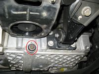
Time to go back underneath the car, the Fumoto valve was installed hand tight and then 1/4 of a turn with a 19mm wrench. Before installing the valve you may want to open and close the valve a few times to make it easier the first time you use it. To bring the oil up to the full mark, I used 5 quarts of Amsoil 5w40. Last but not least, start the car and let it idle for a while, make sure there are no leaks, and replace the PSP fan shroud if your car has one.
I usually wait for the oil counter to read 7500 miles left before I do an oil change and then again when it reaches 0, two for every single BMW/Mini recommended oil change. When you get to zero and want to reset the oil service counter you can follow the instructions HERE.


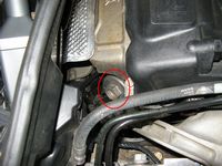
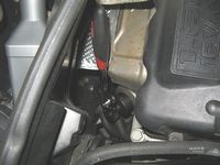
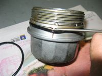

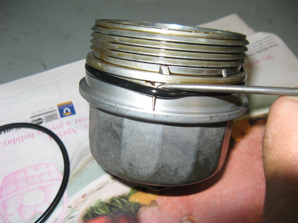
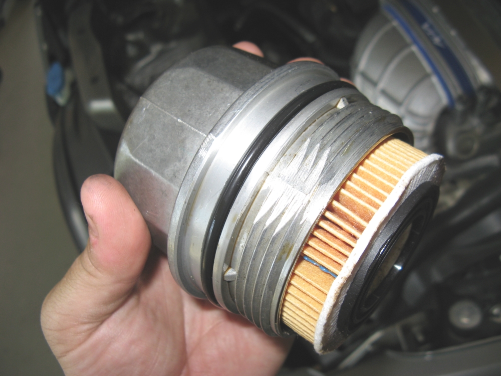
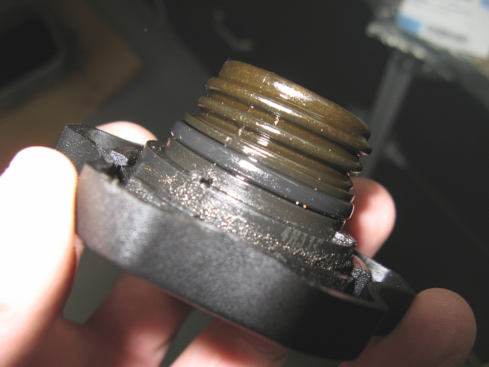
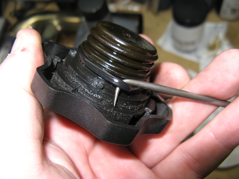
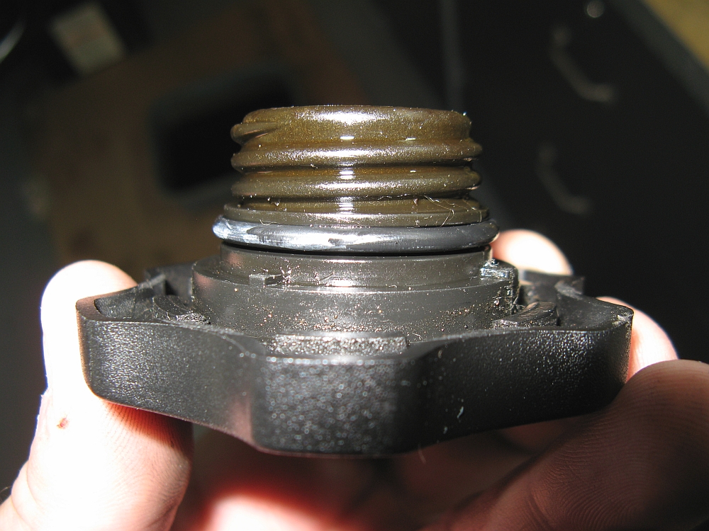
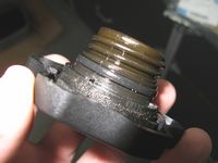
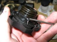
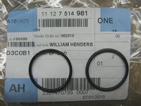
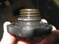
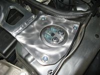
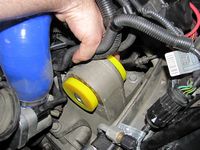
If your car has some miles/years on it and you notice oil residue around the oil filler cap, chances are it is time to replace the oil filler cap o-ring seal. After it cooks from the heat of the motor over time it starts to lose its rubber characteristics to become more like plastic and flattens out a bit, note the before and after picture differences. Easily replaced with P/N 11127514981 :
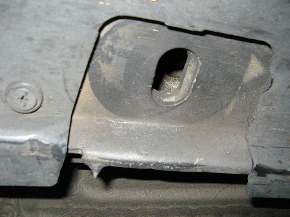
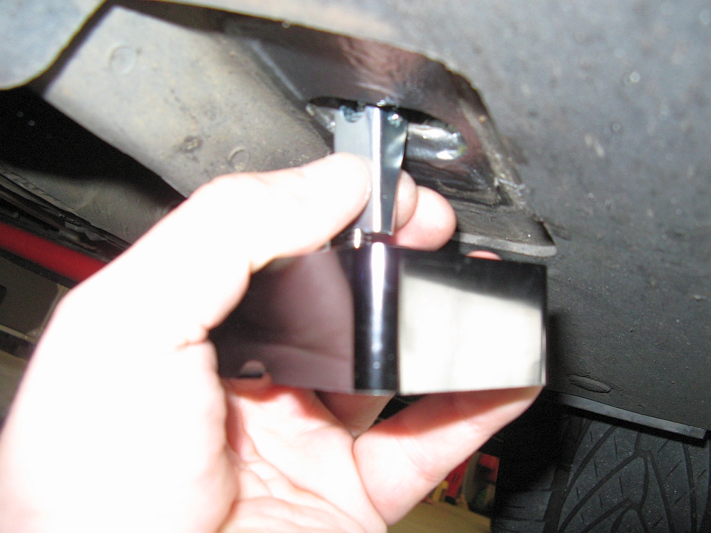
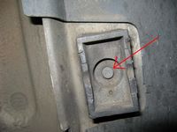
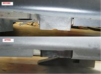
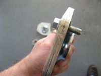
TSW Billet Jack Points from Way Motor Works installed- TSW installation instructions HERE.
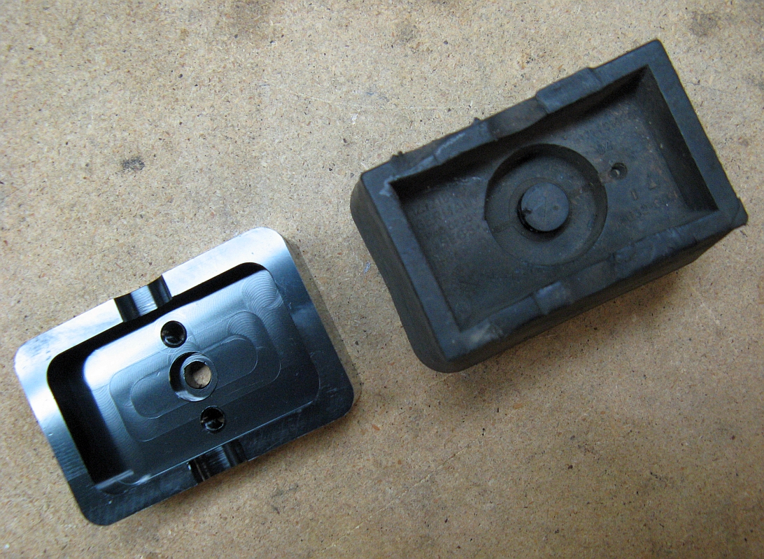
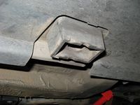
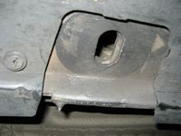
My car came with 3 of 4 jack points, from the side skirt damage I am guessing the other one decided to come off while the car was being jacked up. The OE plastic jack points hang down low under the car begging to be ripped off. I decided rather than waste money on the single OE jack point I would just upgrade to the TSW billet jack points- Not only lower profile but more secure mounting. The jack points come with everything needed to install them, even the LokTite.
I started by removing the plastic OE jack points, there is a plastic insert that is pushed up into the center for a pressure fit. I used a flat head screwdriver and/or flat prybar between the jack point and the car to pry them down, this resulted in the pin being pulled out and low enough that I could use a screwdriver to pry the center pin the rest of the way out....you could also use pliers to pull the pin out for this step. Once the center pin was removed it took one good pull and the OE jack point was off.
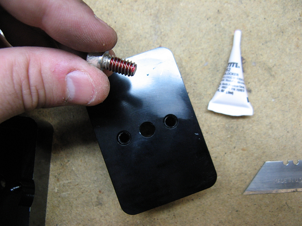
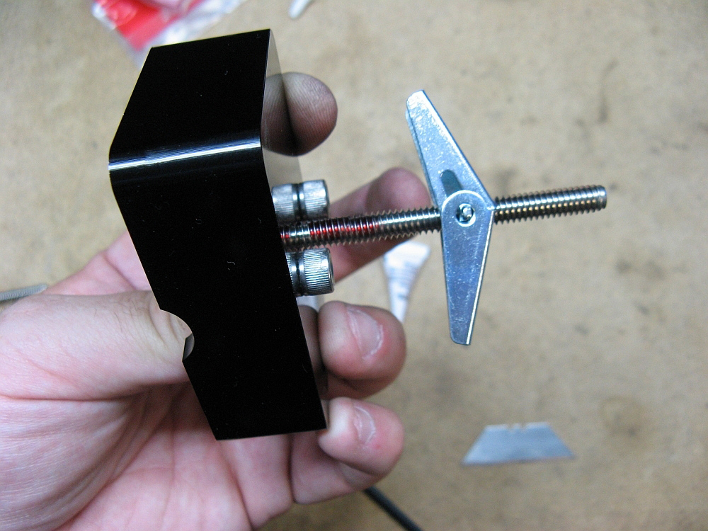
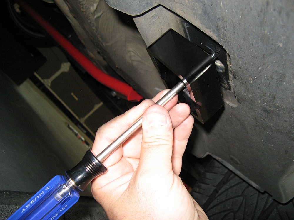
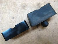
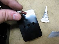
After the OE jack points were removed I went back to the bench to get the TSW jack points ready for installation. The smaller HEX head bolts are inserted in the outer holes and tightened using a 3/16" HEX wrench after applying LokTite. I repeated this step until all four points were completed. These two bolts serve to align the jack point with the slot at the mounting point on the car. The center bolt was then placed through the center hole from the inside and the toggle nuts threaded about halfway down- LokTite applied towards the base of the threads (from 1/2 to 1 inches from the bottom) where the toggle nut will end up when tightened during installation.
The toggle nut is pinched and pushed through the mounting slot on the car. Tightening involves pulling the jack point down to apply pressure to the toggle nut while tightening the bolt with a Phillips head screwdriver. As the bolt is tightened make sure the outer HEX screws seat in the slot and hold the jack point square during final tightening. It is VERY easy to strip out the toggle nut so get it tight enough that the jack point will not twist but not gorilla tight. Repeat for remaining jack points.
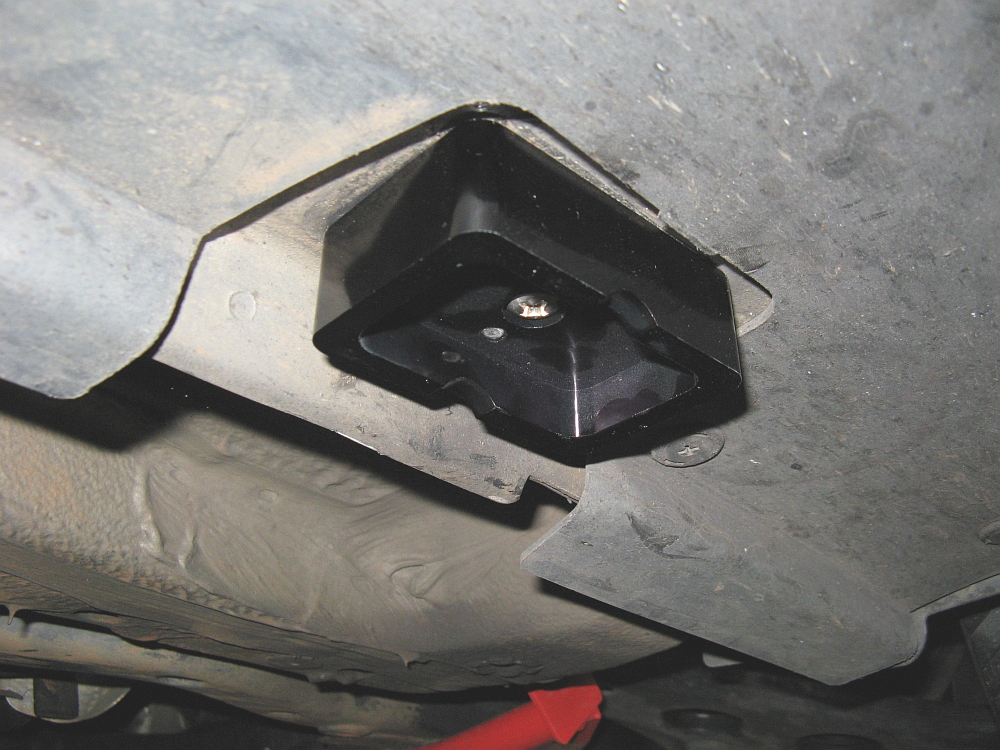
It is easy to see that these will not be as easy to rip off since they are tucked in tighter to the car body and they should last a while longer as well.


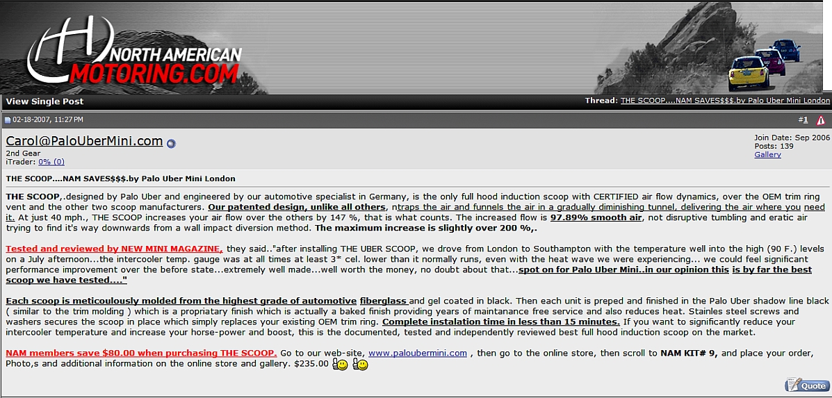
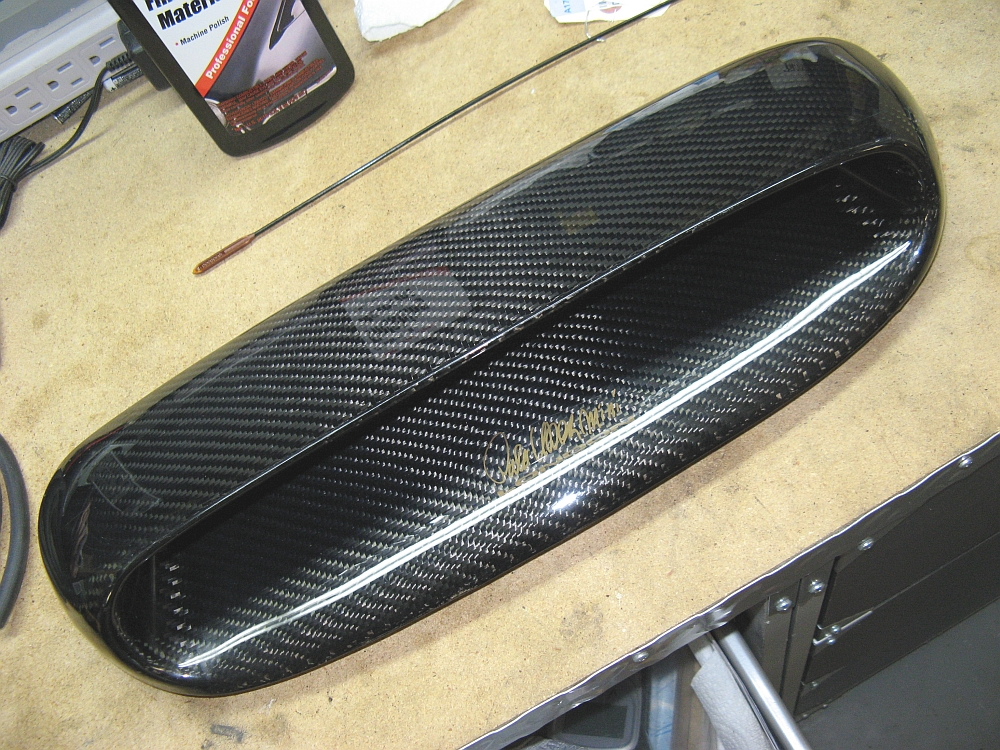
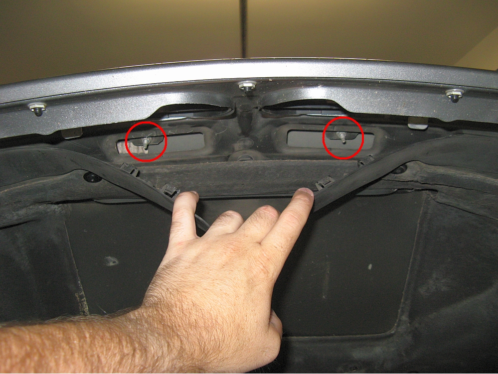
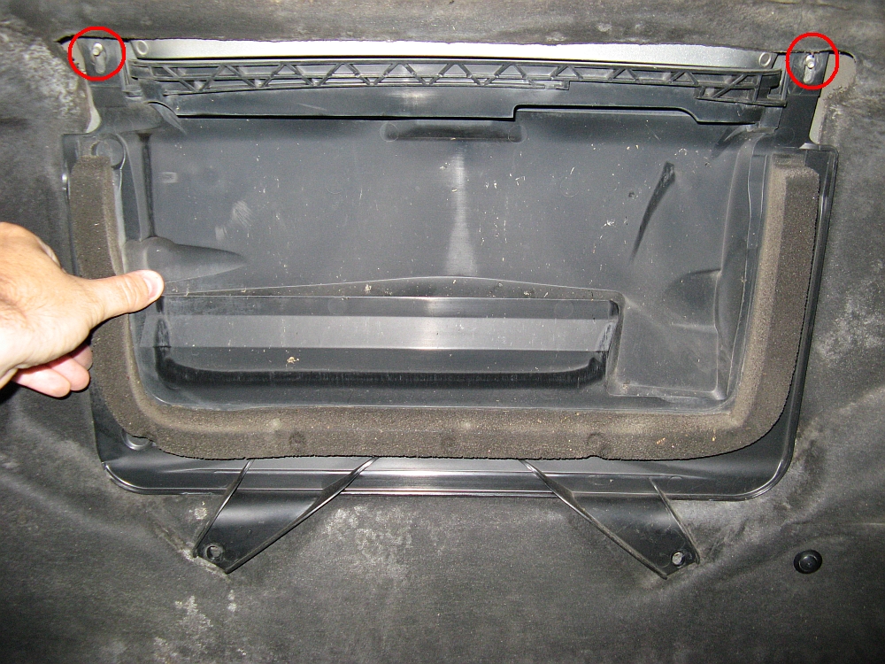
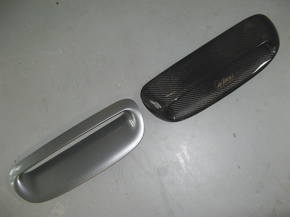
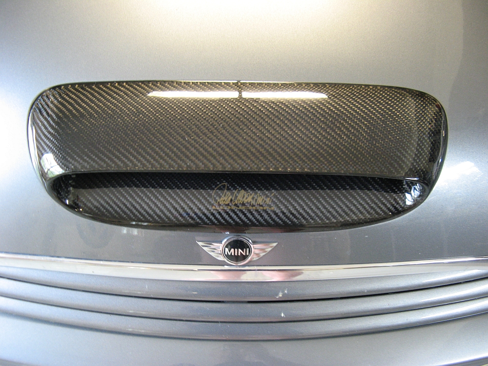
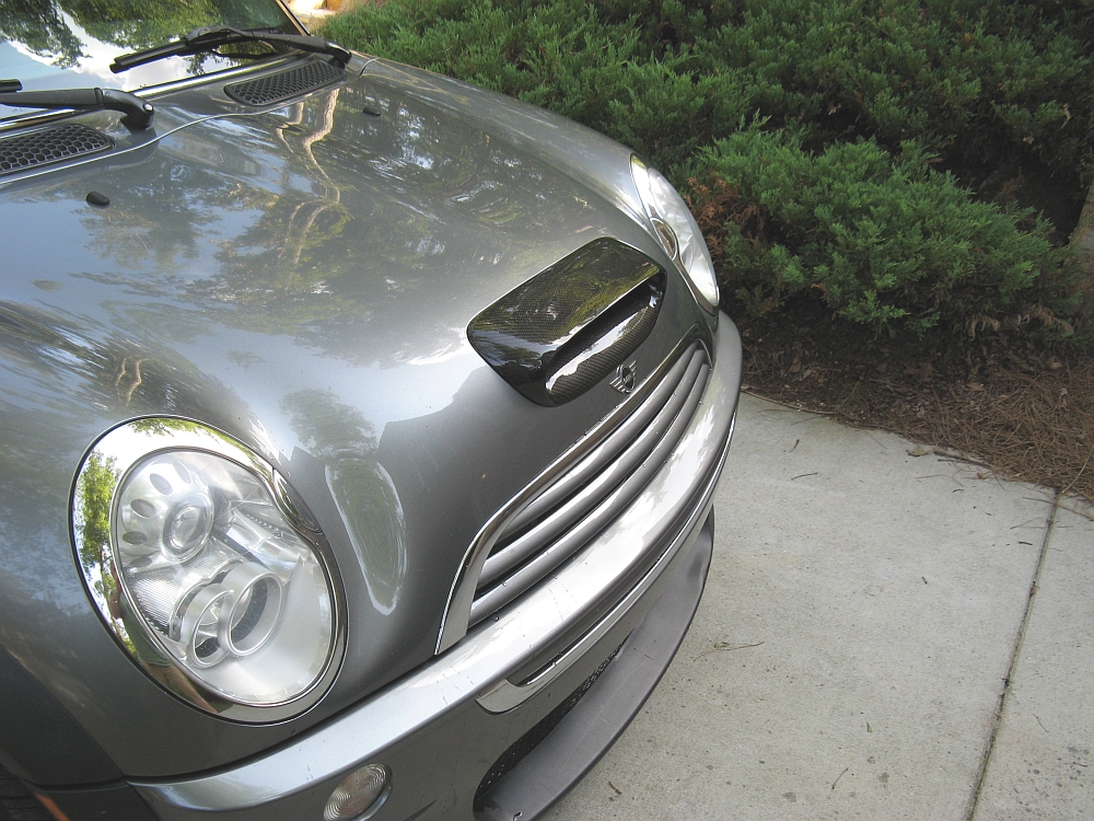
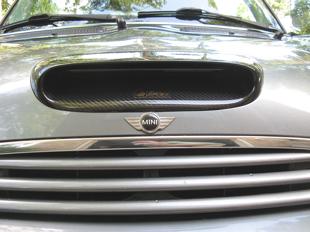
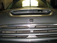
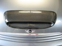
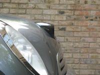
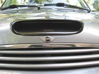
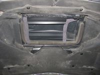
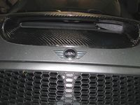
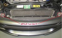
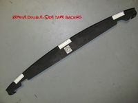
I had been looking at M7 and Voltage hood scoops but in carbon fiber they were big $$$ and made to order. I also had seen some Palo Uber London hood scoops but the company is no longer in business. I was perusing Craig's List one day and happened to find one on the other coast, it was a Palo Uber CF scoop. After some discussion over email with the seller I decided to buy it and try it out. It was in great shape and the price was right, I am still deciding if I like it or not.
The look is definitely more aggressive and I like (love) carbon fiber.....it was easily installed, two plastic pieces are unsnapped and removed to access the forward bolts/nuts, the rear bolts/nuts are shared with the plastic intercooler air guide under the hood. Some have removed this piece entirely due to poor fitment with the aftermarket scoops, I was able to leave mine in place with no issue.


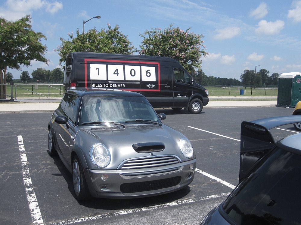
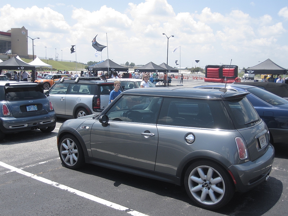
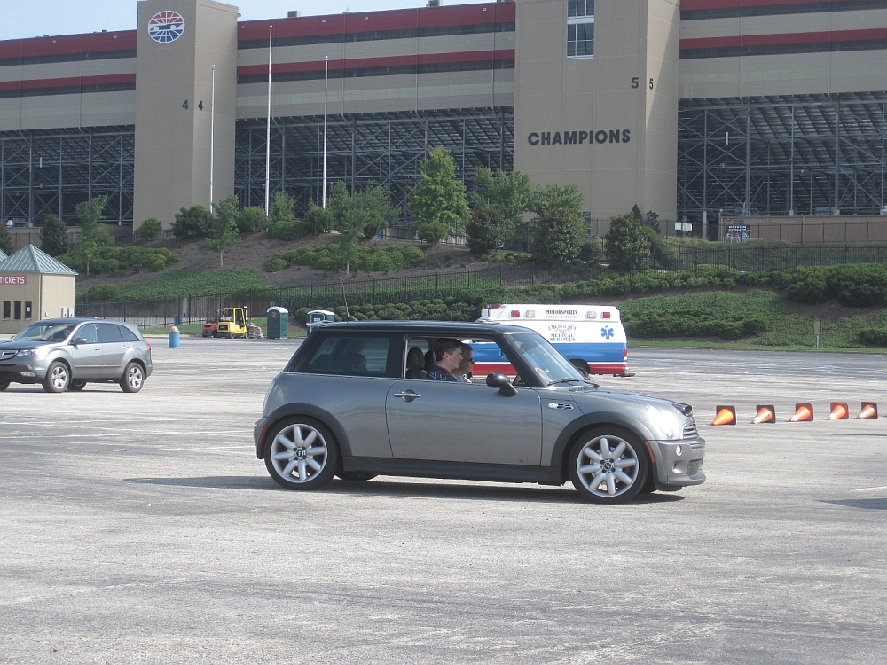
Attended the MiniCross at Mini Takes The States 2010 at the Atlanta Motor Speedway on August 7th. My wife, my son, and I all got a chance to drive/ride in the new R56 Minis on an autocross course and at the end of the event the organizers even let guests have some fun in their own cars on the course before they tore it down.....lots of fun but HOT. Big THANKS to the local dealerships and Mini for putting this together!


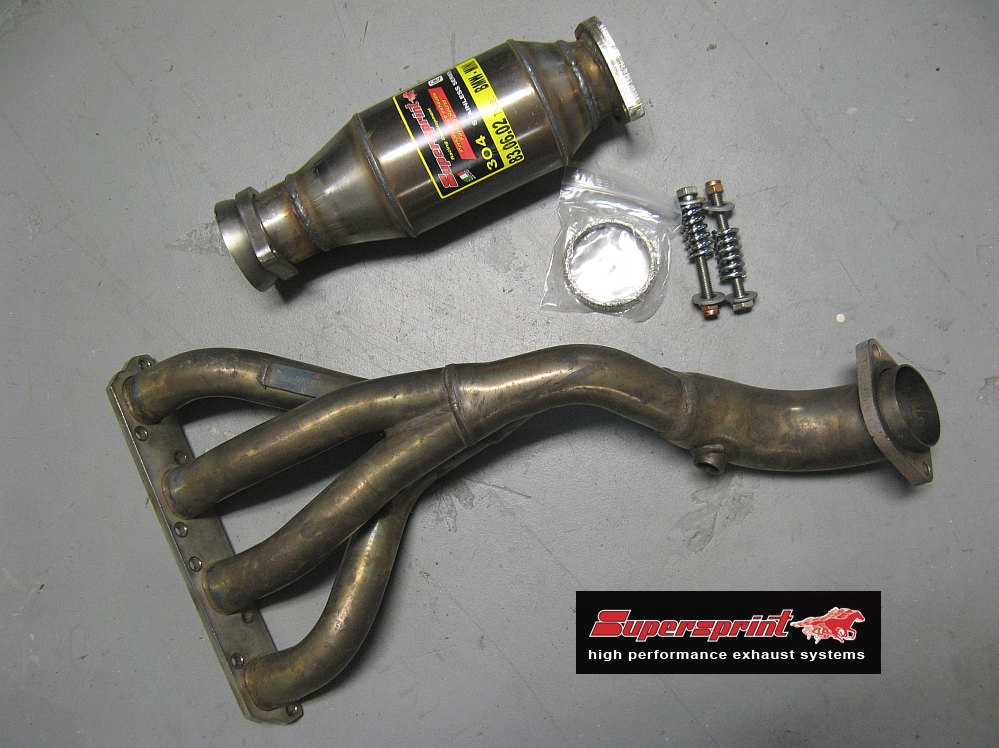
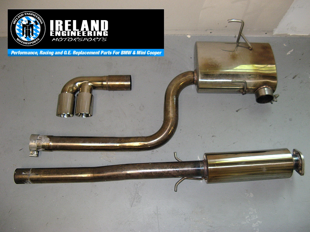
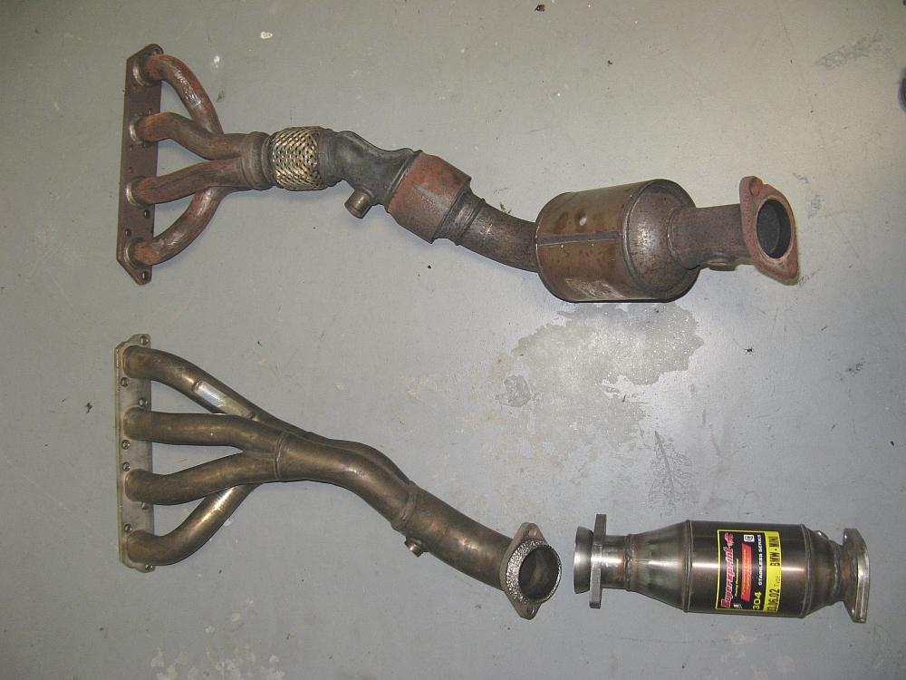
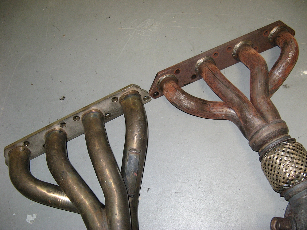
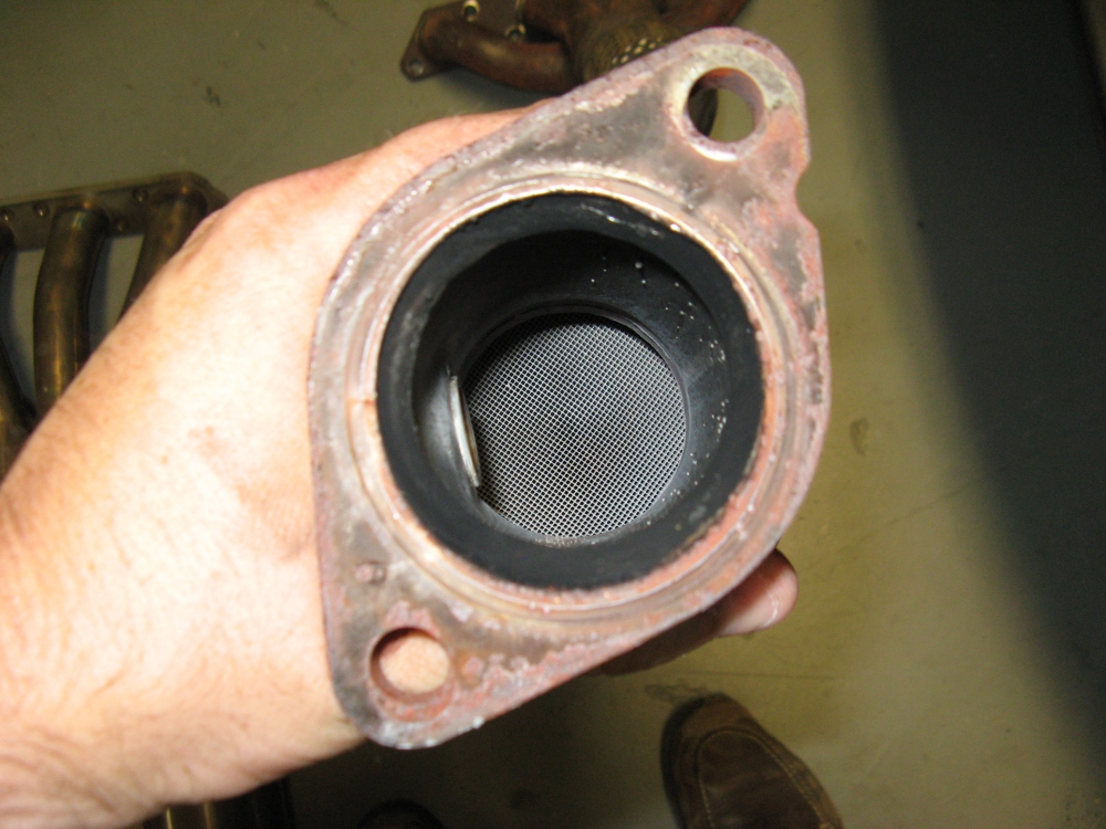
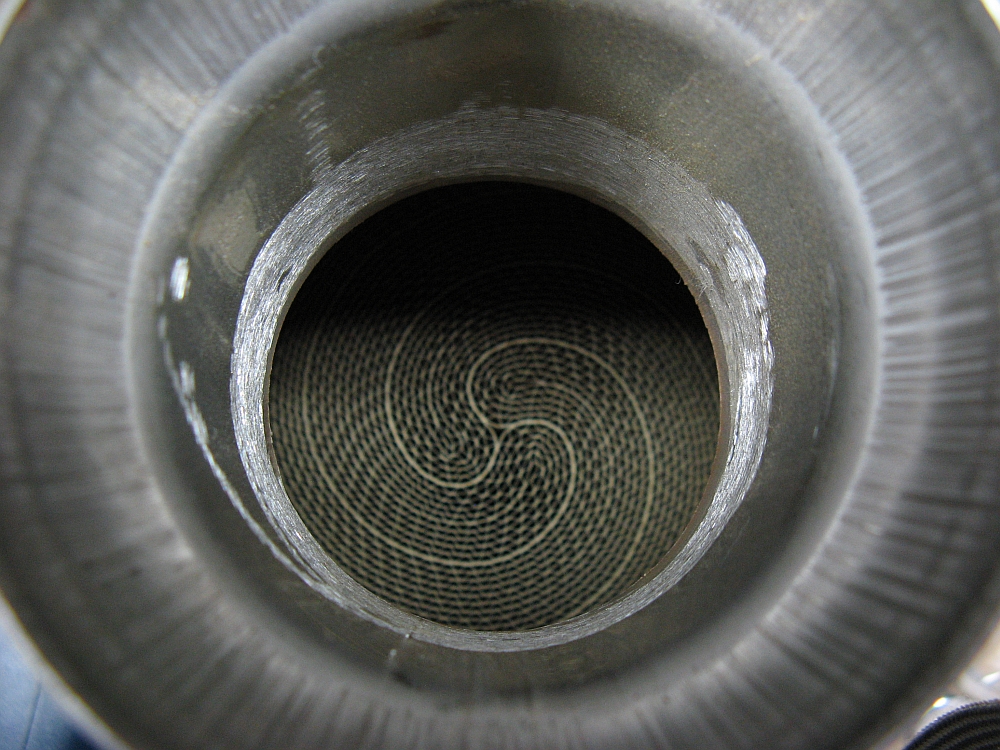
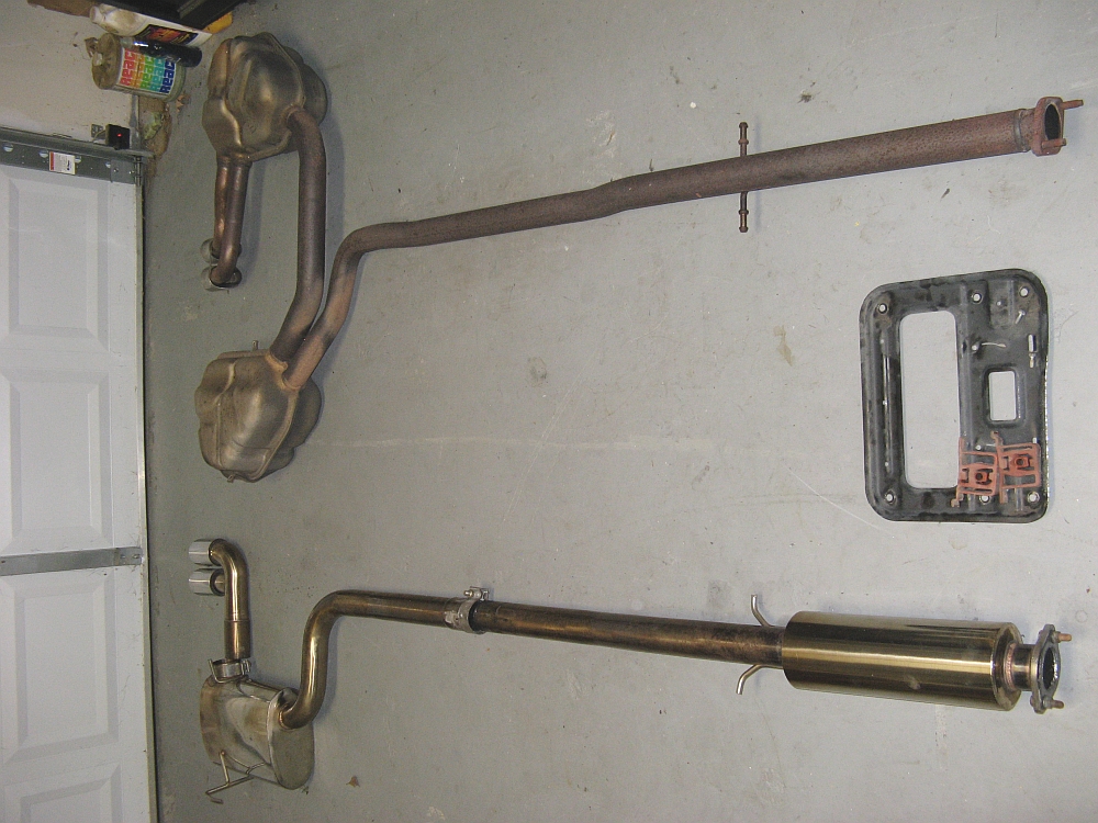
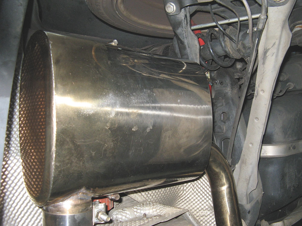
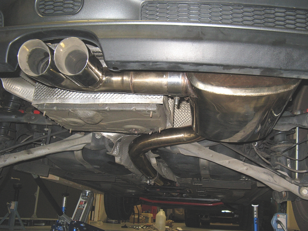
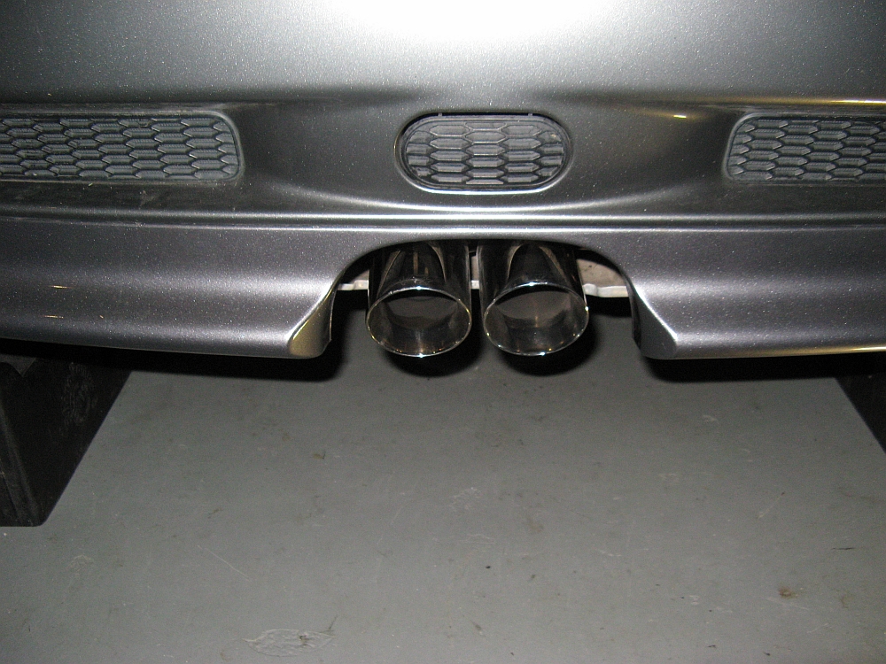
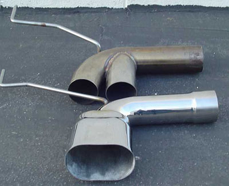
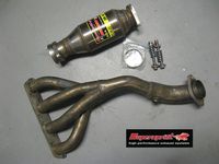
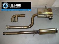
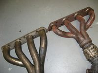
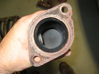
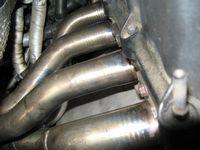
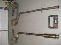
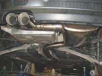
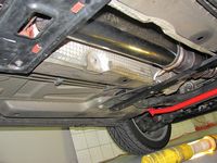
SuperSprint Header/Performance Metallic Cat and Ireland Engineering Exhaust installed.
Both of these items were found on different Mini forum classifieds- the header was used for a few weeks but the cat was new, the IE exhaust was used for a brief time and came with nicer Alta tips. Since they were installed at the same time I cannot speak to sound/power differences from OE for each one but with the header and exhaust both installed, both sound and power increased (or sound/feel like it). The header exhaust combo does not sound like it is connected to a 1.6L 4 cylinder motor at all but something larger- low aggressive tone and lots of amplified burbles and pops. I can't say that I notice a lot of drone either, I am very pleased with this setup. There is some discussion about this IE exhaust on NAM HERE.
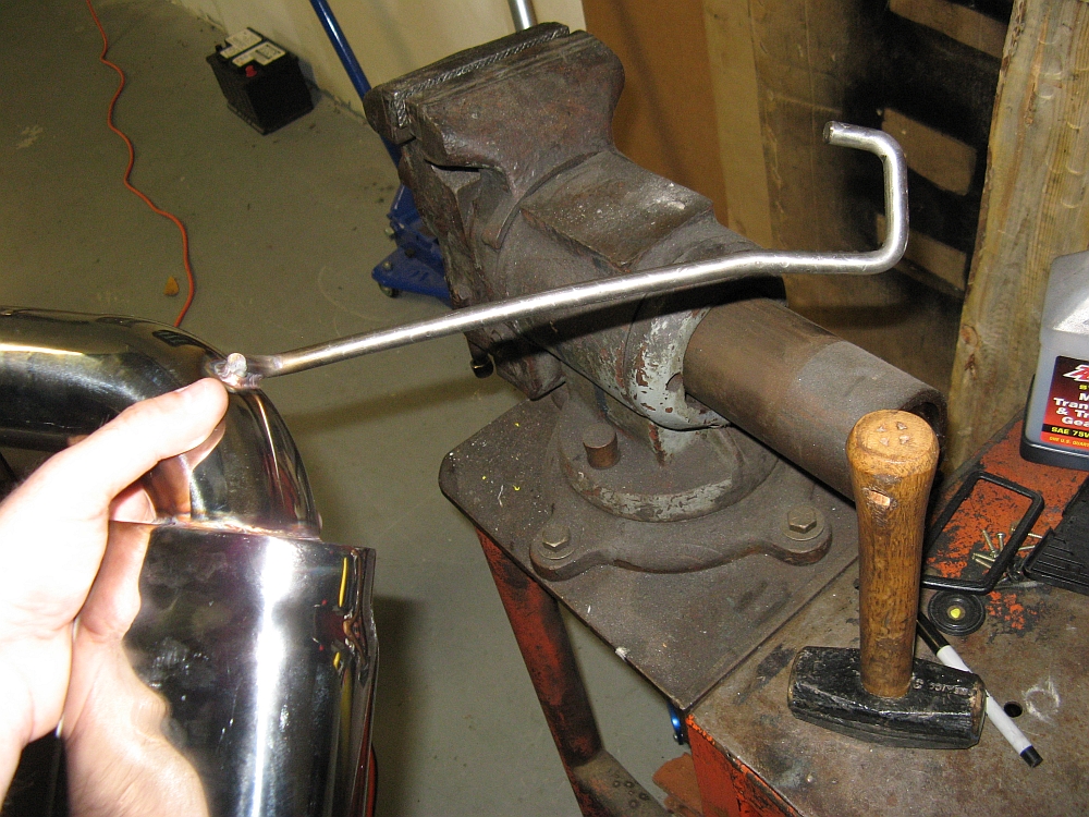
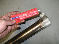
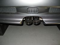
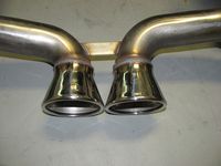
My header installation is detailed HERE, the exhaust was a simple R&R. The IE exhaust did take a bit of adjusting to fit but for the price has got to be one of the best values out there for this car. The construction is great, I prefer the passenger side/single muffler approach, it has to weigh half as much as OE, and the fitment issues were no big deal in the grand scheme. I did order the new "big mouth" single tip to see if I like it better than the Alta dual tips that came with it from the previous owner. Installing the IE "big mouth" tip required some grinding and bending to center and hang the tip....but I think it looks good. Hylomar EAP5 exhaust assembly paste was used on the slip joints to ensure a better seal.
TIS instructions can be found here for both: Exhaust System (Cat-Back) and Exhaust Manifold (Header).
SuperSprint Header Design For 02-06 MINI Cooper S video is HERE (Right Click > Save As).


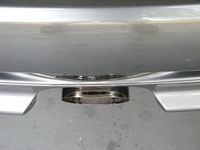
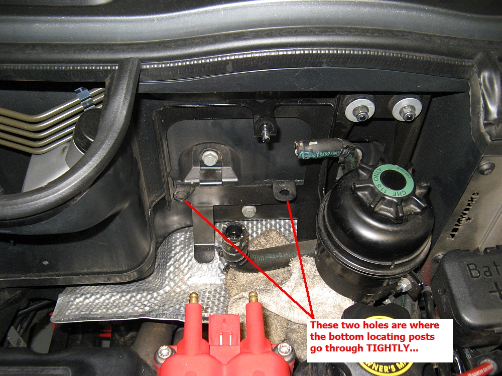
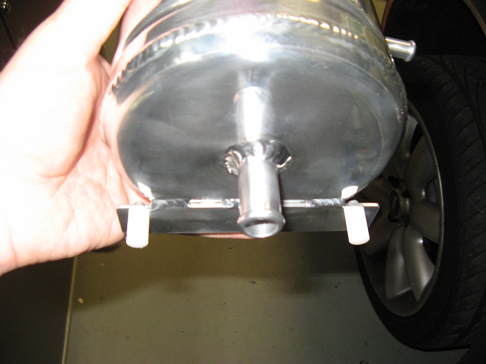
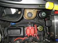
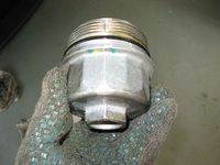
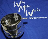
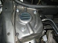
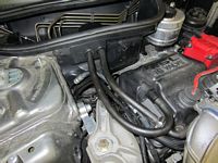
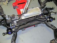
Forge Motorsport Aluminum Coolant Expansion Tank from Way Motor Works installed.
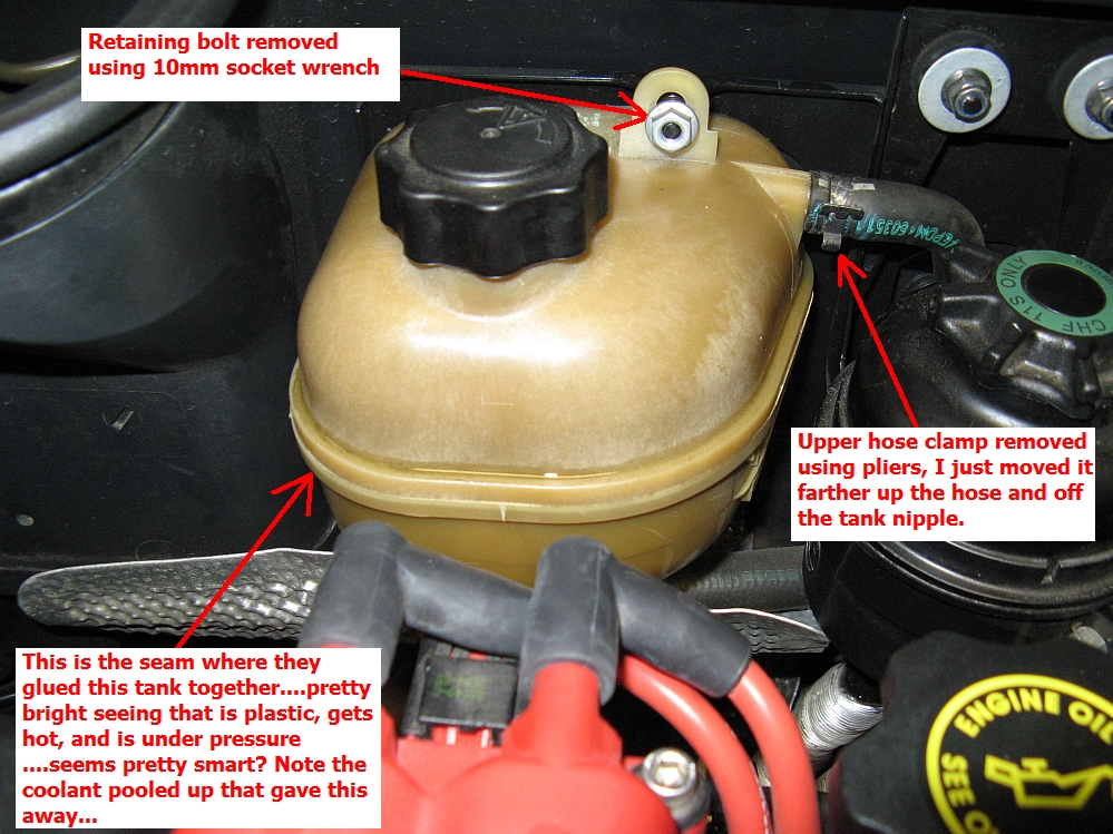
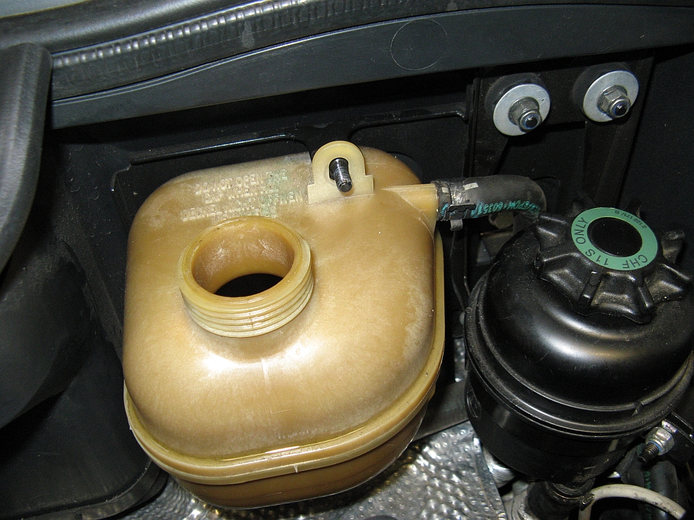
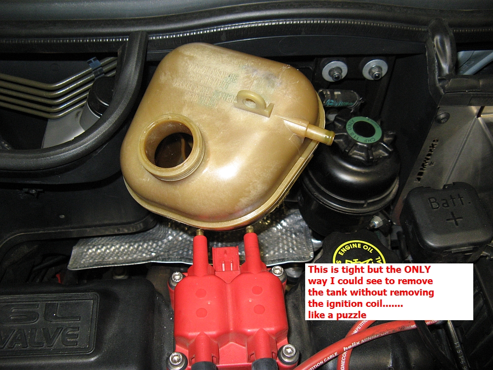
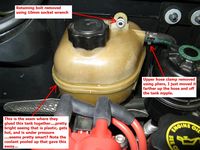
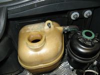
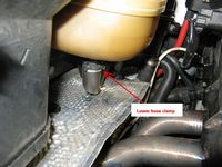
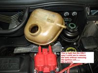
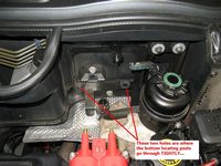
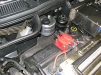
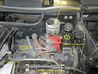
When I noticed water coming from the seam of our infamous Mini coolant tanks, I decided to replace it once with something better that would last instead of continuing to go through OE coolant tanks every few years. To start, I used my TopSider to drain all fluid from the tank and even a bit from the lower hose. The side/upper and lower hoses can be removed after pliers are used to slide the clamps off and farther out on the hose. Using a 10mm wrench to remove the single retaining bolt, the tank can be tilted forward and lifted out- note that the lower locating pins do not give up easily so PULL. The tank can be removed without removing the ignition coil, I did remove the rear ignition wires and plug though. The Forge tank installs the same way as the OE one just removed, you may want to cover the exposed ignition terminals with tape so that the tank does not get scratched while positioning it and connecting the hoses. After this is done reinstall the retaining bolt and relax- no worries now that the OE coolant tank might leak or explode at a less opportune time (REALLY, what was Mini thinking when they designed and redesigned this piece???).
Forge installation instructions are HERE.

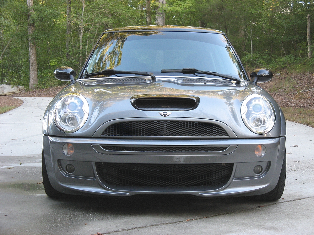
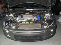
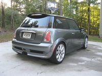
I had been thinking about buying a used/new aerokit or at a minimum painting all of the black trim. When perusing the forum classifieds I found that forum user Professor had a front aero bumper, aero grills, painted arches and skirts, and rear GP trim and wanted to trade for stock pieces plus the cost of the swap so I sent him a PM expressing interest. After sending some pics of my pieces to him and getting prices on the new pieces I needed and clips, we decided to do the swap. I left at 1AM to drive up to KY from GA (about a 900 mile round trip), after getting there the transplant for my car took a few hours and I was back home by 8PM (Longggg Day).
BIG THANKS to Aaron since he did 99.9% of the labor
The car already looks great, but after the upcoming springs and wheels installation should look a LOT better.......


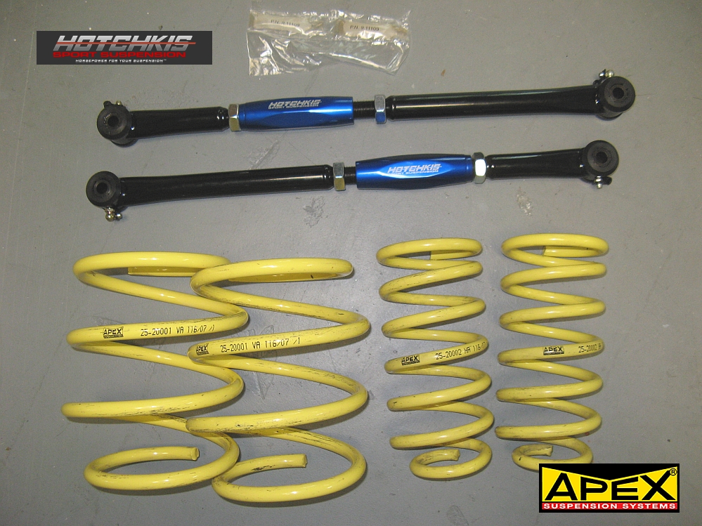
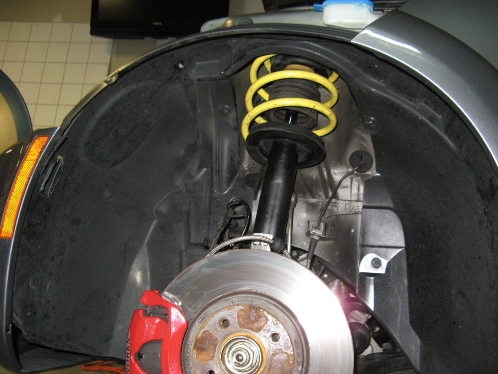
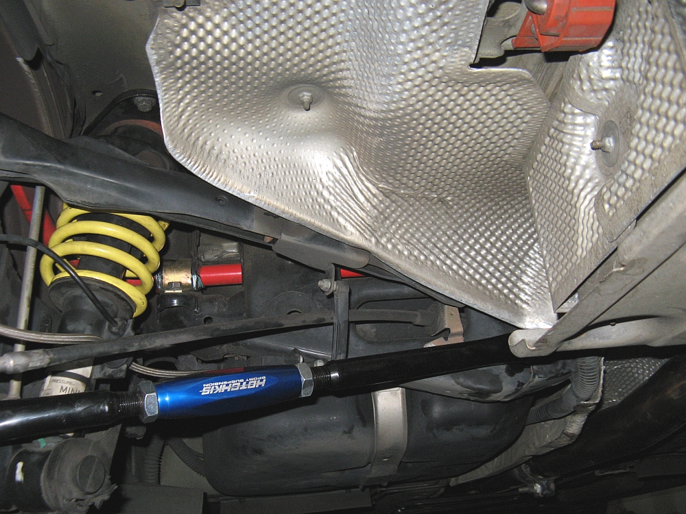
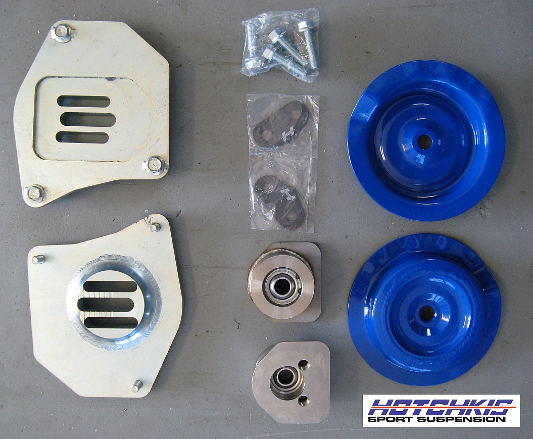
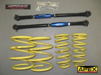
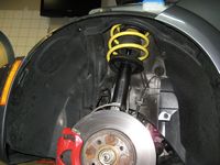
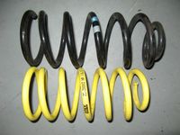
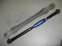
Apex Suspension Systems springs found in NAM classifieds and Hotchkis rear adjustable control arms from Way Motor Works installed.
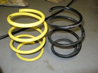
I had been looking at TSW springs as a stopgap until I get coilovers but I found these lightly used APEX springs CHEAP. I emailed APEX about spring rates and they are 28 N/mm (~160 lb/in) for the front and 36N/mm (~206 lb/in) for the rear, a little more than OE but not super stiff and most important are linear and not progressive. I don't think the front spring rate takes into account the progressive bump stop. They lower the car slightly more in the rear than in the front to reduce the factory rake and level the car- they are listed as 30mm drop all around. APEX is based in Holland and seems to have a quality spring at a value price, they can be sourced from Moss Mini.
The Hotchkis Control Arms are adjustable to bring the camber back to spec after lowering, and a bit stronger then OE as well. These are the important piece when lowering the car, the front does not change enough to warrant camber plates but the rear needs some help as the camber is increased noticeably.
The car now corners flatter but no perceived increase in ride harshness (they actually might be less harsh than OE and seem to be better matched to the OE damping rate).......I think the APEX springs are a winner and I'm not quite sure why there are not more threads about these springs on the forums.
My installation write-up for both springs and RCAs can be found HERE, Hotchkis RCA installation instructions are HERE.

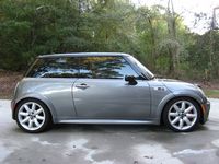


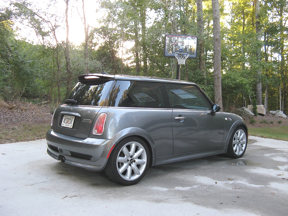
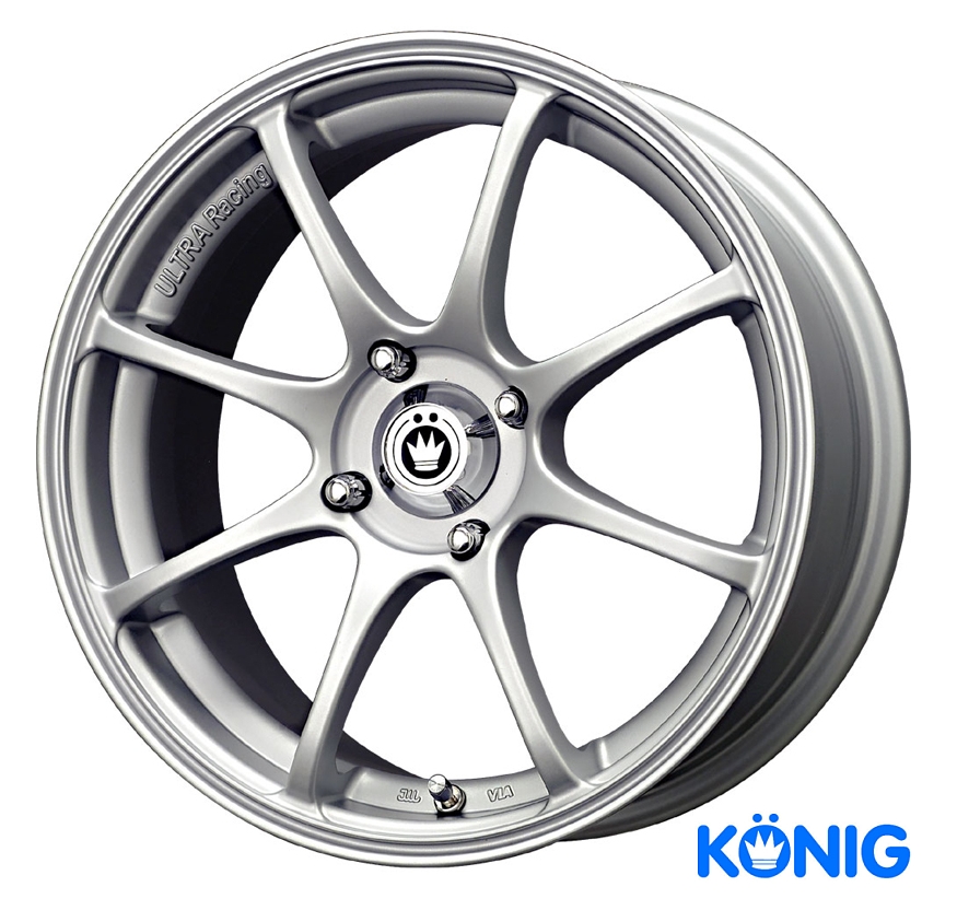
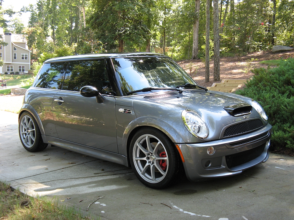
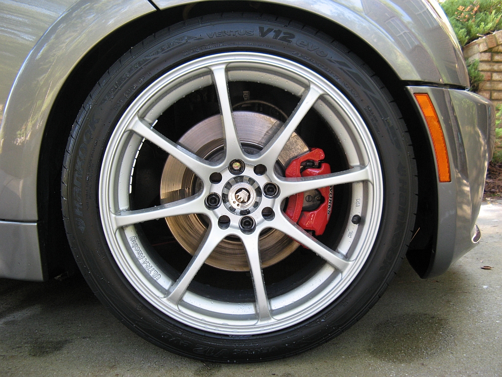
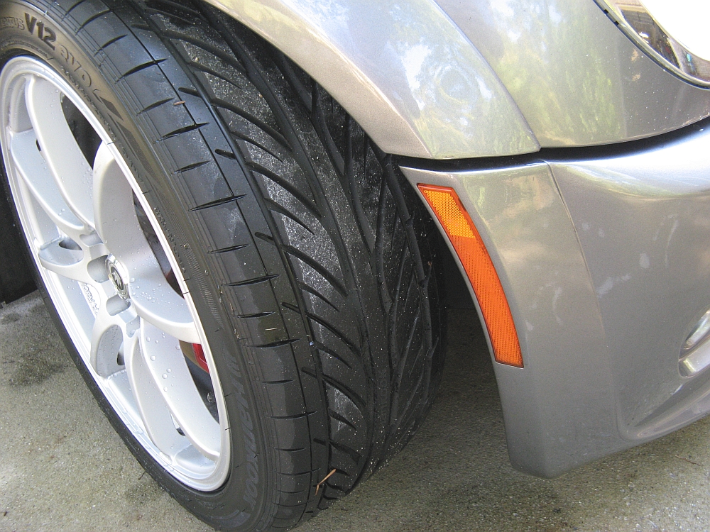
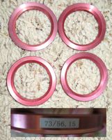
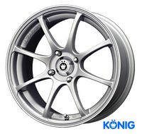
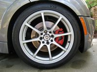
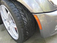
Konig Feather wheels and Hankook Ventus V12 Evo tires (215/45/17 size) from Kauffman Tire installed. The Konig wheels come with plastic hub-centric rings but I decided to not use/replace them with metal hub-centric rings from Discount Tire Direct. The plastic rings have been known to not do so well in aggressive driving (like melting). 73mm OD by 56.15 ID was the recommendation and they fit perfectly.
The Konig Feather wheels weigh 16.8 lbs to the ~25 lb weight of the OE oxymoronic "Superlight" wheels. I had originally ordered Dunlop Star Spec Direzza Z1 tires but they did not arrive in time so I had to go with my second, but cheaper, choice. I agree with the Car and Driver Review that the Hankook V12s do not provide a LOT of feedback but they are deceptively sticky.
MotorTrend has an article on Hankook and the V12 HERE.
Auto Bild Sportscars article on the 215/45R17 (same size I bought) is HERE
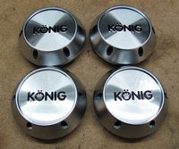
[EDIT] If you get tired of the center caps that came with the Feathers, the Helium center caps fit and are available from Goodwin Racing, I think they look better:
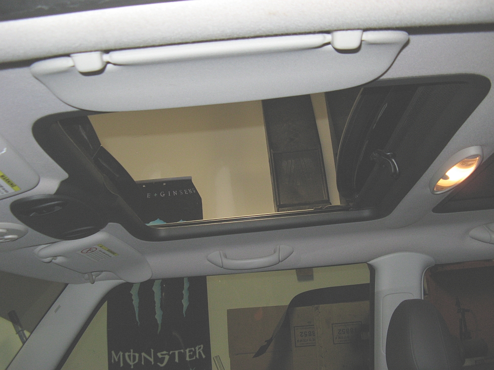
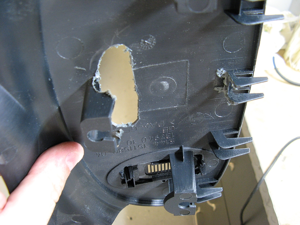
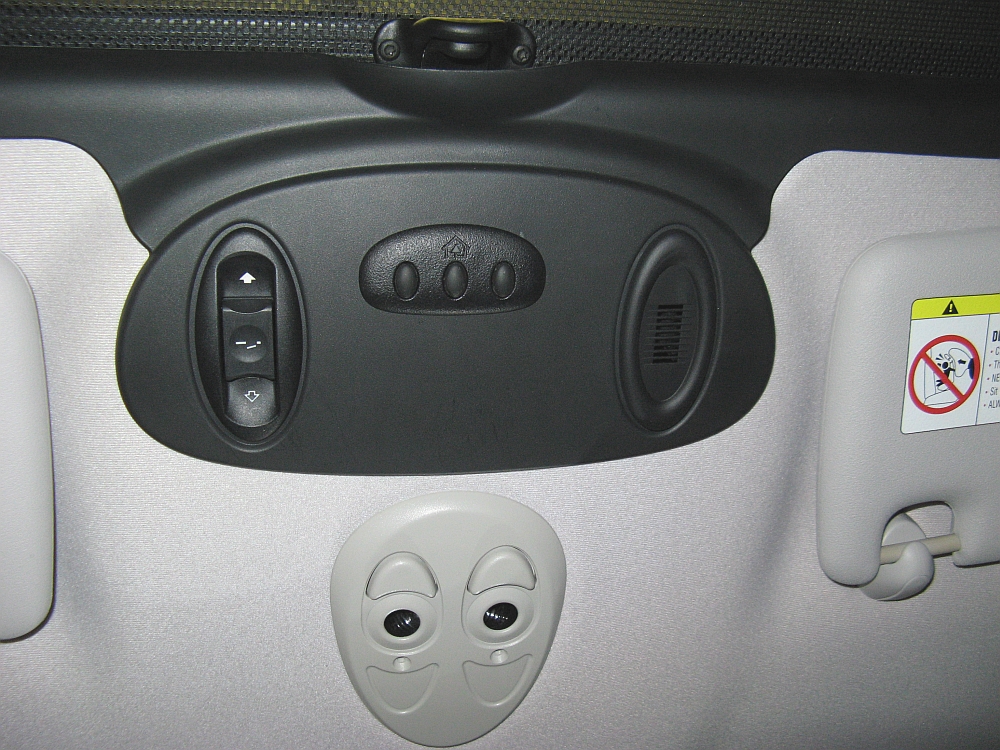
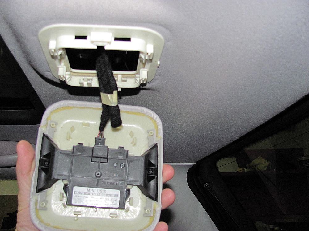
Homelink installed, purchased a rolling code model from eBay. I used the DIY guide HERE that another Mini owner assembled, but did some things differently. I didn't try to rewrite the DIY so the below is supplemental to the guide linked.
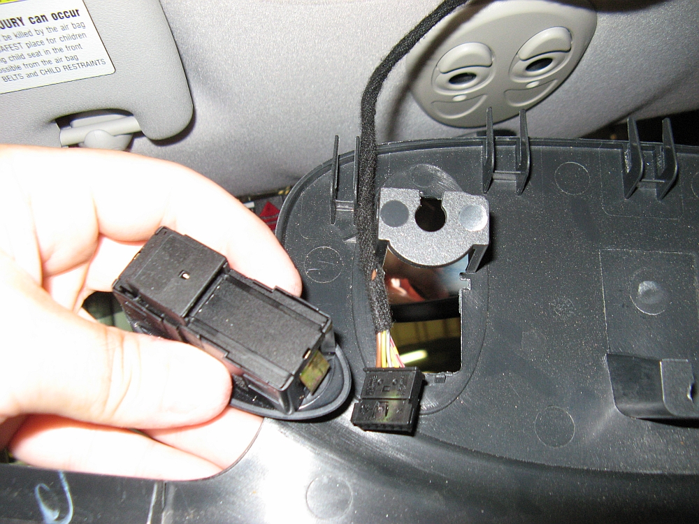
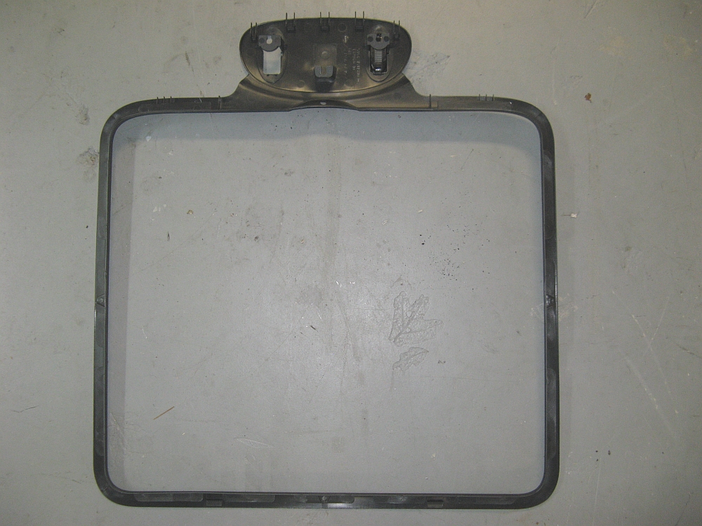
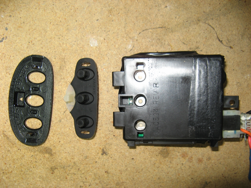
The sunroof trim was removed by pulling the rearmost section out and down and then the sides, followed by the front- you can see in the pics the way the front slides on to plastic clips. Unplug the sunroof switch connector (easier when removed) and the piece is free to modify. I did not disassemble the Homelink unit other than to remove the faceplate for installation. I used a Dremel tool with a carbide cutting bit to notch and cut the trim, overkill for plastic but worked well to remove the plastic to allow room for the Homelink module. Before cutting the hole, I test fit the Homelink in place upside down so I could make pencil marks to see where the buttons and the mounting tabs for the faceplate needed to be and cut a smaller hole than was required- it's always easy to make a small hole bigger, but the inverse does not work that well
Removing all tabs from the Homelink module allows it to fit a little better without interference. Not pictured, I also eliminated the plug/receptacle and soldered the power wires to the circuit board so that the front would have room to slide over the headliner. The Homelink module was epoxied to the plastic trim piece and due to the thickness of the plastic I found some small rubber pieces (little less than 1/8" thick) to glue to the ends of the rubber button plungers so that they would be tight once installed and work the same.I tapped the power wires into the existing radar detector wiring I had run up from the fusebox. Finally, the trim piece was reinstalled as it was removed, sliding the front in place first and then snapping the sides in place and finally the rear.
It seemed that my Genie garage door opener only liked ONE Homelink at a time, when adding this car my other car would not work, and vice versa (I don't have this problem with the Liftmaster opener upstairs, and the Genie had all openers cleared/reset so the max was not an issue). So, as a temp solution I dug out my old Liftmaster 635LM rolling code receiver and wired it in to the Genie opener, this is the receiver used for the Mini Homelink which allows the Genie receiver to continue working with the BMW.
Homelink programming instructions HERE, remember to program the remote to your Homelink FIRST, and then add the Homelink to your opener.


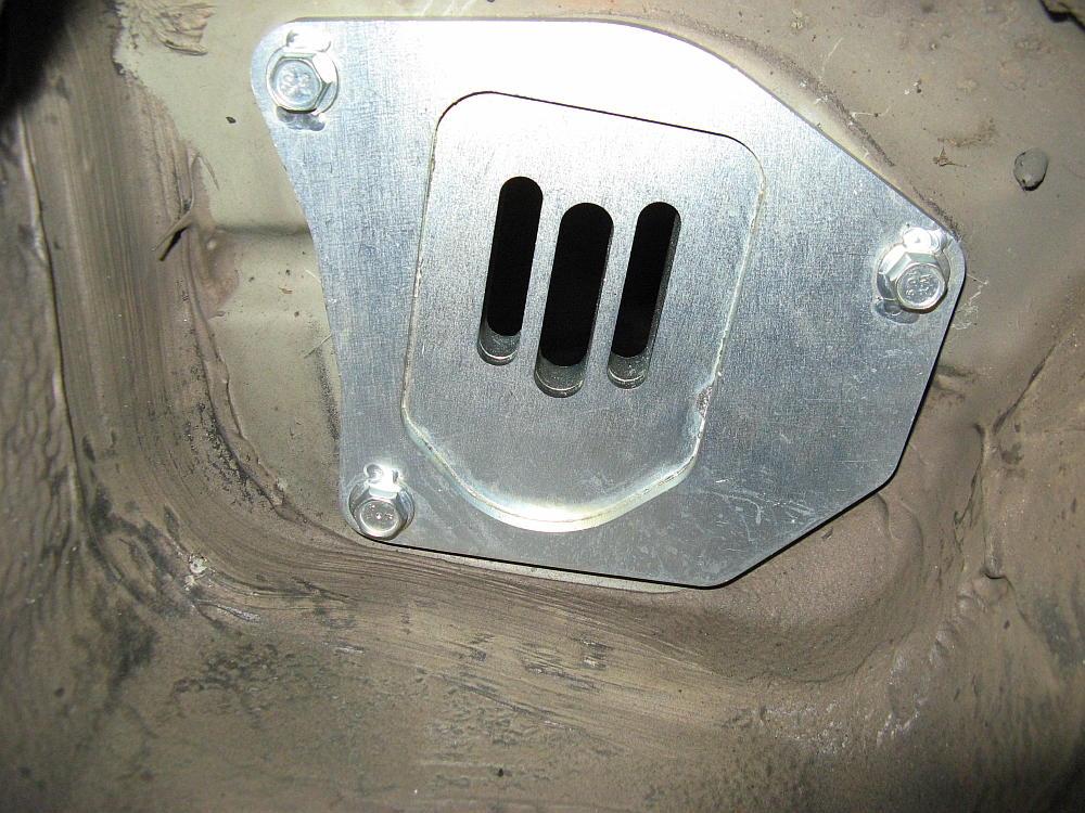
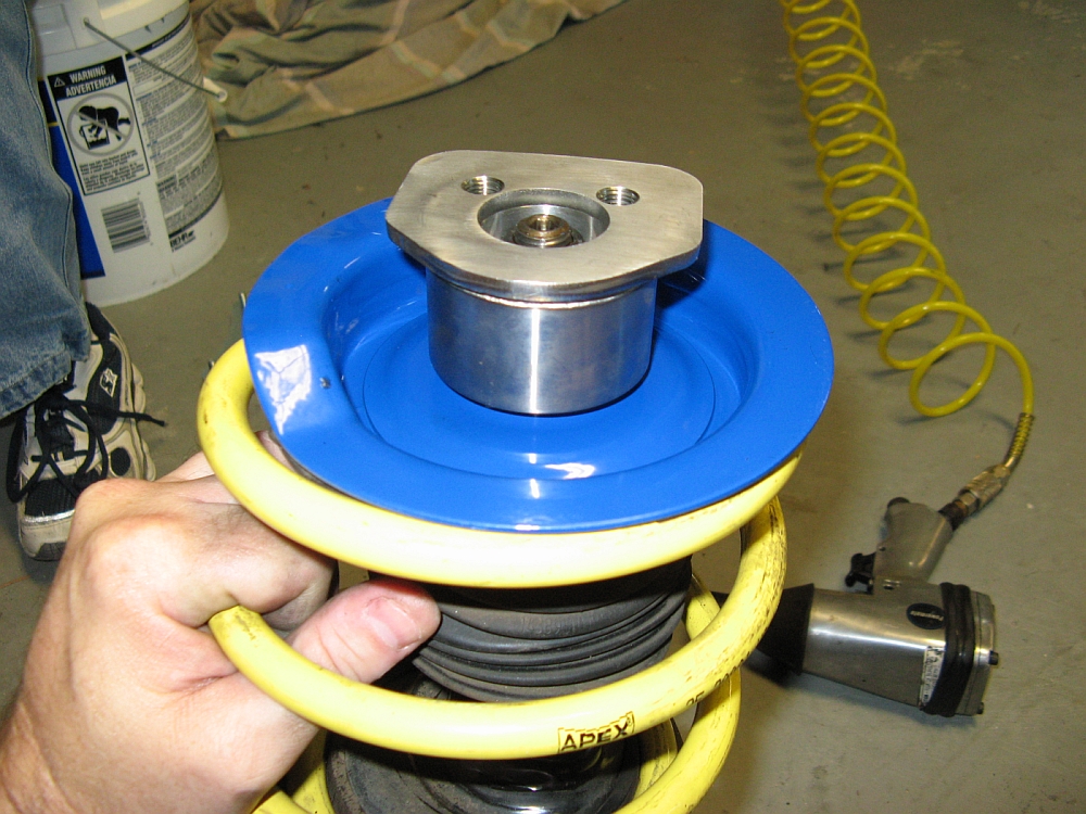
Hotchkis camber plates (P/N 30830 for OE type springs) from Way Motor Works installed.
I wanted to be able to dial in more negative camber AND reinforce the weak strut towers- these camber plates were the answer for both and allow for me to change hardware to accomodate coilovers at some point in the future. I did have some slight mushrooming, easily corrected with a small piece of 2x4 and a 5-lb hammer.
My installation write-up for the camber plates can be found HERE, Hotchkis Camber Plate installation instructions are HERE.UPDATE: Hotchkis no longer makes Mini camber plates but I was able to get the part number for the wear component, the bearing- Aurora Bearing P/N COM-M14T (PDF HERE.

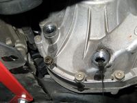
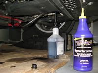
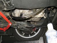
After trying Royal Purple Synchromax in my BMWs and being amazed at the difference it made in shift quality, I decided to try this in the Mini even though I had the BMW OE MTF-LT-2.
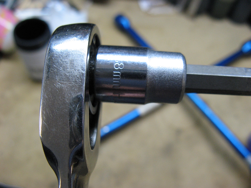
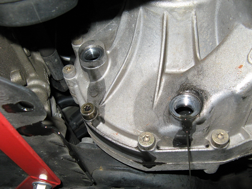
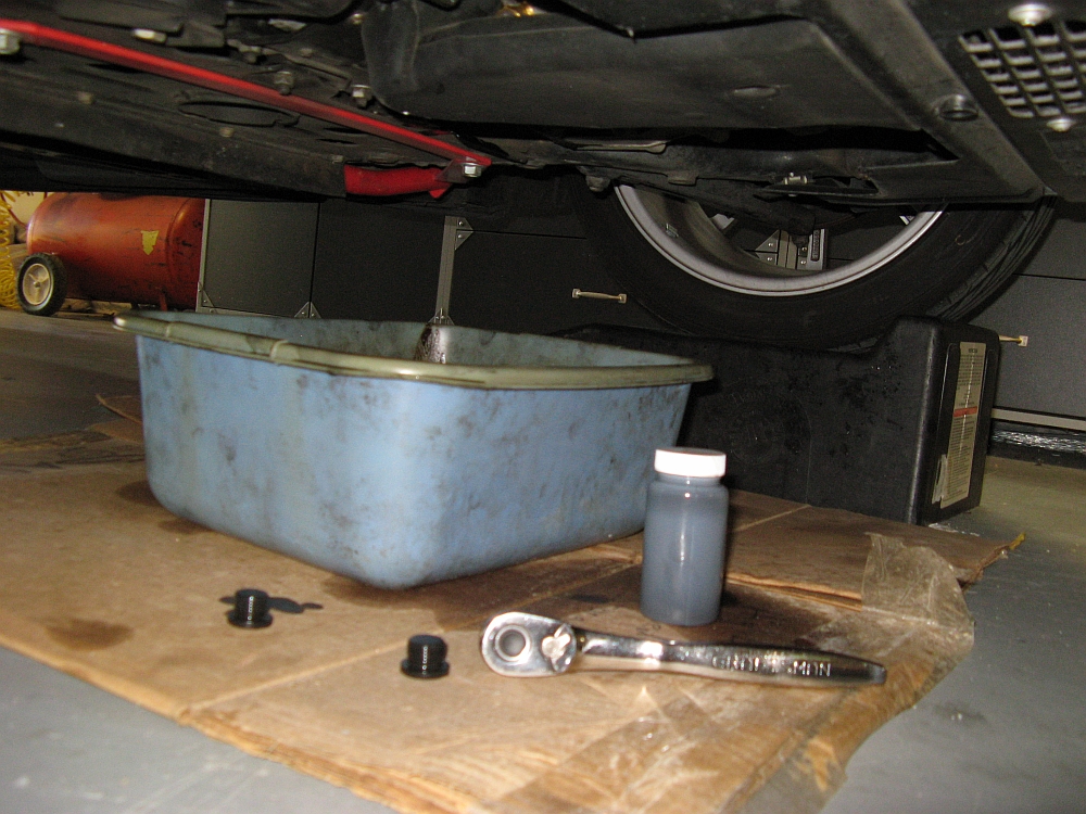
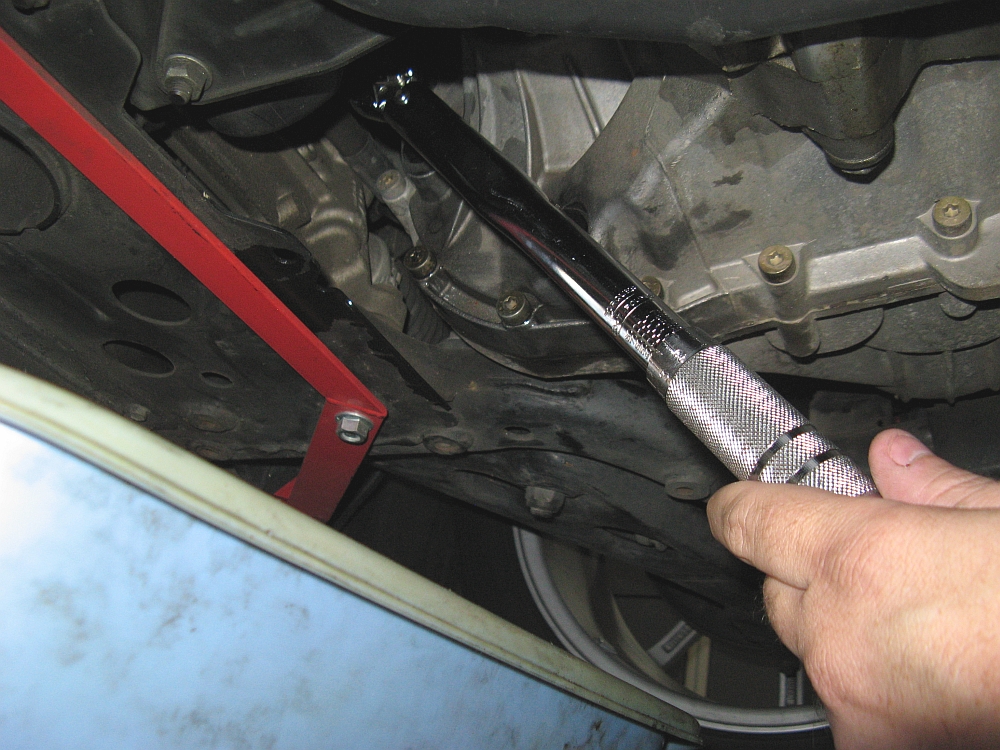
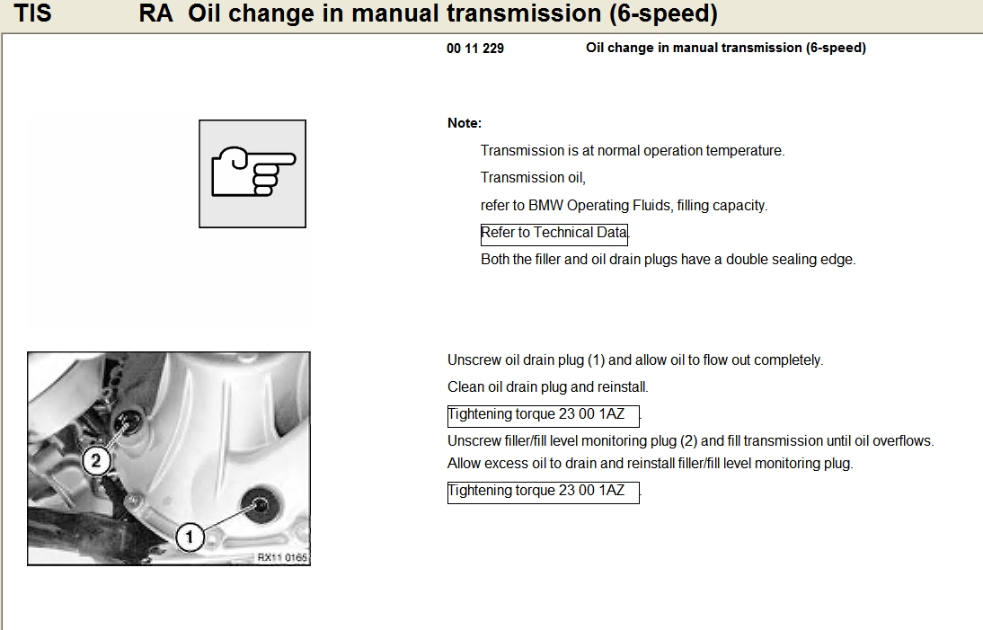
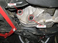
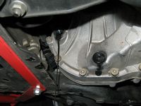
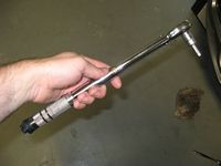
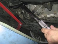
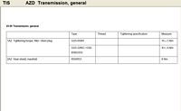
Cliffs Notes DIY: Raise car so that it is level front to back and side to side (I used ramps and two jacks at rear jack points), remove fill bolt first (8mm hex socket), then remove drain bolt and drain all old fluid, reinstall drain bolt (43 Nm or ~32 ft/lbs), fill through fill hole using tubing and/or pump until fluid starts to come out, reinstall fill bolt (43 Nm or ~32 ft/lbs)- ENJOY
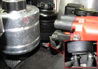
I used a hand pump to fill the transmission-a little less than 2 quarts. The car should be at operating temperature when you do the change, this affects the oil level since heat=expansion and it also helps in draining all the old fluid with the particulate suspended:


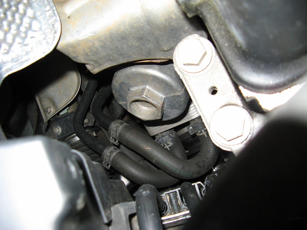
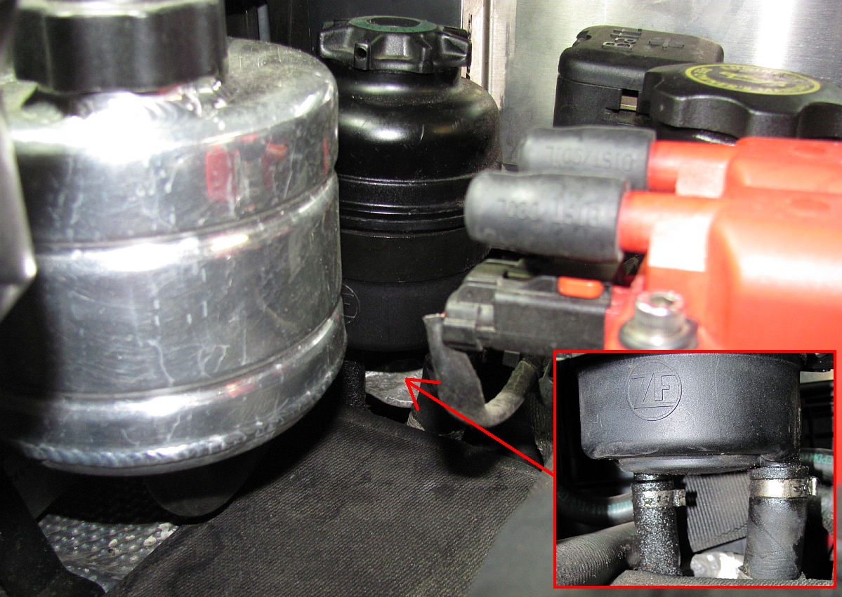
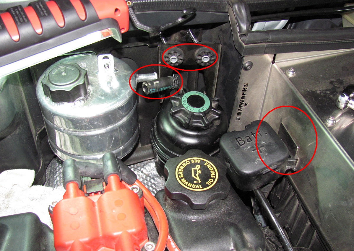
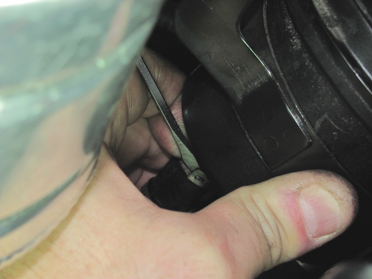
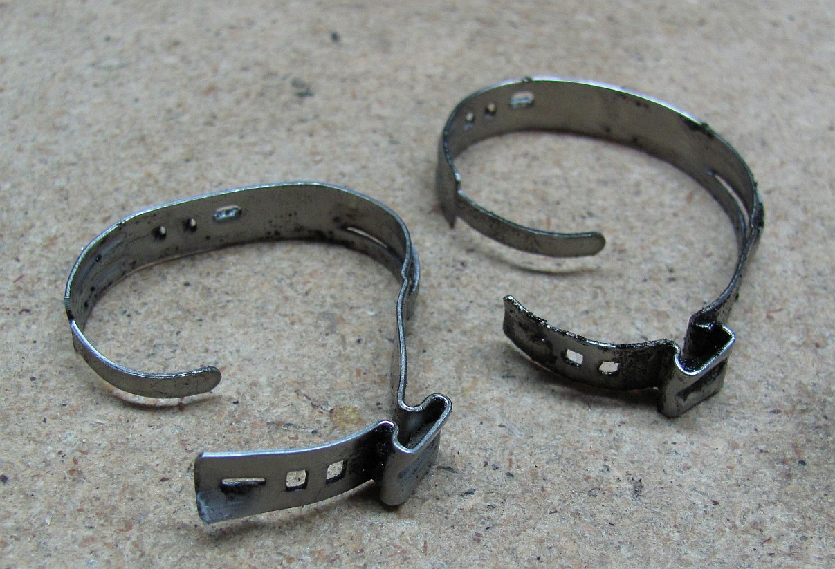
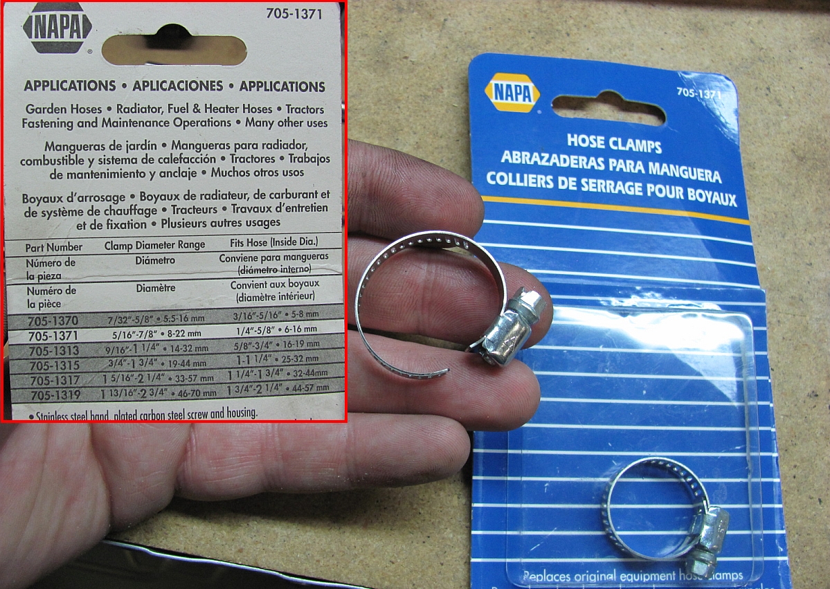
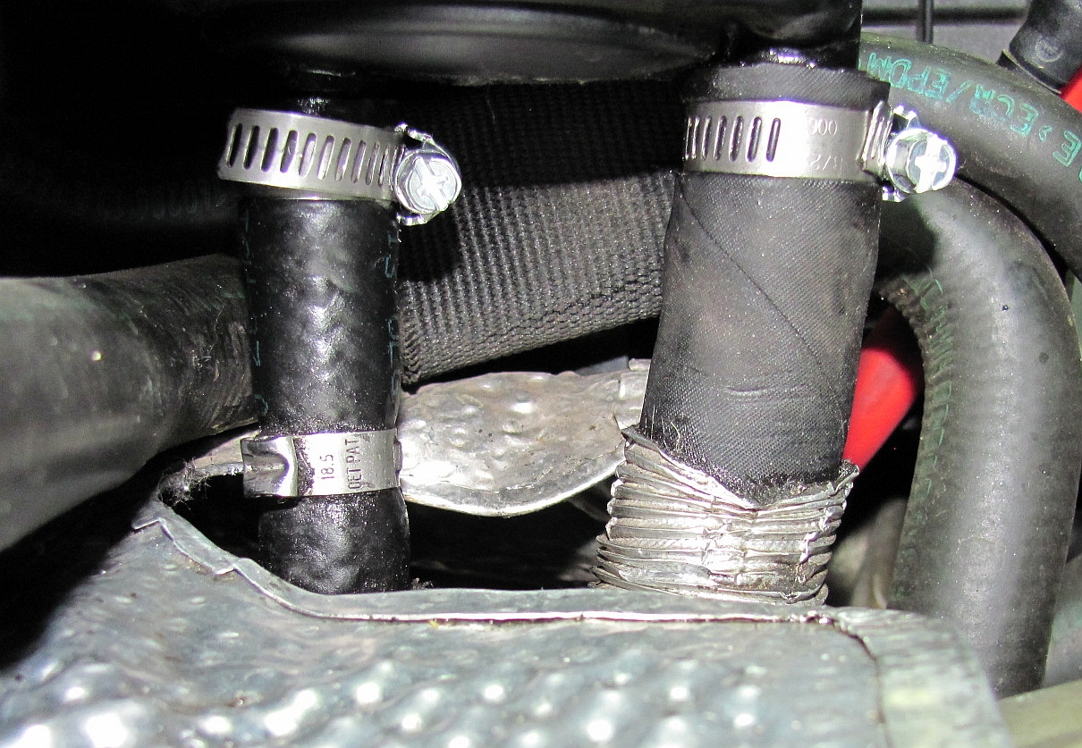
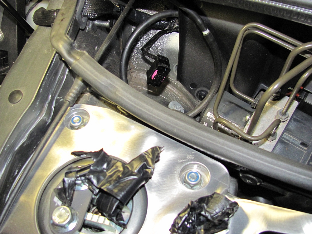
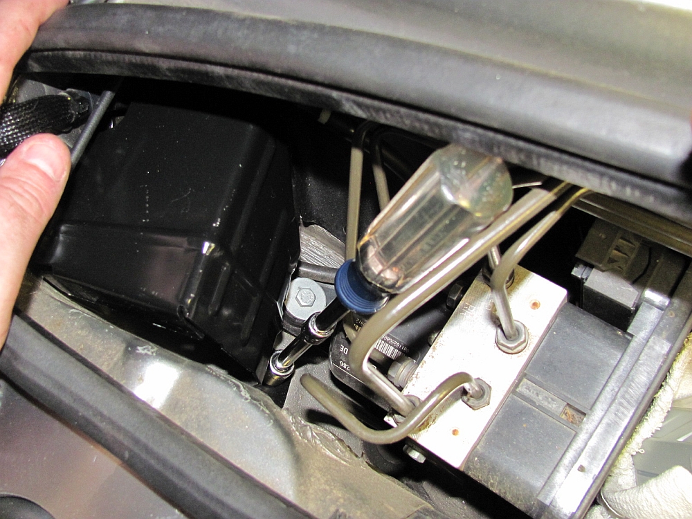
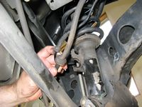
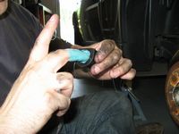
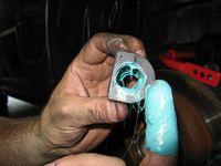
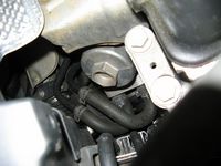
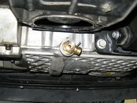
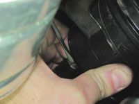
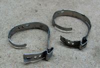
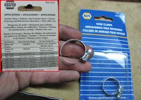
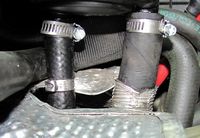
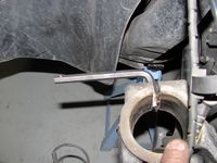
I noticed that I had a small puddle under the Mini and traced it back to a leak above the power steering pump- kind of hard to spot, just a small amount on the bracket. I figured it might be the OE press fit hose clamps and it looks like that is the issue. Removed the two bolts holding the reservoir bracket to the car, the hose from the coolant tank, and the battery terminals box from the airbox- this allows enough room to work. The old clamps were pried apart with a small screwdriver and the new hose clamps were undone all the way so that they could be slipped over/around the hose without removing them, and then tightened in place.

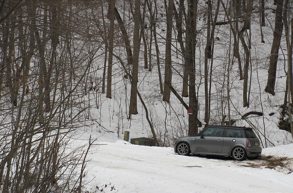
The week of 1/9/2011 brought us 6-7 inches of snow east of Atlanta and those in the north GA mountains 12 inches (as reported by a friend in Blairsville). We went to the mountains looking at cabins the following weekend and found the roads to be quite good, actually less ice than we still had on the roads further south- just have to watch the loose gravel they put down on the road for traction on the ice, it can be almost as treacherous. The MCS with summer tires was pretty fun on HWY 60, keeping in mind that the fun has to be dialed back to accomodate the reduced grip
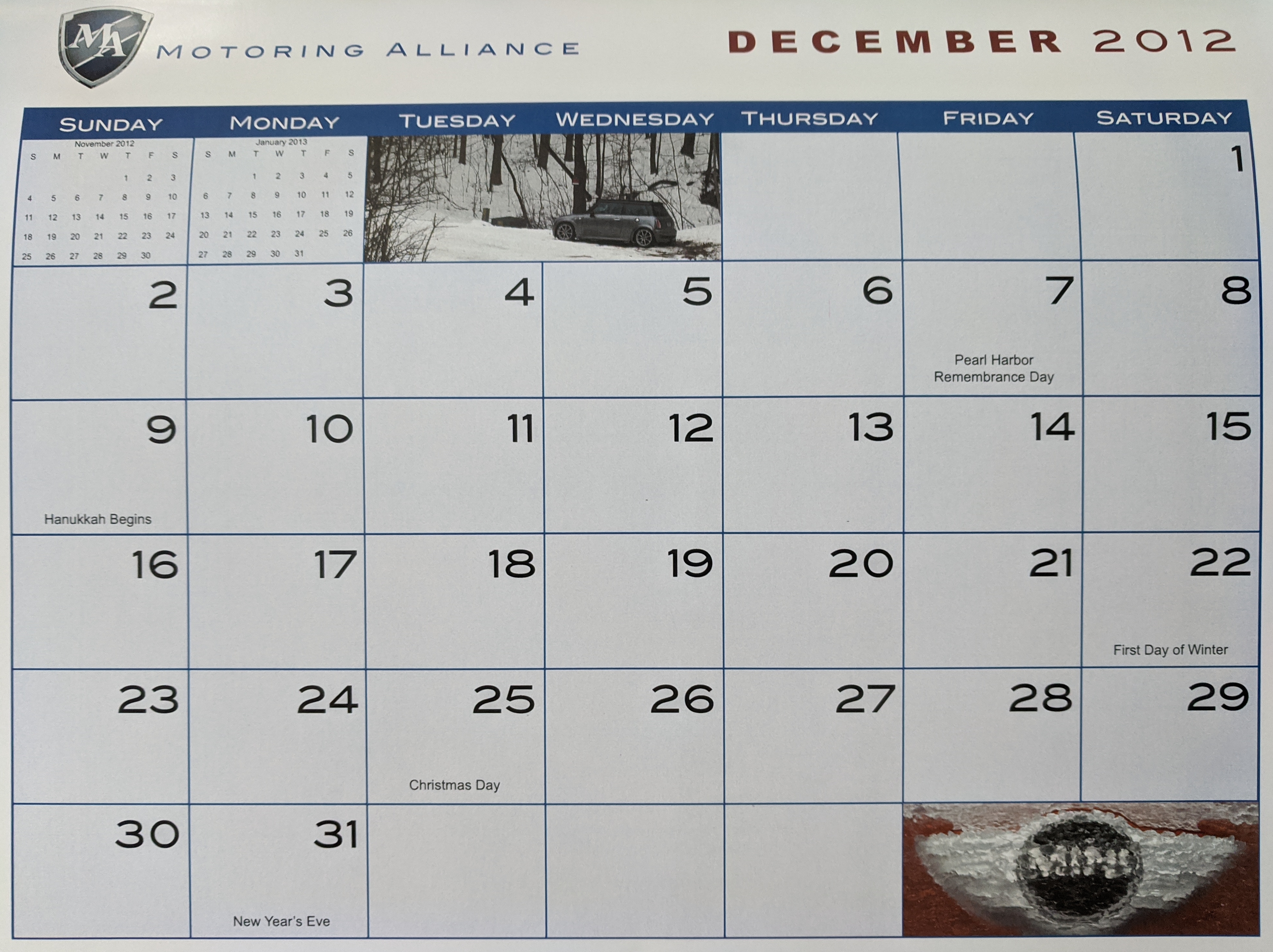
One of these pics was also selected for the month of December in the 2012 Motoring Alliance Calendar


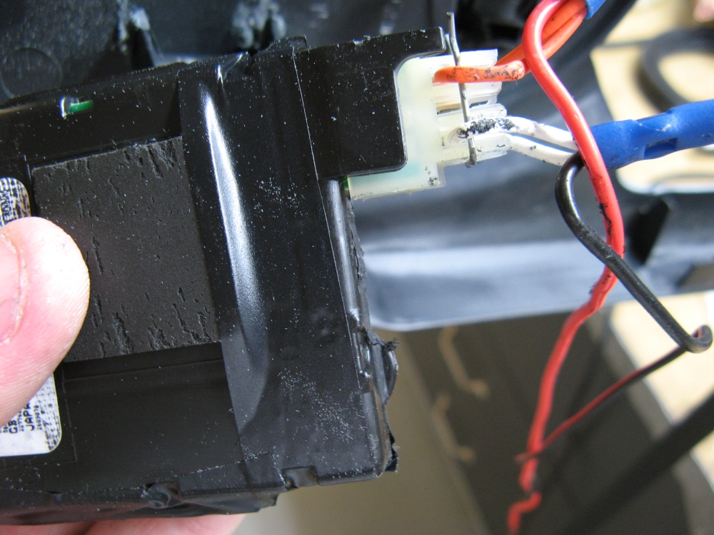
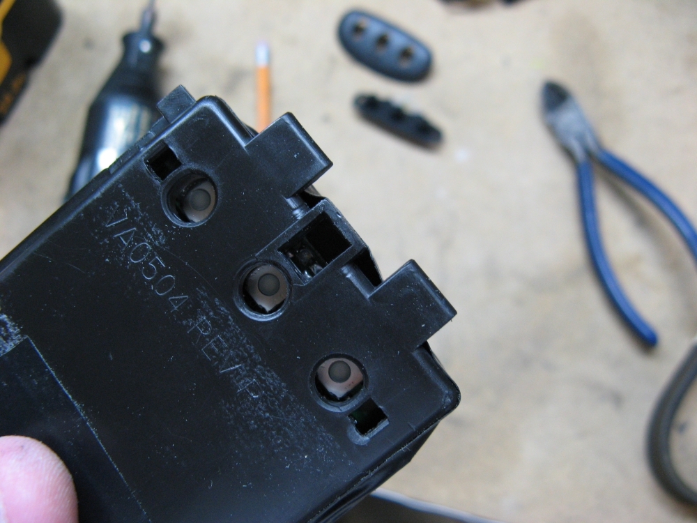
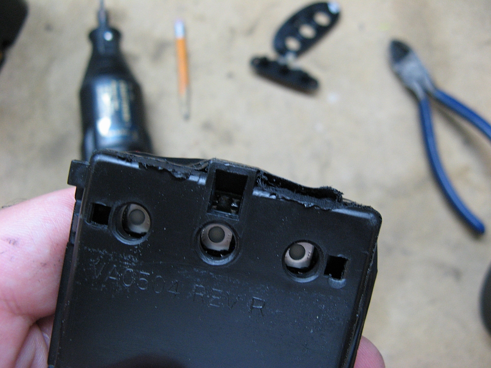
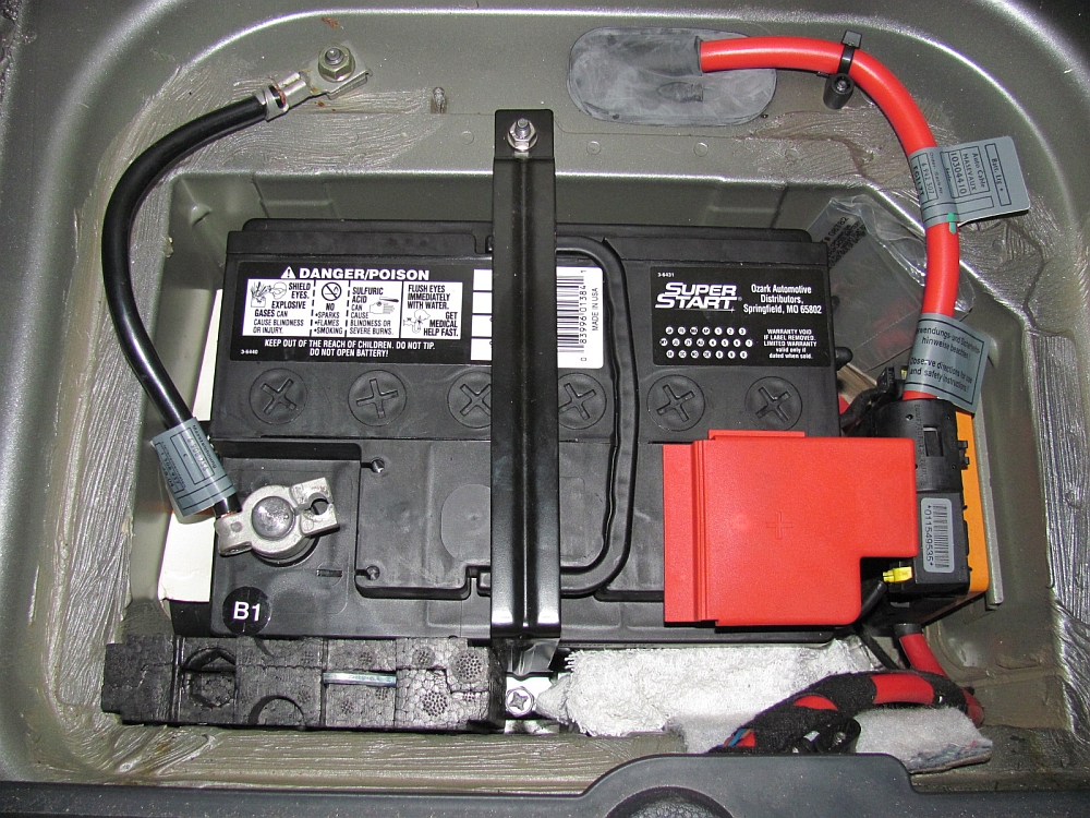
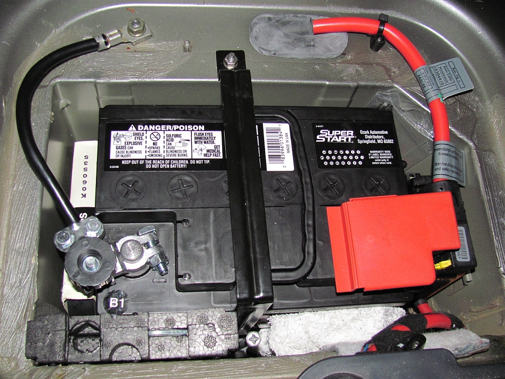
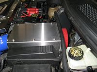
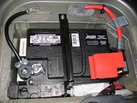
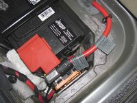
The battery in the Mini went to battery heaven, would not charge past 65% so I went ahead and replaced it as a preventative measure. The only battery that I could find that was a direct fit was at Oreilly Auto Parts (P/N 47-72OE), archived listing HERE, same specs as standard fit P/N 47-72. By direct fit I mean the battery is held in place by the base mount securely AND the factory vent tube plugs right in as it did on the factory battery, in picture this is located on the right/US passenger side of the battery.
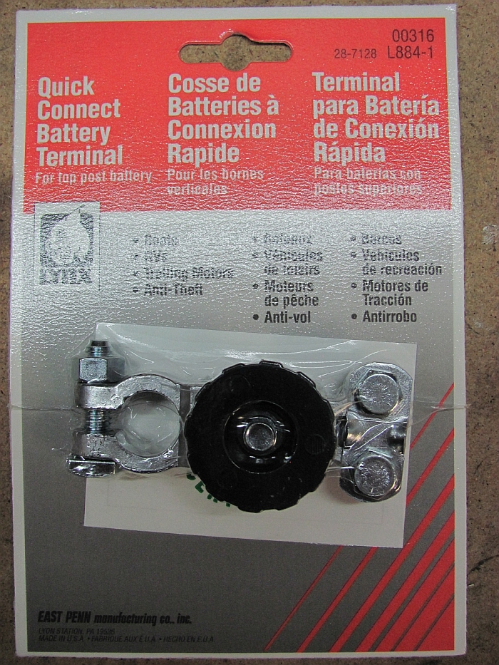
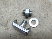
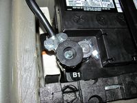
To add to the adventure, in removing the old Duralast battery the ground post bolt snapped. This was in the parking lot of the parts store so I drove it home with the ground post pushed into place. Oh well, this was an excuse to install a quick disconnect for times when the battery needs to be disconnected. Cut old terminal off and stripped wires to install the quick-disconnect lug once I made it home.
You can also see in the pics where I have my spare accessory belt stashed to the left, I also carry the belt tensioner tool in the back for a quick replacement.

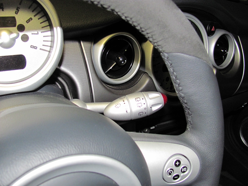
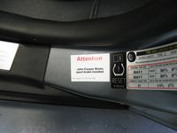
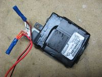
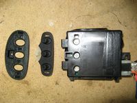
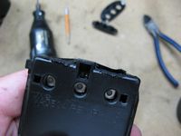
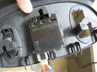
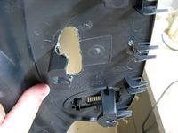
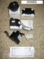
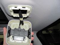
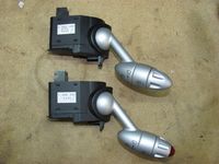
OE Alarm Retrofit Kit for my 12/04 build date 2005 MCS (P/N 65730403439) from Classic Mini installed. Jayson is the NAM contact at Classic for discounted parts, phone 440-585-9950 or email bmwparts@driveclassic.com - ask for the North American Motoring forum discount (~20%). The kit includes the alarm siren with integrated tilt sensor and bracket, the interior motion sensor, and the new wiper stalk with alarm indicator. The alarm installation is fairly easy and can be done in less than an hour, but will need to be activated by the dealer or your independent mechanic- usual charge is ~1 hour labor. Way (WayMotorWorks) activated my alarm, turned on the rear fog, and reset the oil service indicator to be 7k miles instead of the OE 15k miles for $50.
Old Mini OEM Alarm Installation Instructions HERE (only difference is that the tilt sensor has since been combined with siren to eliminate a step)
Mini Alarm Owners Manual can be found HERE
My DIY Installation guide is HERE


Way (WayMotorWorks) installed his quick tune while I was at his shop for the alarm activation. The Mini seems to have more linear throttle response and overall is smoother with this tune, some comments can be found HERE. Way emphasizes this is more of a driveability tune than a max power tune, but the $225 paid for the quick tune can be applied towards his dyno tune- GREAT Deal

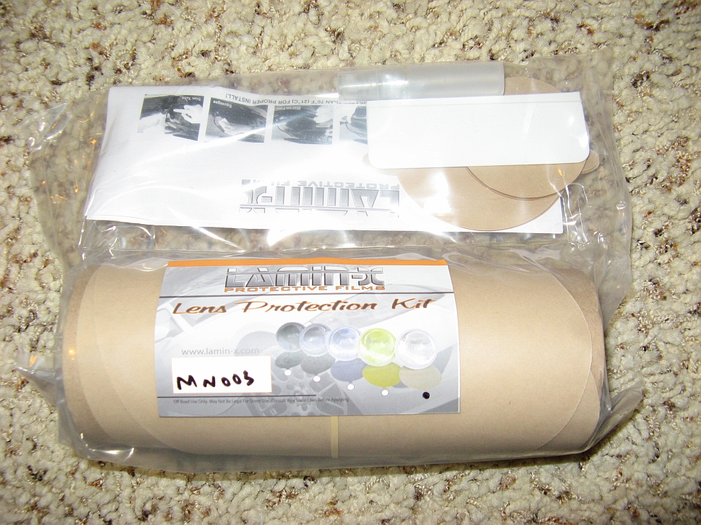
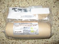
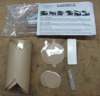
20 mil Headlight/Parking light film (with cutouts for washers) and 40 mil fog light film (P/N MN003) from Lamin-X Protective Films finally installed- I ordered almost a year ago and finally got motivated to install it
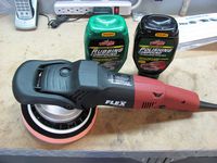
I also polished the headlights first using rubbing compound and then polishing compound with a Flex buffer. For super bad pits you can use wet sand paper, some time ago I used 1500/2000 followed by buffer polishing.
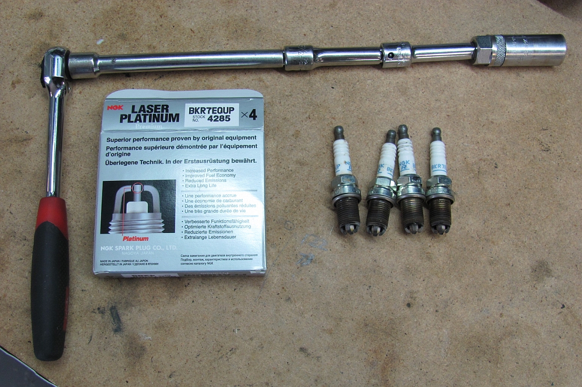
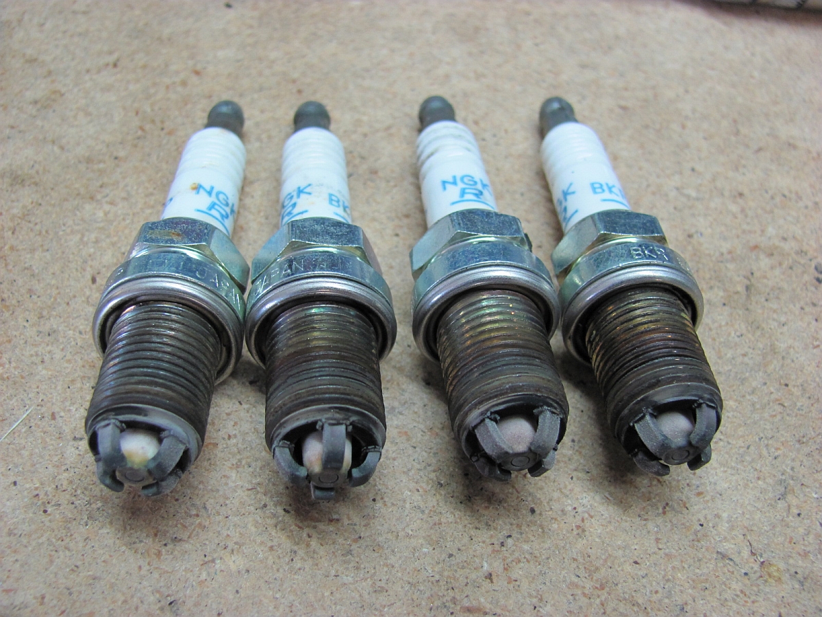
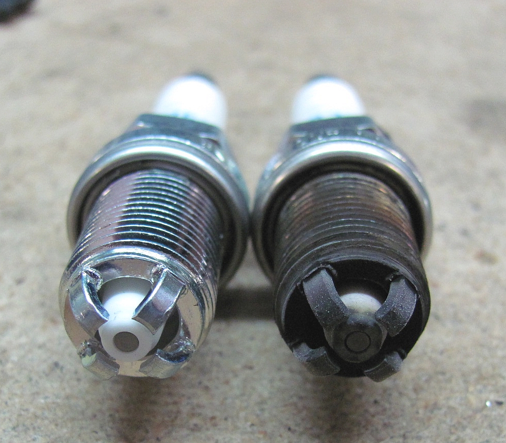
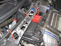
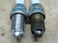
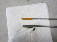
I had noticed the idle was rougher at times and in my quest for answers found that Mini recommends JCW owners replace their "NGK BKR7EQUP plugs at each subsequent service and maintenance interval" according to the MCS JCW Installation instructions. Mine had been installed for ~30k miles. I was able to source the NGK BKR7EQUP cheapest at Amazon, no need to pay the dealer markup at twice the price for the JCW label.
A good spark plug guide/write-up on NAM can be found HERE.
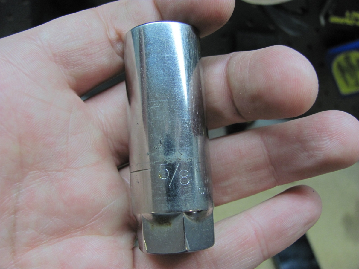
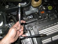
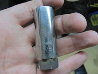
I started by removing the front two spark plug wires from the coil and then removed all wire plugs from the valve cover. To remove the spark plugs you will need a socket wrench, extension(s), and a 16mm spark plug socket (5/8" will work too). When reinstalling the plugs, the torque spec is 20 ft/lbs. I also cleaned up the coil terminals a bit with some mild scotch-brite.
After installing the new plugs I can tell a difference in idle and driving, I think I will start replacing these every 25k miles.


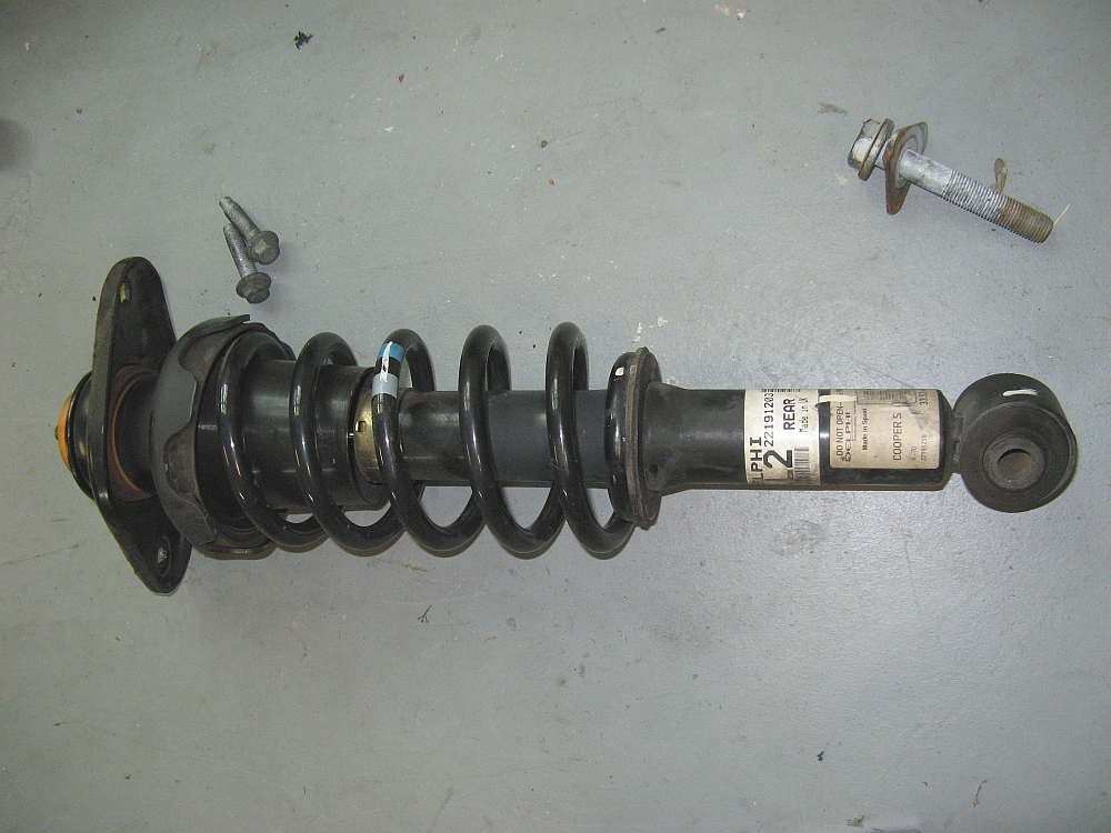
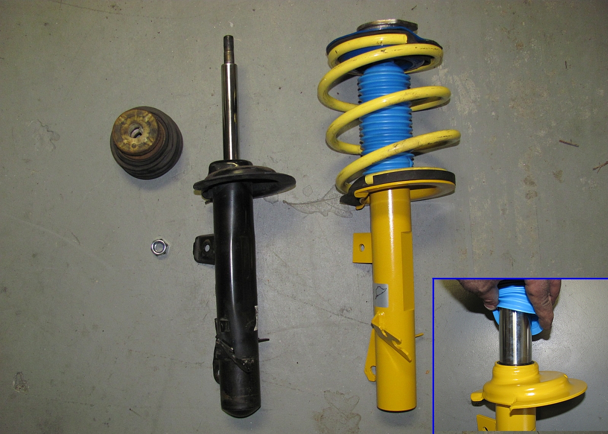
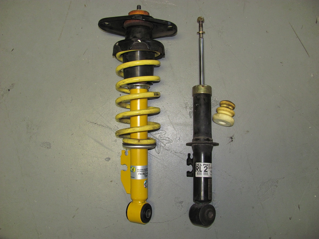
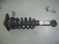
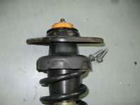
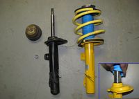
At 140k miles and 6 years, I figured the OE dampers had exceeded their lifespan. I decided on Bilstein Sport dampers to pair with my Apex springs, I sourced them from Turner Motorsports on sale and saved ~$100 off their already reasonable price, GREAT timing. The Bilstein Sports are made specifically for lowered cars and actually make up some of the travel lost lowering on OE dampers with lower spring perches.
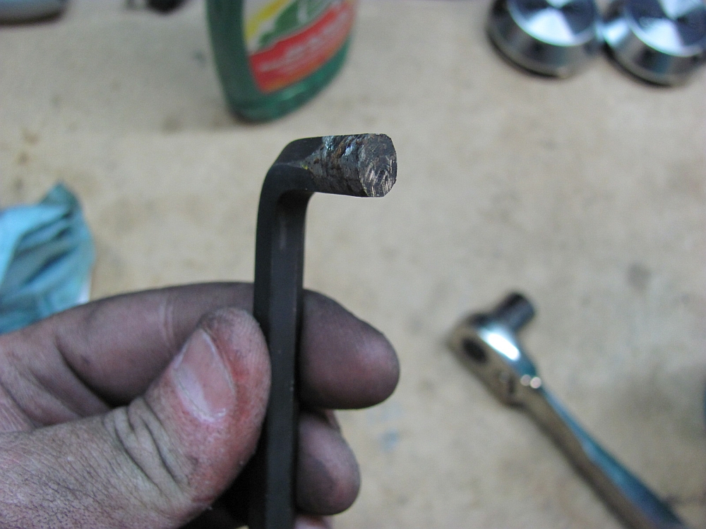
I had read Keith's review of installing these HERE. Thankfully I did not have similar issues although I did have to dig out my old strut knuckle spreader from my VW days- made using an 8mm HEX wrench ground down on two sides.
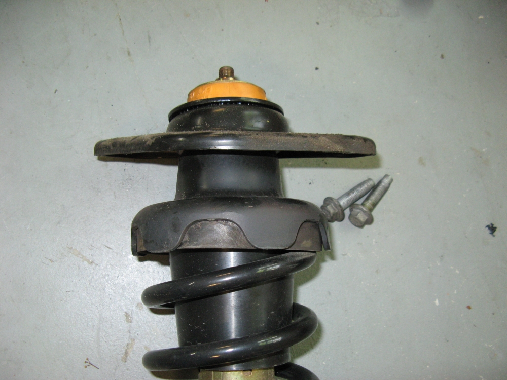
The front struts are an inverted design and use an internal bumpstop so the OE bump stop is not used. I did have to reuse the OE nut since the Bilstein supplied nut was larger and I could not get a socket down in the Hotchkis camber plate bearing holder to tighten. The rear shocks came with new bump stops.
The old struts must have been tired, these are a HUGE improvement. I don't think they ride rough at all and in fact might be a bit smoother since they actually work
My installation write-up for both springs/OE dampers can be found HERE, same process was used for this installation.

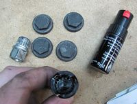
I finally got fed up with the OE wheel lock plastic caps. I used some old VW black paint to paint the center of the lock so it blends in without caps.
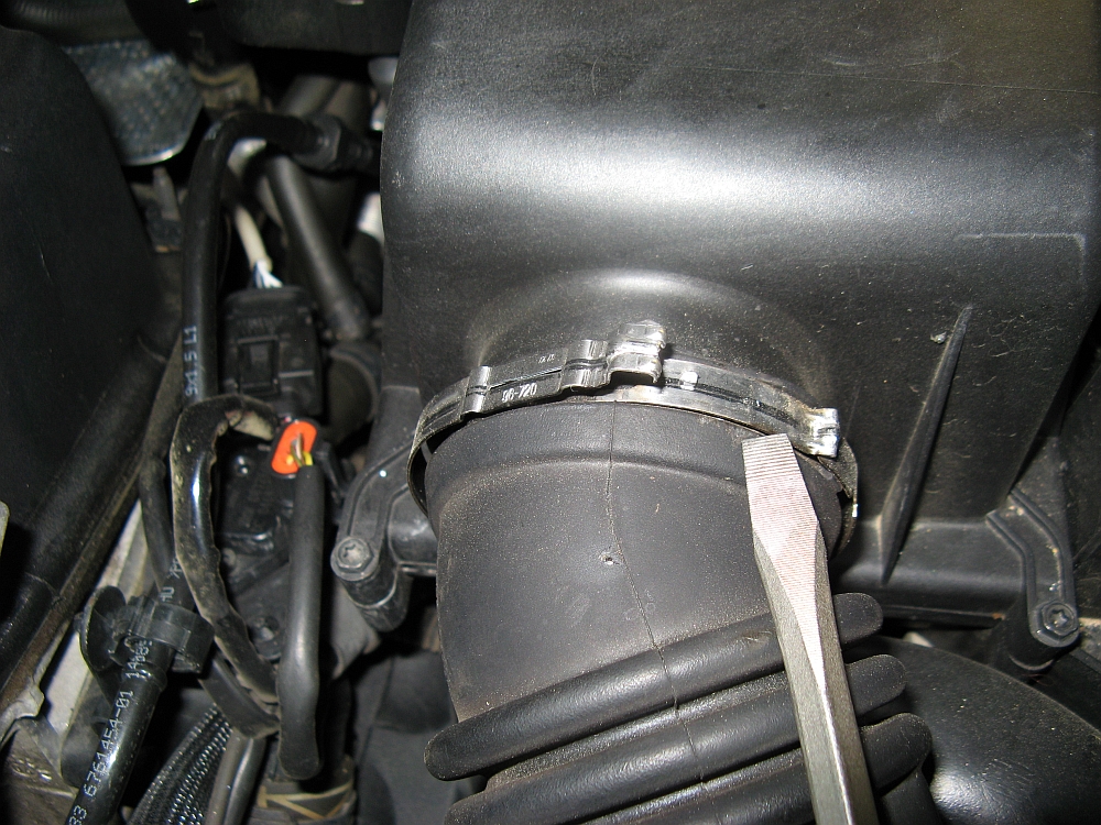
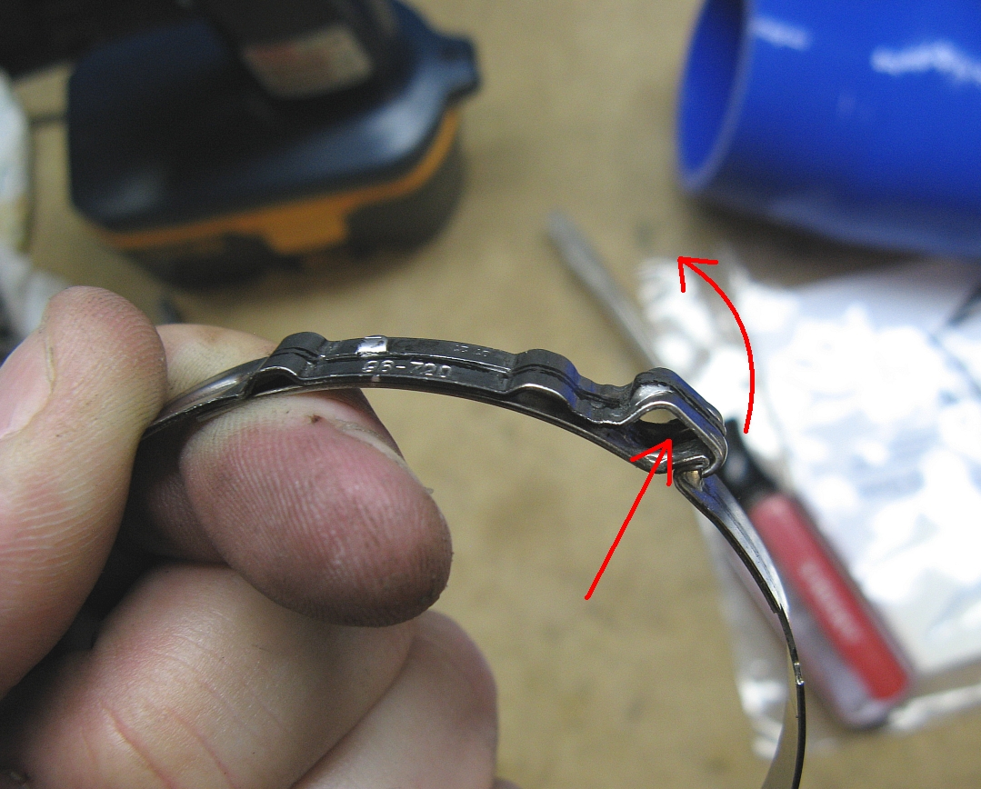
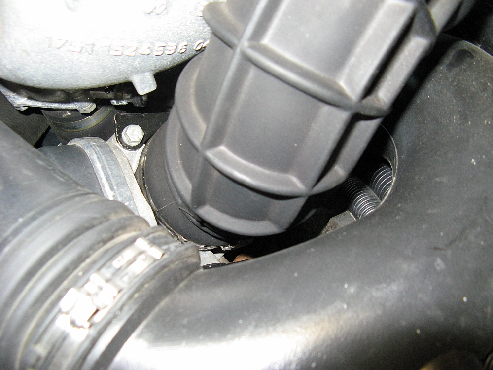
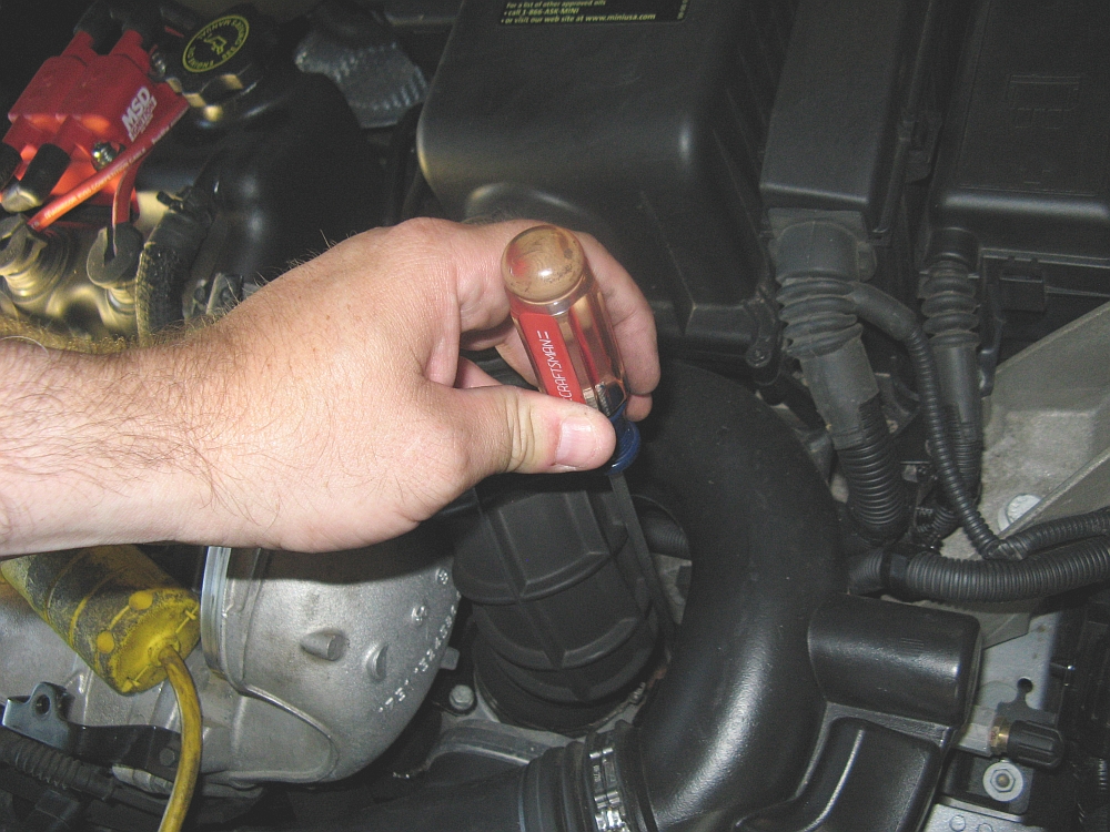
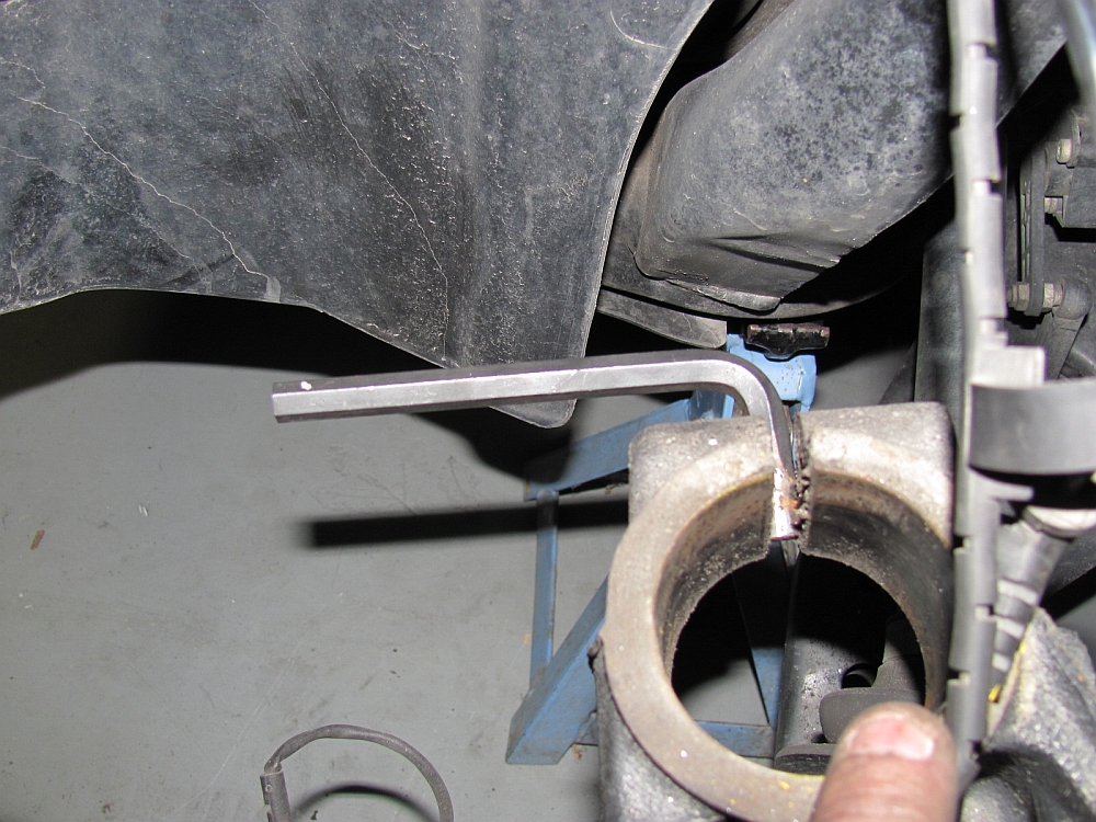
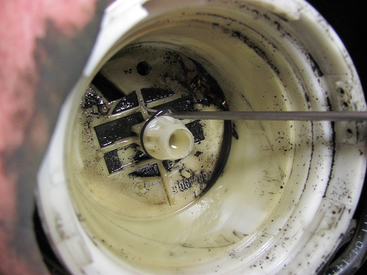
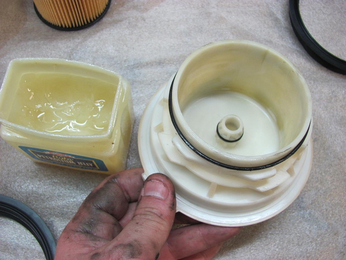
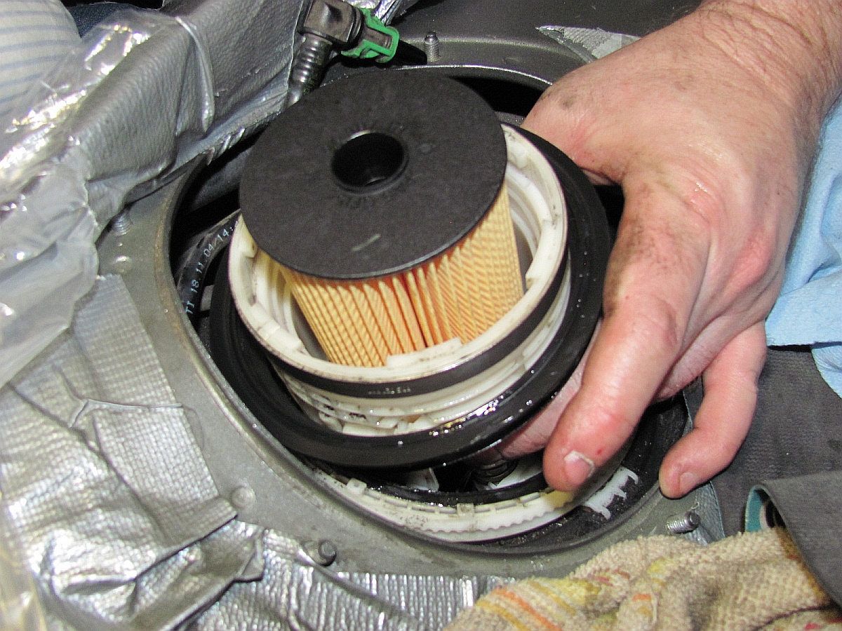
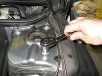
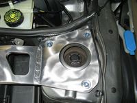
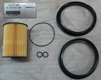
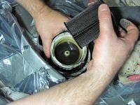
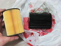
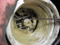
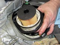
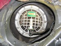
Trying to catch up on some maintenance items, I purchased the Mini fuel filter kit from WayMotorWorks and spent a Saturday afternoon replacing mine. It was LONG overdue at 141k miles and 6 years, even though Mini considers this a lifetime part.
My Fuel Filter Replacement DIY Guide can be found HERE.

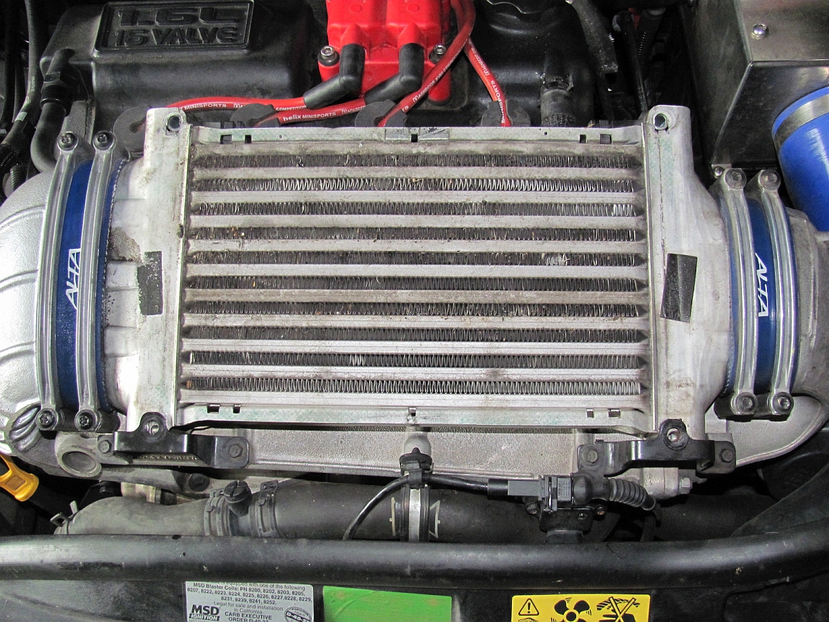
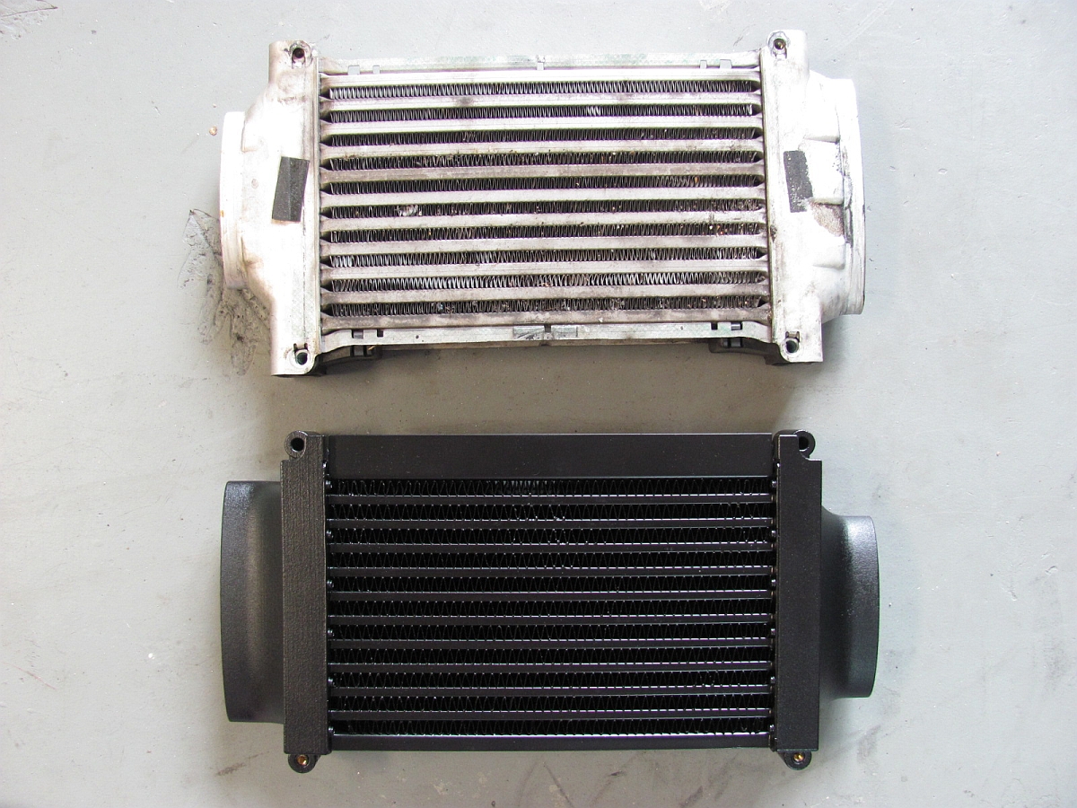
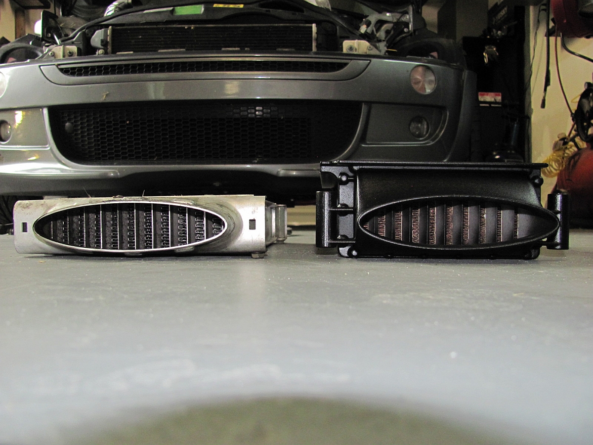
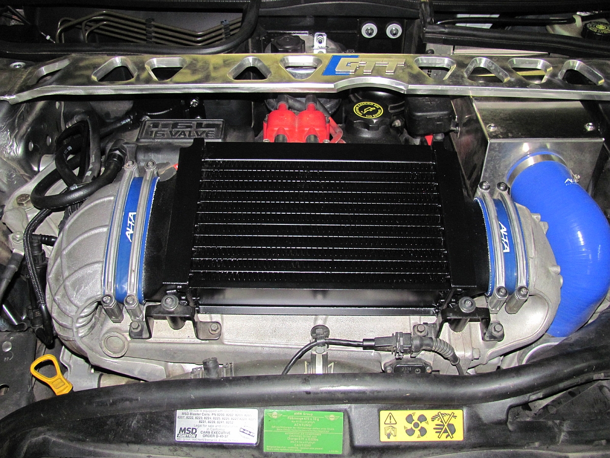
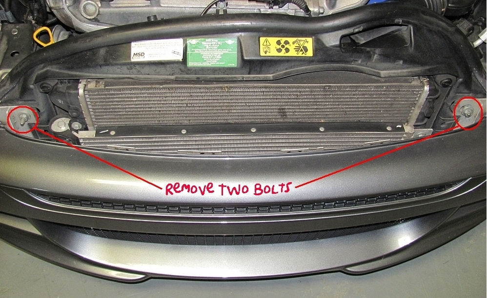
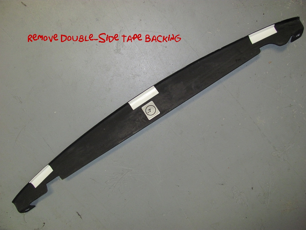
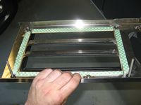
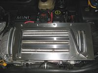
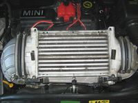
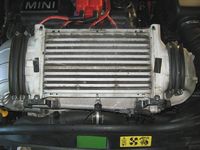
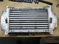
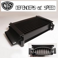
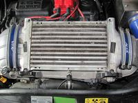
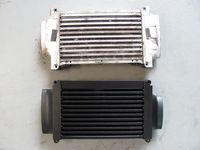
Intercooler from Defenders of Speed installed (archived ad HERE).
Tested to be more efficient than the Mini GP intercooler, I thought this would be a nice upgrade- forum discussion HERE.
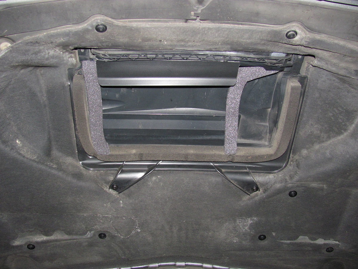
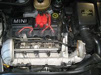
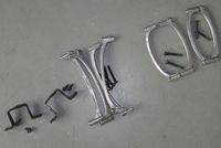
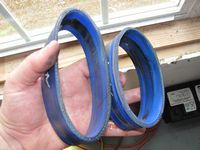
Installation is fairly simple: remove OE diverter and intercooler, attach brackets to new intercooler, install intercooler using old and provided new hardware. I did not follow the instructions to remove the factory foam seal but chose to leave it in place and add the provided foam seal to it, it works well. I was also missing the rubber piece attached to the plastic air guide bolted to the hood/behind the scoop that directs air to the intercooler. I found a door seal at Ace Hardware for a few dollars and cut it to the size I thought would work after measuring through the scoop, attached using E6000 adhesive. It looks more simple installed when compared to the stock intercooler and aftermarket diverter but does the job- good things come in small packages with the DOS intercooler. The intake side horn from the intercooler to the intake manifold feels cold after driving hundreds of miles on the highway and after aggressive blasts in the North GA mountains or on the Dragon/Hellbender.
Original DOS installation instructions can be found HERE, revised instructions HERE.


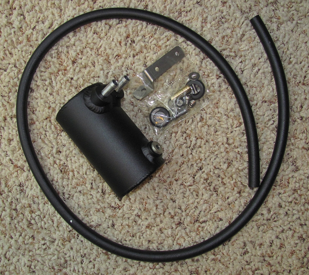
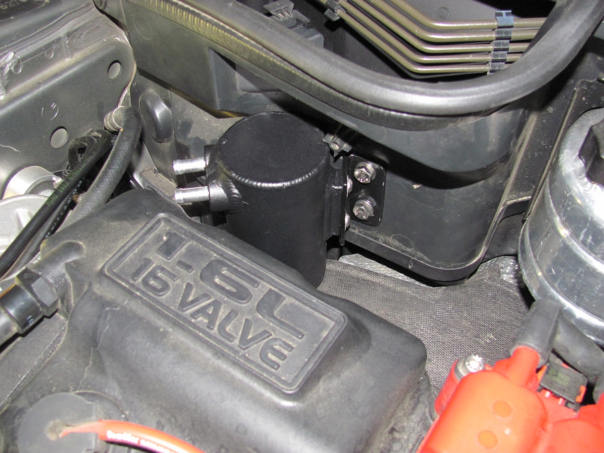
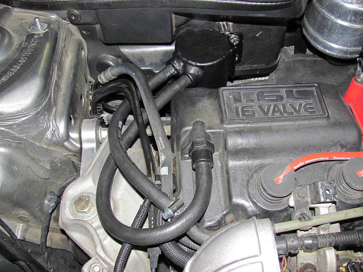
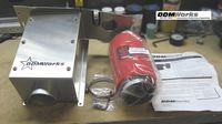
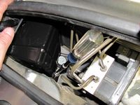
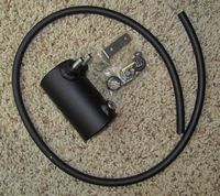
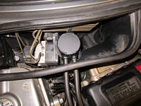
Oil Catch Can from BSH Speedshop installed (archived ad HERE).
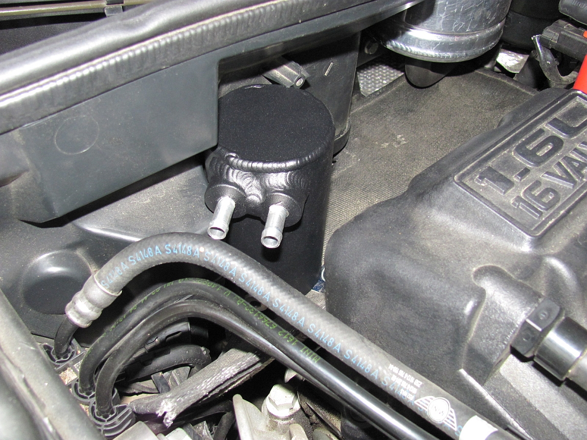
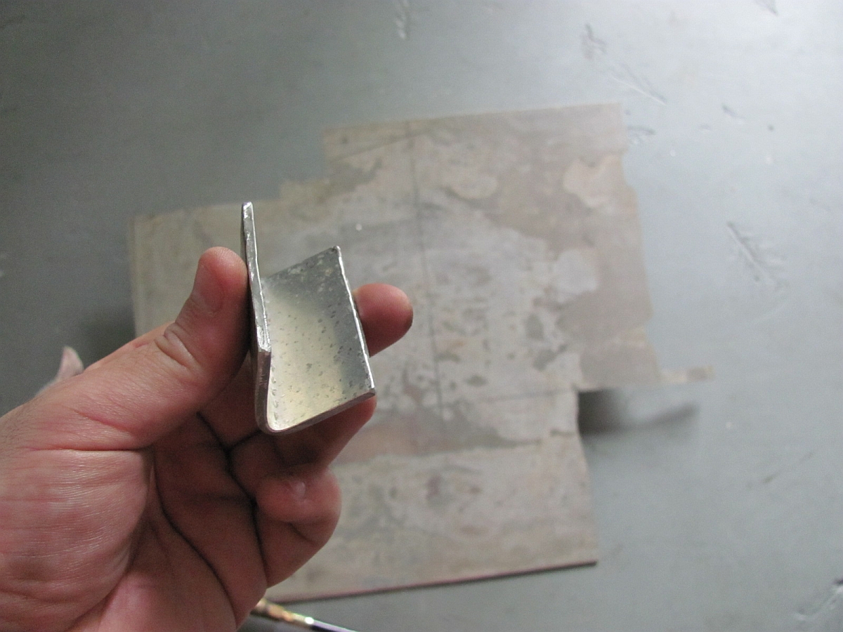
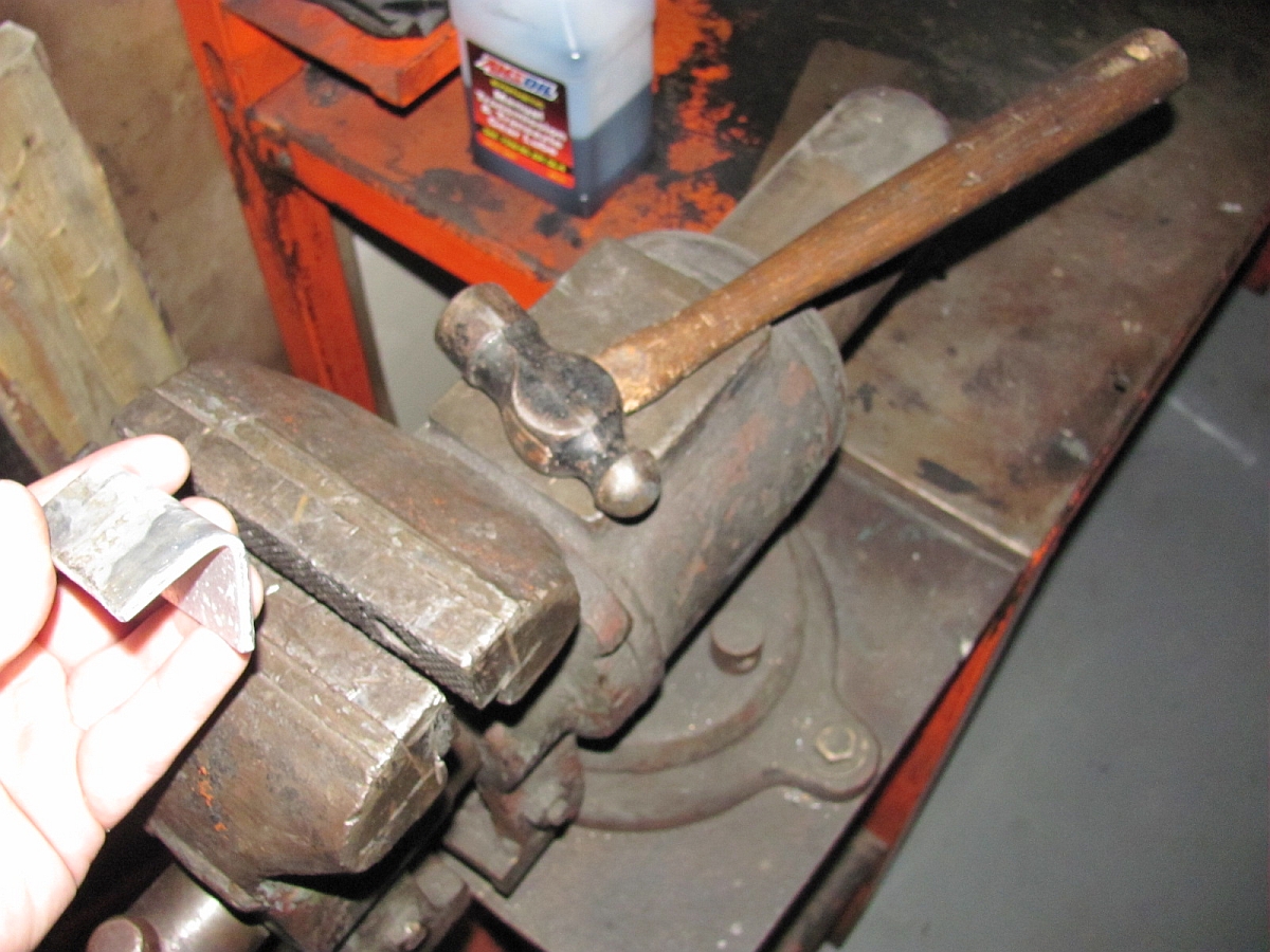
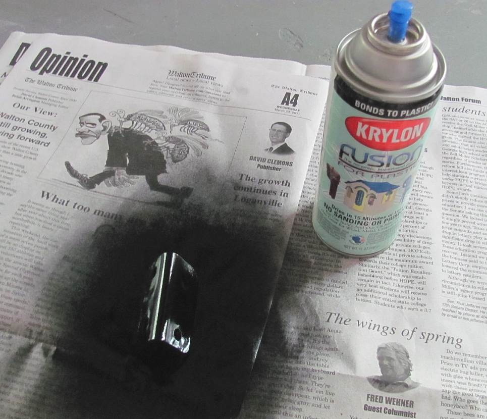
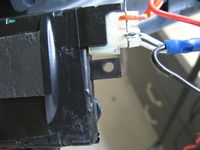
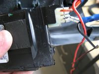
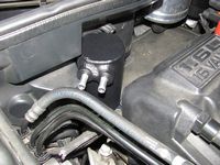
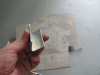
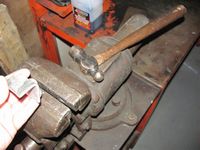
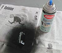
There is considerable discussion on the forums about how the R53 does NOT need an oil catch can but after finding some oil in the intercooler and on the intercooler boots, I decided this could only help and for the price was a no-brainer to keep the intercooler clean and efficient. The one small caveat is that the BSH catch can was designed to mount where the OE alarm siren would mount- no big deal if you don't have or want the alarm but I had it. The alternative mounting location was one I found on the forums that Randy Webb used, but required a bracket to be fabricated and the purchase of some additional stainless steel mounting hardware. I used a hack saw to cut a small piece of aluminum and then a vice and ball-peen hammer to shape. After trial fitting and drilling I painted it black using Krylon Fusion spray paint. The bracket is bolted to the catch can with the supplied bolts and I sourced stainless steel nut/bolts/washers- you will have to drill two holes in the plastic to mount it. I also found the push on hose to be tight on the PCV valve and the two can ports but not so tight at the union to the OE hose so I used the provided clamp there instead. I think it turned out pretty nice, we will see at the next oil change how much good it did based on how much it caught. I already notice the oil is no longer seeping through the silicone intercooler boots so it appear to be working.
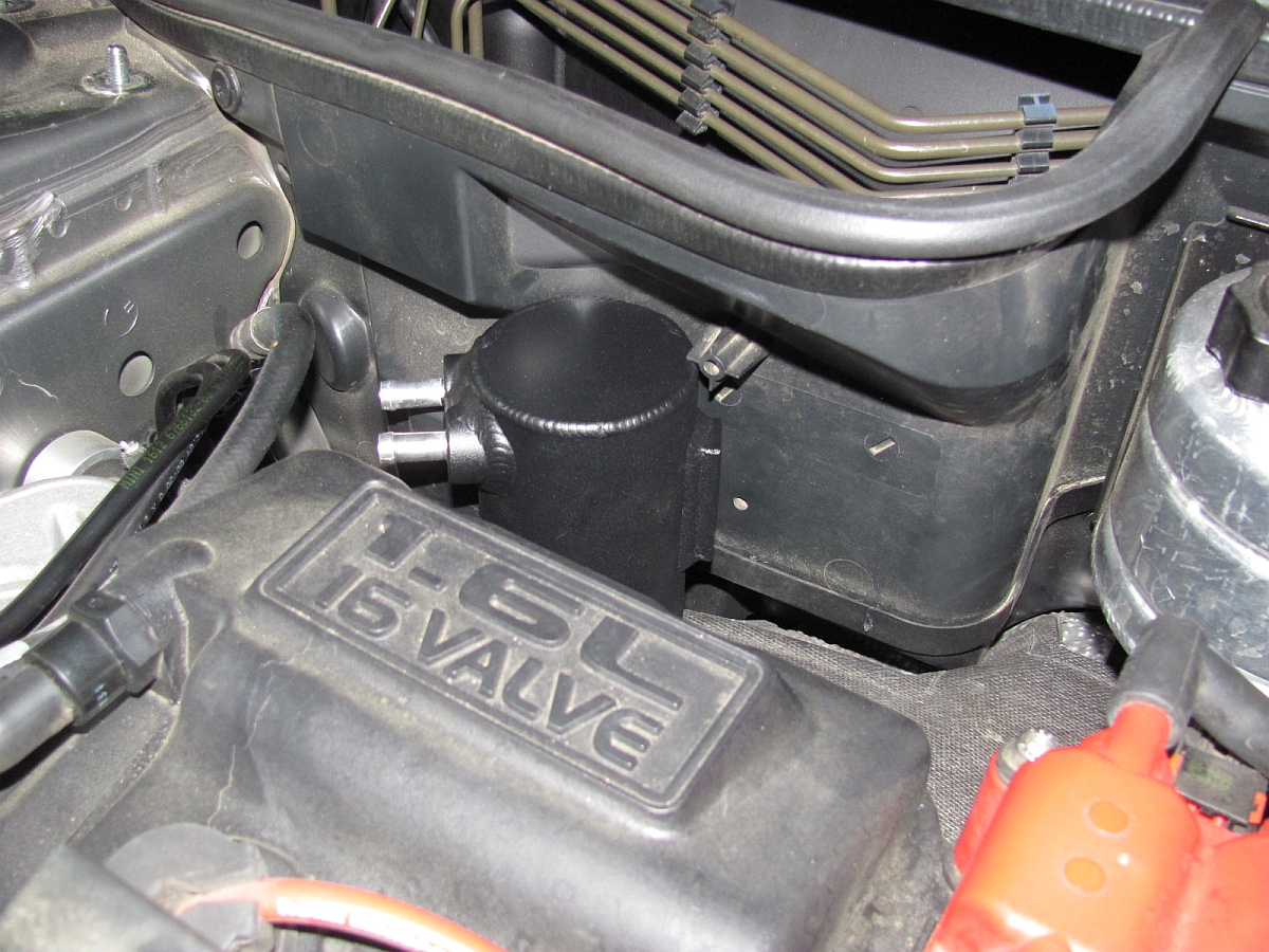
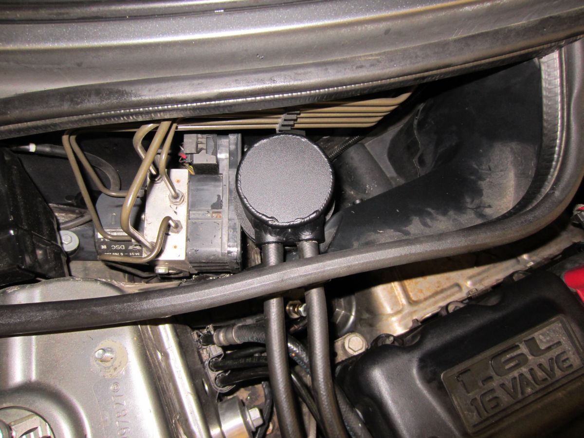
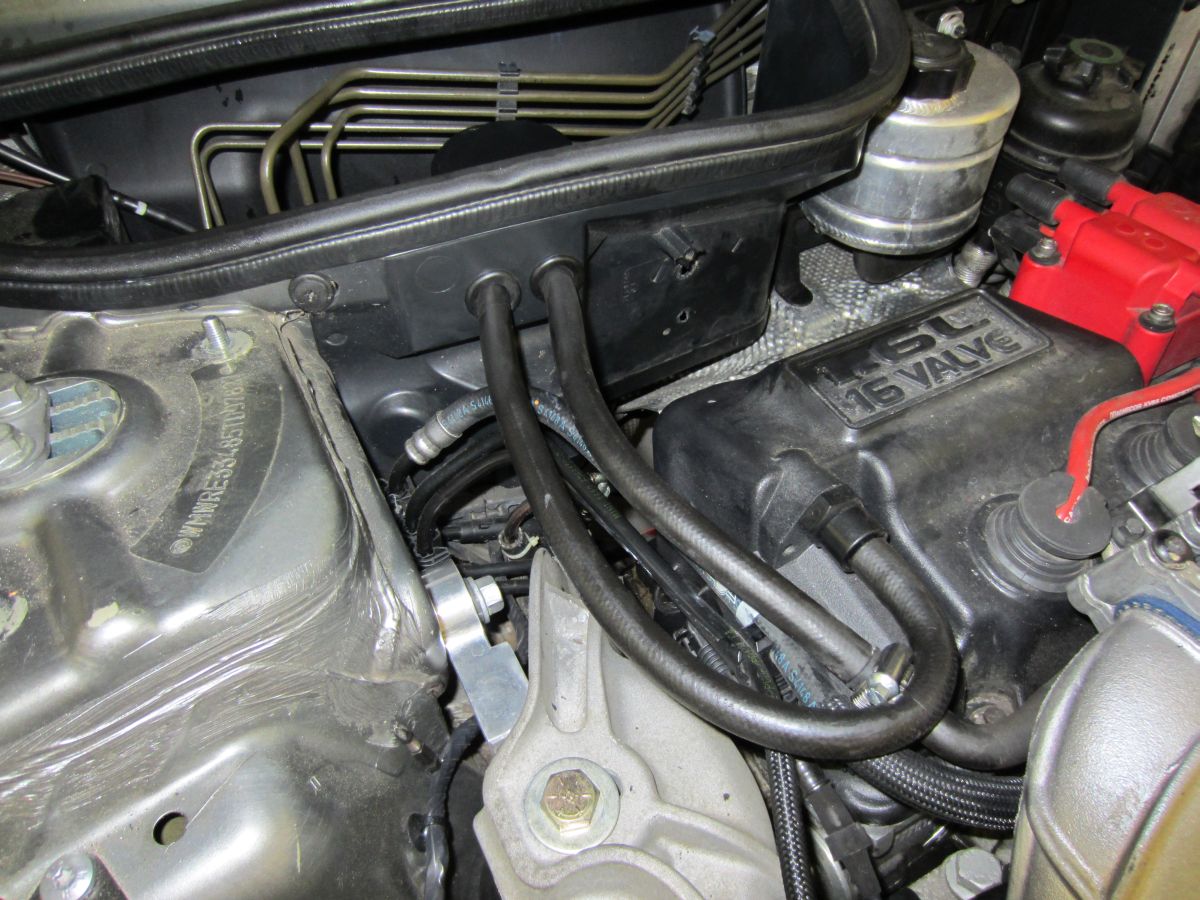
BSH installation instructions can be found HERE.UPDATE: After some time, I've decided to move the OCC to a cooler area- it does not appear to do ANYTHING mounted over the exhaust. The prior mounting holes were plugged with plastic screw rivets. Using a few wraps of foam weather-stripping and the tension from the push-on hoses through the grommets, the new location is very stable and should be cooler- we'll see if it does a better job. BSH customer service blows though, I have sent a few emails with no response, YMMV.
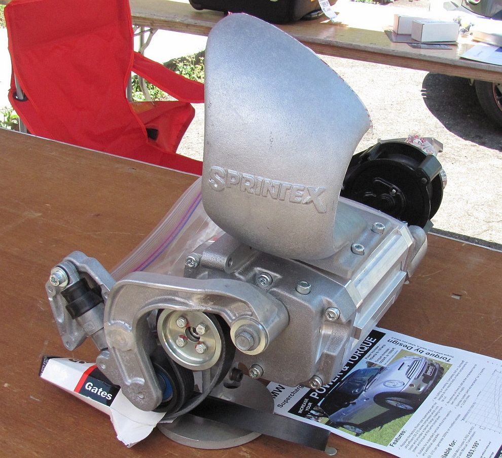
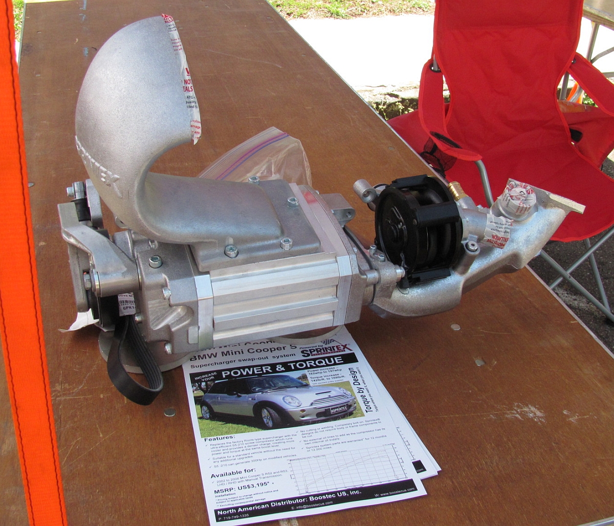
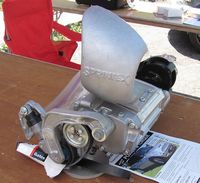
I didn't have a lot of time this year to go to the 2011 Minis on the Dragon GTG but was able to squeeze in some time Friday to join the car show and check out the vendors as well as other Mini owner's cars. I got to see the new Sprintex supercharger and was able to get some photo ops on the way out:


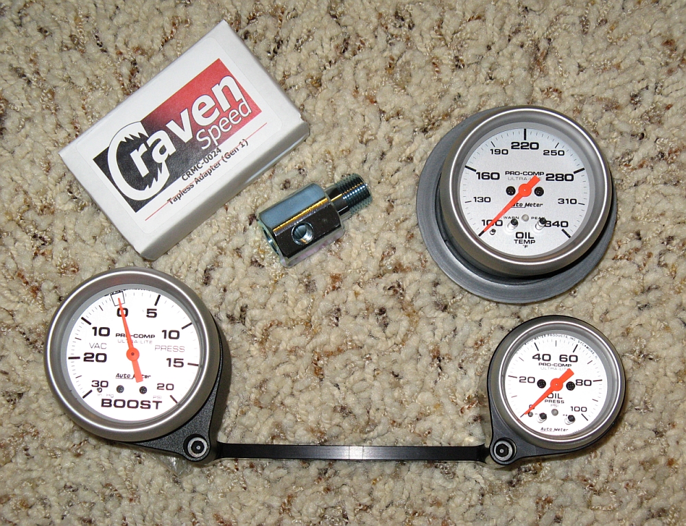
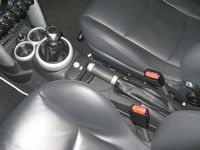
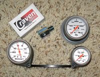
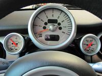
Cravenspeed X Mount/52mm Gauge Pods/Oil Pressure Sensor Adapter CRMC-0024 and Autometer Gauges (Boost 4377, Oil Pressure 4353) installed. I started out with the larger 2 5/8" mechanical boost gauge (Autometer 4401) but decided I didn't like it after a week and replaced it with the electric gauge. The oil temp gauge and vent mount are still a pending project.
My installation write-up is HERE:
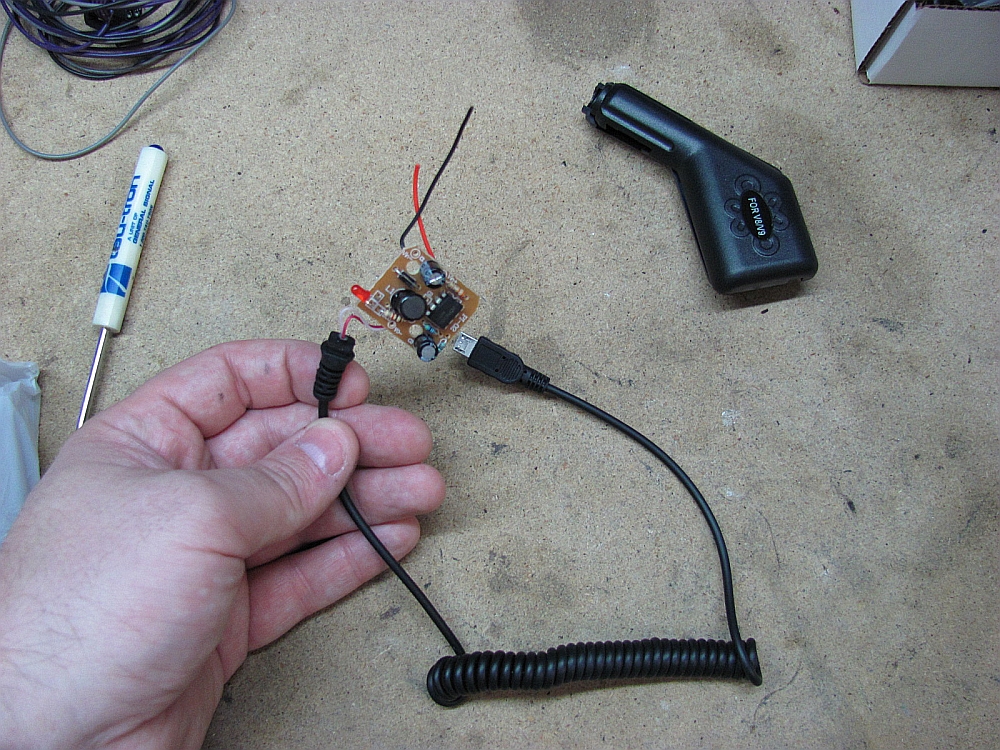
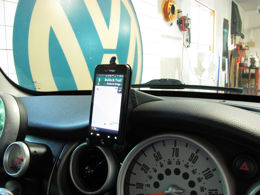
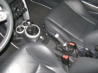
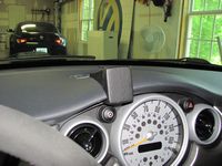
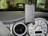
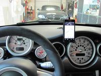
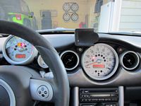
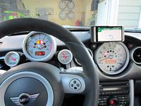
Kuda dash mount (P/N 292325) installed along with hard wiring a micro-USB cable for my HTC Incredible. I have been placing the phone in the cup holder and while that is functional, if I am using Google Maps for navigation that is way out of my line of sight. Not to mention if the phone is sitting in the cup holder there is no room for my morning cup of coffee or horchata. If you have never heard of horchata, it is a traditional Mexican drink that you can try by making this horchata recipe at home. I decided to go ahead and hard wire a power plug as well while installing the gauges above since the wires were there and the dash was open. I found the new Kuda mount on the NAM classifieds at a discount and sourced the 12v micro-USB adapter and phone clip on eBay for $8 shipped. Total cost for everything was under $50.
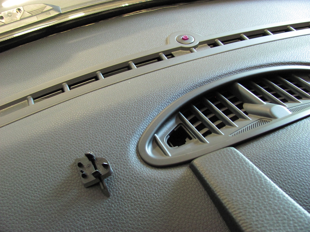
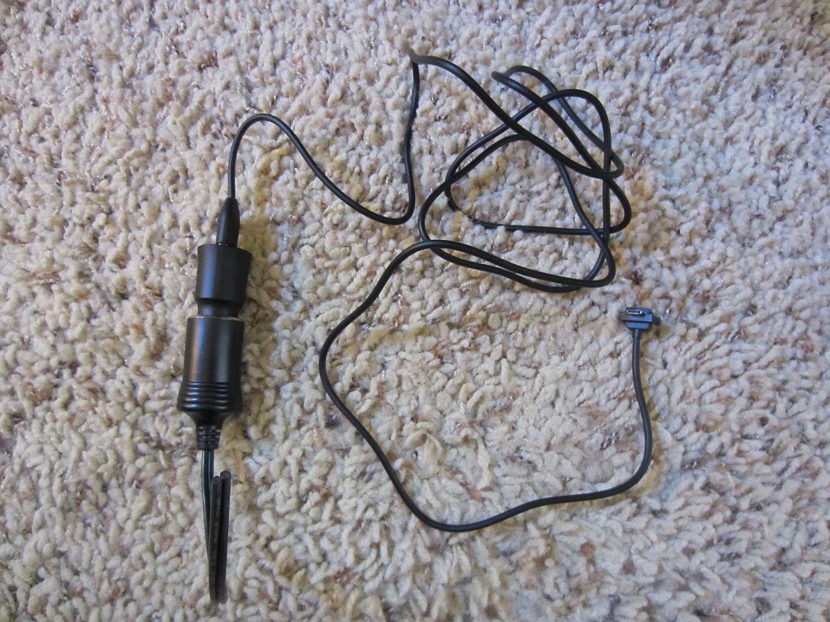
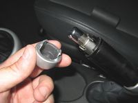
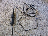
The cigarette lighter plug was disassembled and the wires cut from the contacts- I then extended the 12v+ and ground wires so I could wire them in with the gauges. The lighter plug casing can be cleaned out and reinstalled over the circuit board, feeding the wires out of the + contact hole. I removed the trim around the speedo and vents and made a small hole with a Dremel tool and routed the wire and plug around the vent and out of the hole.
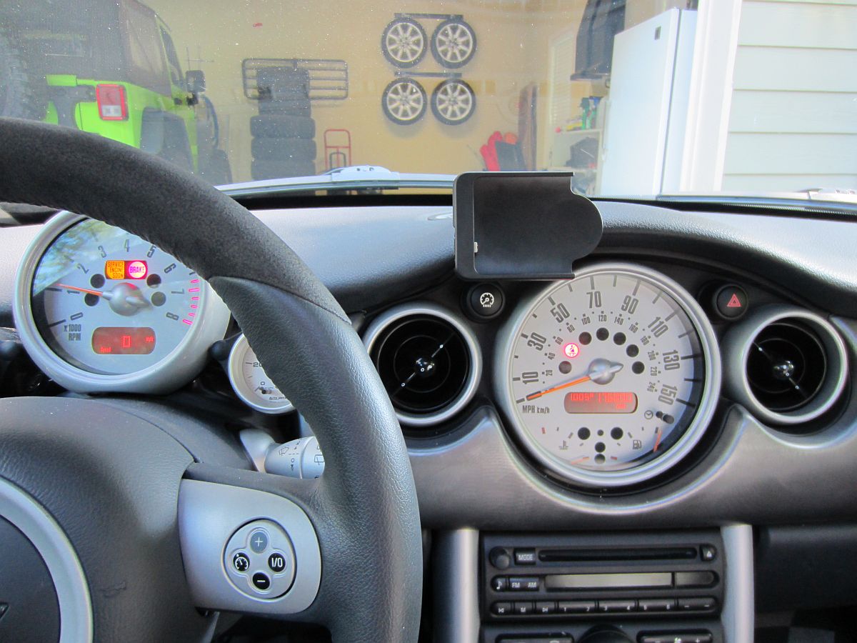
Next the Kuda mount was installed, a little trickier than the instructions make it sound. You kind of have to gorilla it into place but once there, it is not moving, even without the screw securing the upper tab. I did remove the access cover on the driver side to see where the upper tab was going and position the mount so that it did not interfere with the access cover tabs, it just snaps out/in.
The eBay phone holder was the belt clip type, I used a Dremel tool to remove the belt clip and make the rear of the holder flush. I also had to notch it for the power plug, the holder is meant to be used with the phone facing in and NOT connected to power. Since I may not always have this phone, I wanted to be able to potentially remove this mount and install another later. To do this I attached the phone mount to the Kuda mount using E6000 adhesive- it will not go anywhere while I want to use it but with some force I will be able to remove the mount and peel the adhesive off the Kuda mount to reuse. The mount was taped in place over night and and the adhesive allowed to cure. Any excess adhesive is easy to cleanup when when dry, it just peels up.
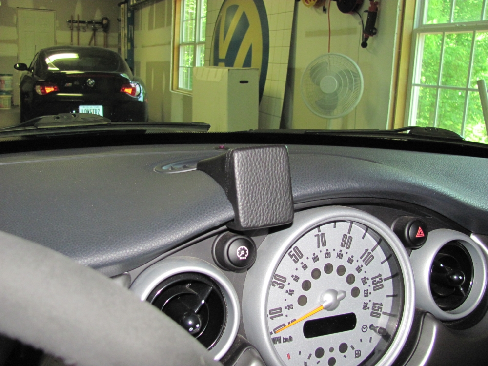
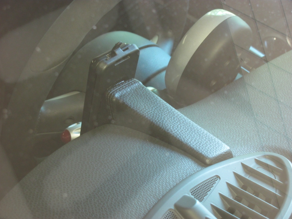
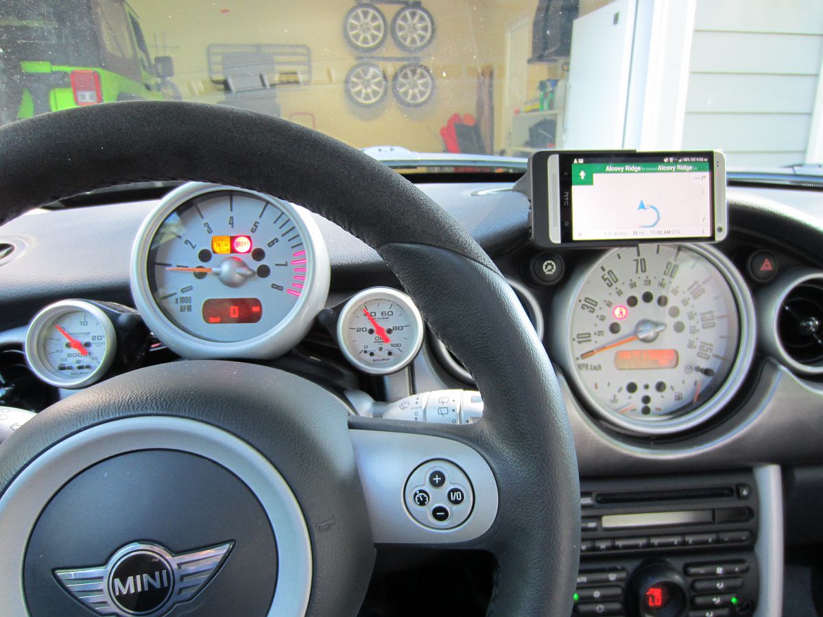
I think it turned out better than expected, the Kuda mount grain matches perfect with the dash and the color difference noticed in flash pictures is barely noticeable in reality (this is to be expected since the Kuda is covered in leather and the dash is plastic). Having the phone close and in my line of sight is MUCH better than the old cup holder method, I wish I had done this a long time ago.
[EDIT] This Kuda mount is now on it's 3rd phone dock, the E6000 adhesive makes this very easy, peel the old dock off, remove remaining adhesive, attach new dock with more E6000. I also went with a new wiring solution, since this dock came with a proprietary cord, and bought a 12v accessory plug so no soldering- much cleaner.
Also found the Mini Cooper Dash Disassembly instructions HERE.
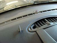
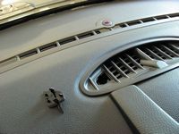

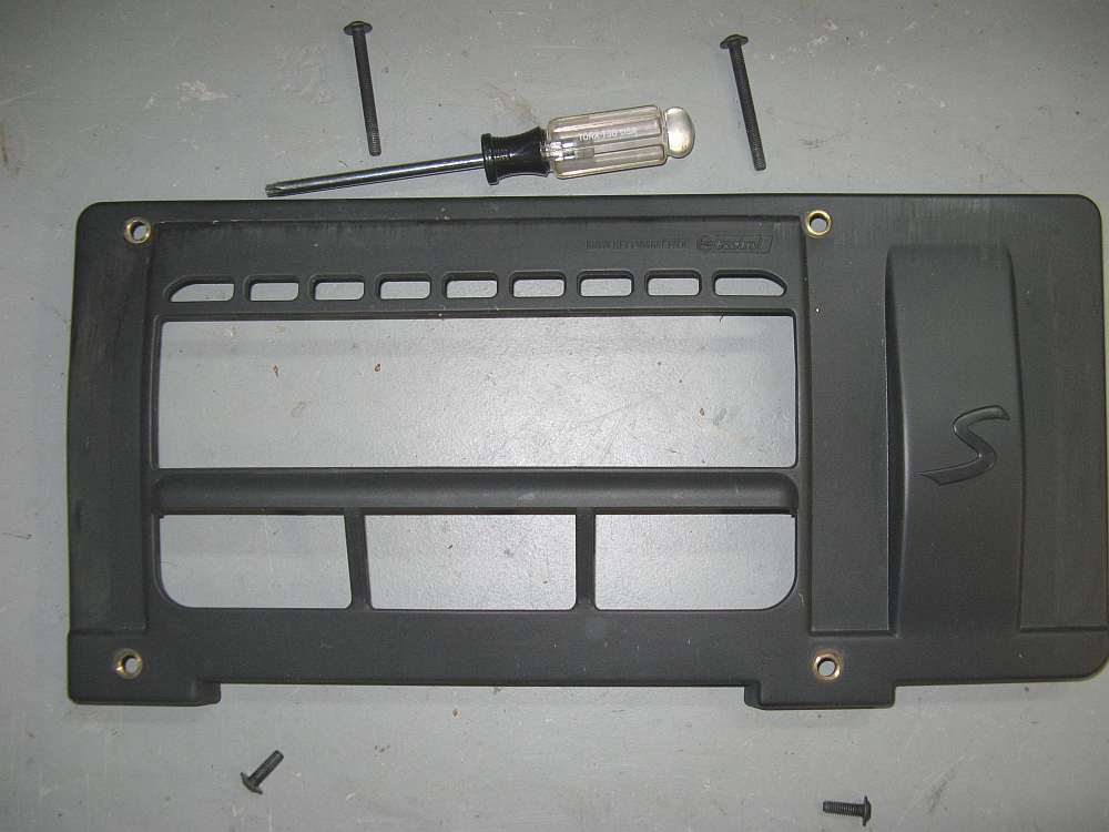
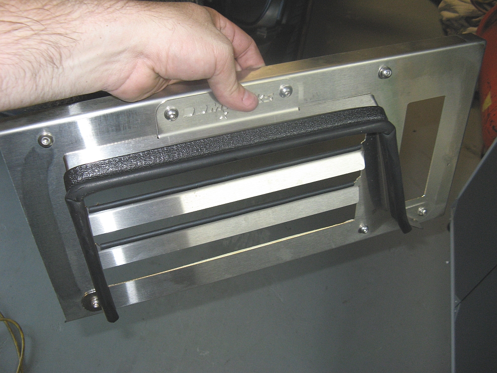
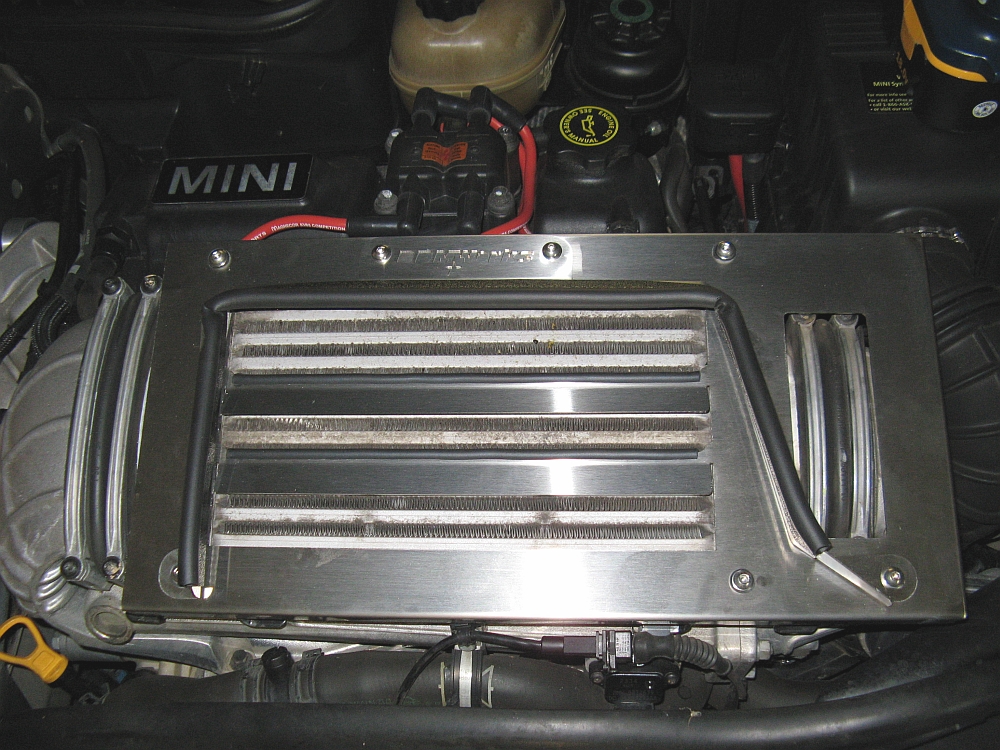
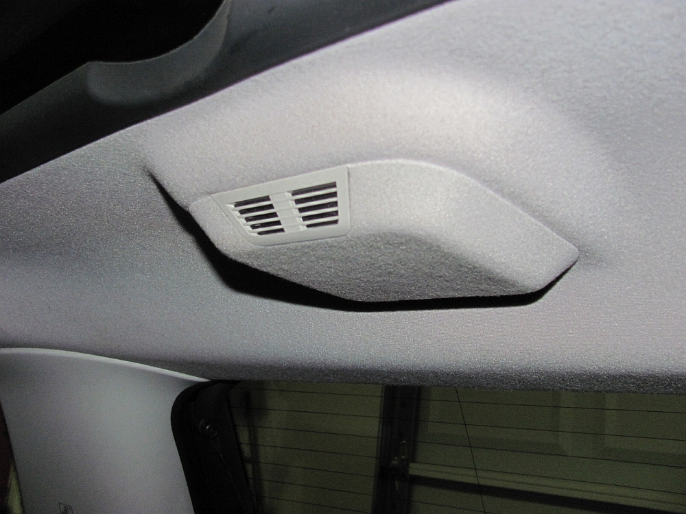
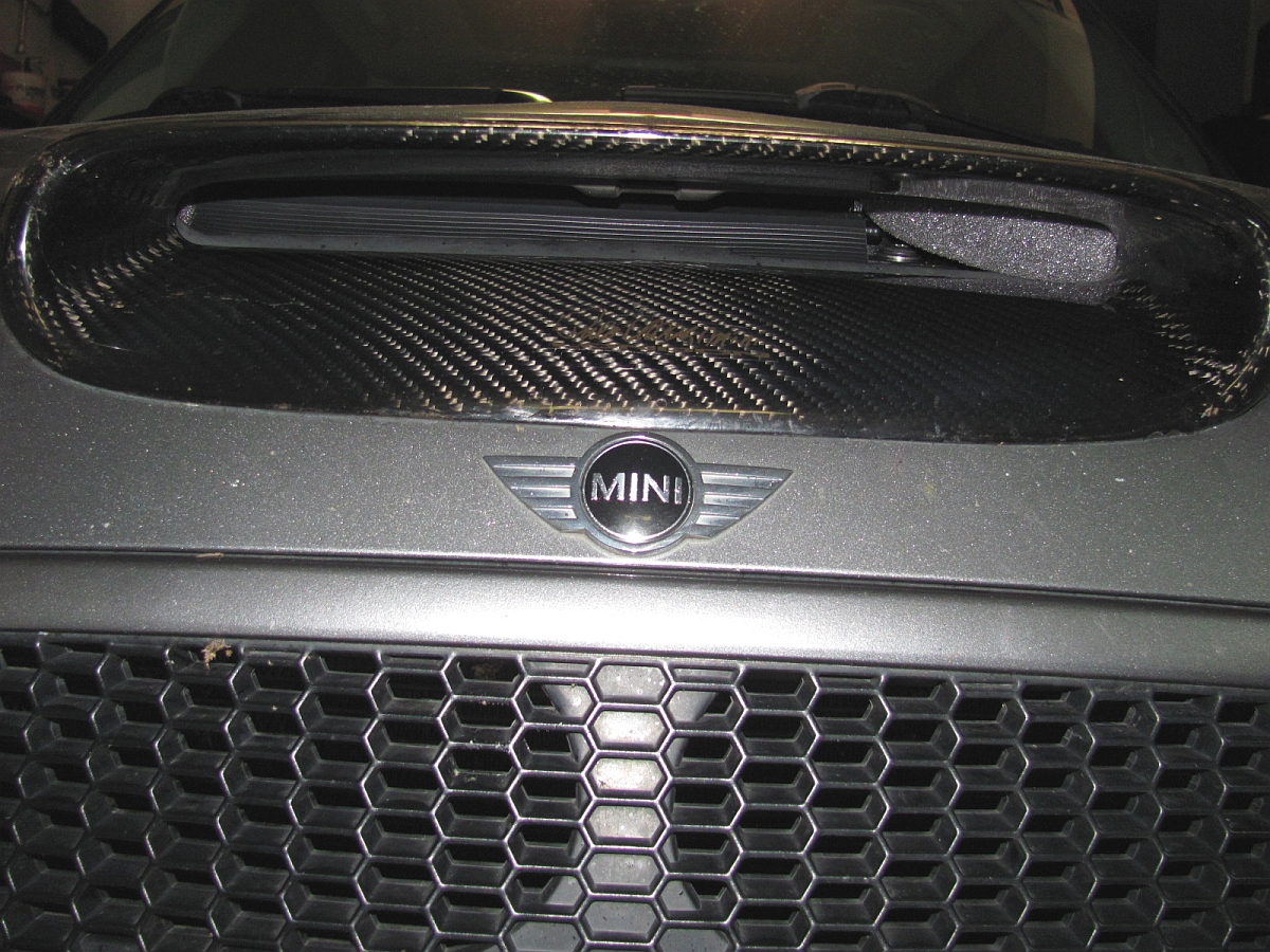
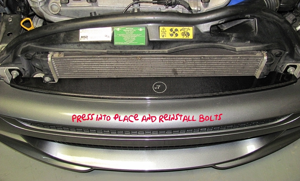
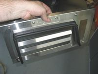
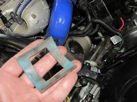
M7 Air Plate Diverter (APD) in carbon fiber installed. M7 Development Notes can be found HERE.
Ideally this piece will provide better airflow, but it will also keep tools from falling through the gap and looks a lot better too.....plus it's carbon fiber, Icarbon fiber
M7 APD Installation Instructions are HERE.
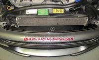
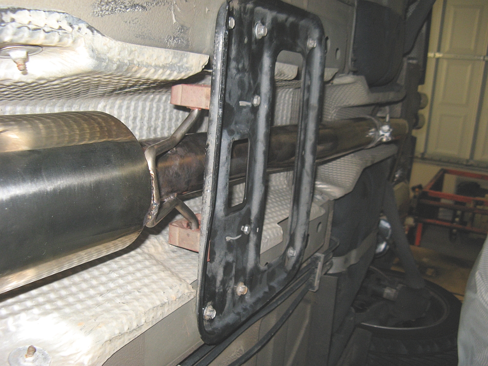
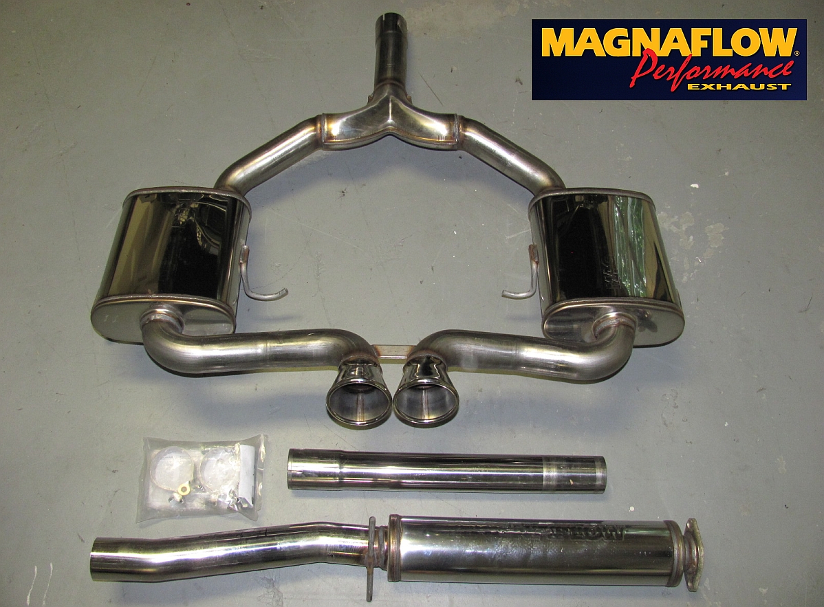
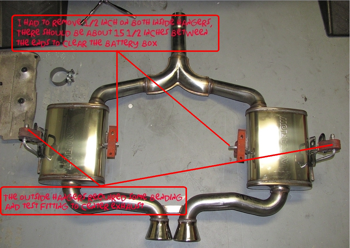
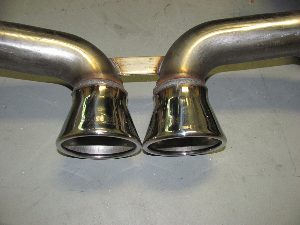
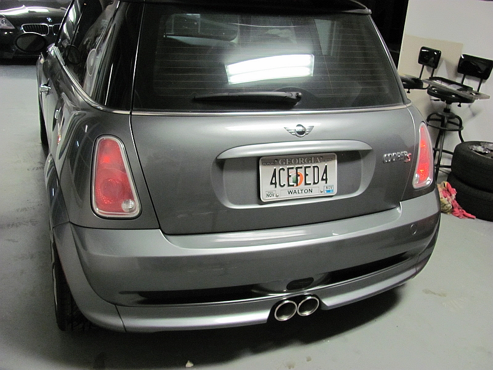
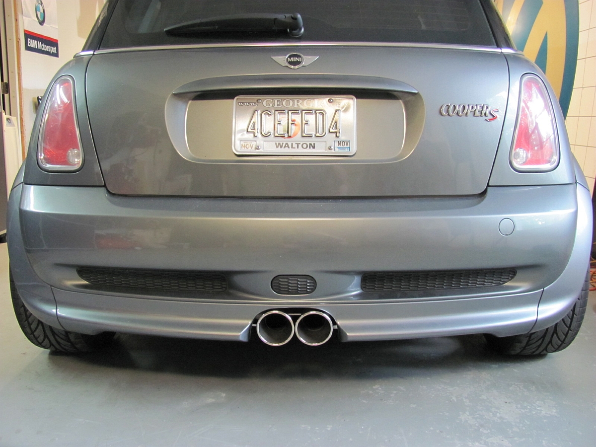
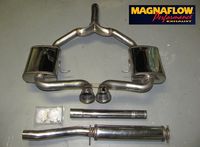
MagnaFlow Exhaust (P/N 16662) installed. I got used to the IE exhaust I had installed and was looking for something more aggressive sounding. The dyno numbers were appealing as well.
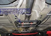
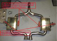
It did require some fitting: I used my die grinder/cutoff wheel to remove about 1/2" of the inside hangar rods so they would clear the battery box (measures about 15.5" tip to tip to clear the heat shield around the battery box, the outside hangars required some bending and test fitting to get the exhaust centered, and I had to use some 5/8" washers to shim the hangers down so that the tips were not touching the valance. I also decided I wasn't happy with the rubber vacuum plug on the end of the resonator hanger rod on the driver side and used a hack saw to trim it down about 1/2" so it would not contact the heat shield. But after the adjustments, the tips are perfectly centered and do not touch the valance, about 1/4" clearance at the top and more on the sides. Pictures below highlight some of these adjustments.
After my first test drive I find the exhaust to be more sedate than the IE I removed, but I'll give it some time to burn in and review the sound then, it should get deeper after some miles and the glass packing burn in.
Magnaflow Instructions HERE, Dyno HERE.

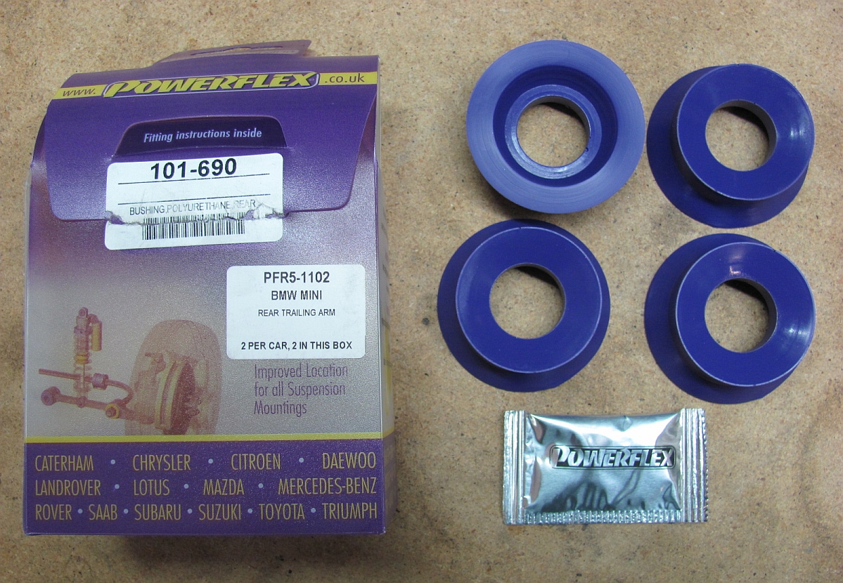
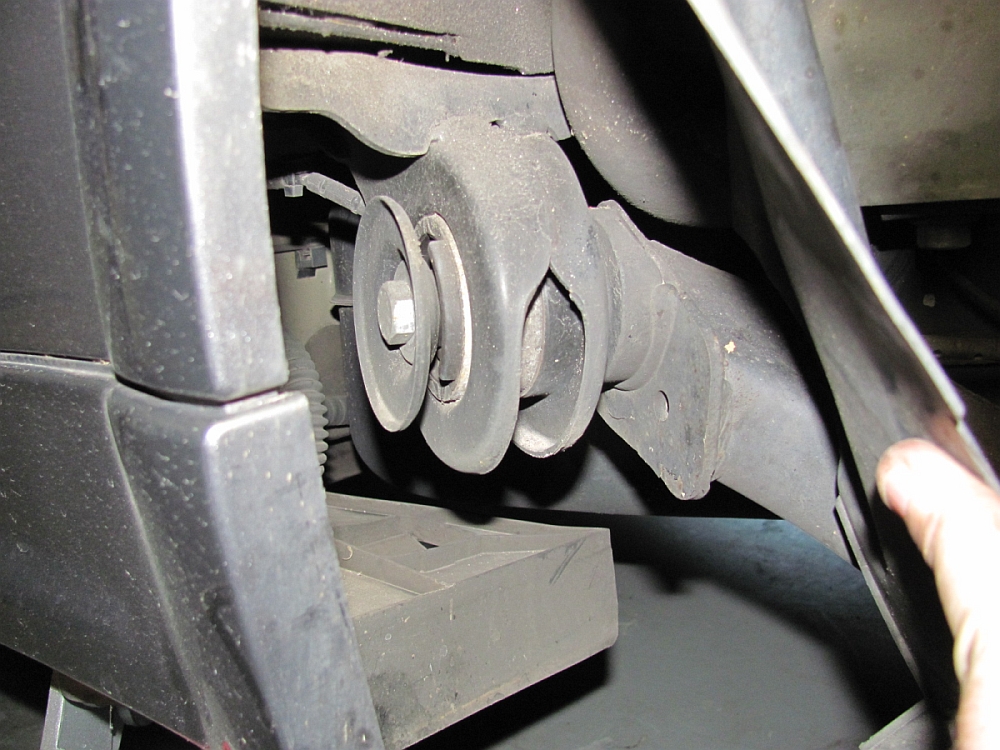
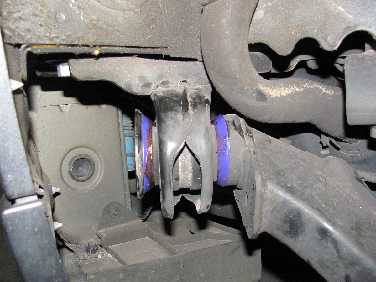
Powerflex Rear Trailing Arm Bushing Inserts (P/N PFR5-1102) from Way Motor Works installed. Some members on the NAM forum said it made a noticeable difference in rear-end wander with small bumps so for the low cost/effort I figured I would try them out. The rear control arms changed sometime in 2003 or 2004 so make sure you get the correct part number for your build date.
My installation write-up is HERE.
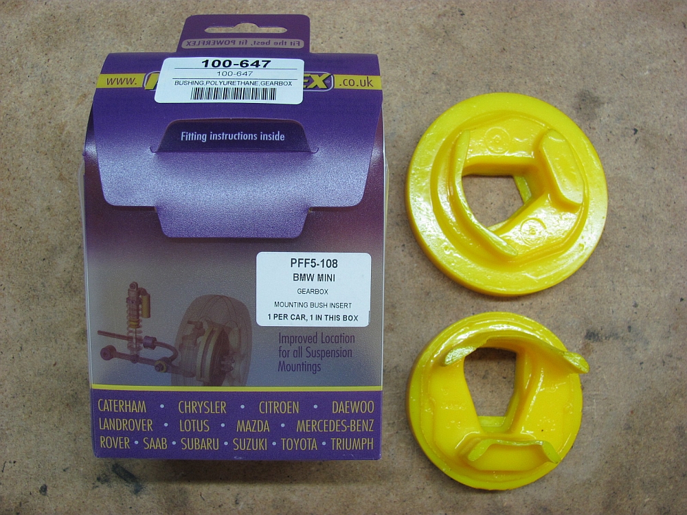
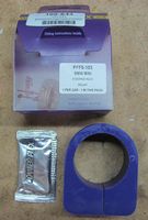
Powerflex Manual Gear Box (aka Transmission) Bushing Inserts (P/N PFF5-108) from Way Motor Works installed. I did not notice any additional NVH (but already have the other two "performance" mounts installed, if your other mounts are OE you may notice some NVH) and the car just feels more solid.
My installation write-up is HERE.


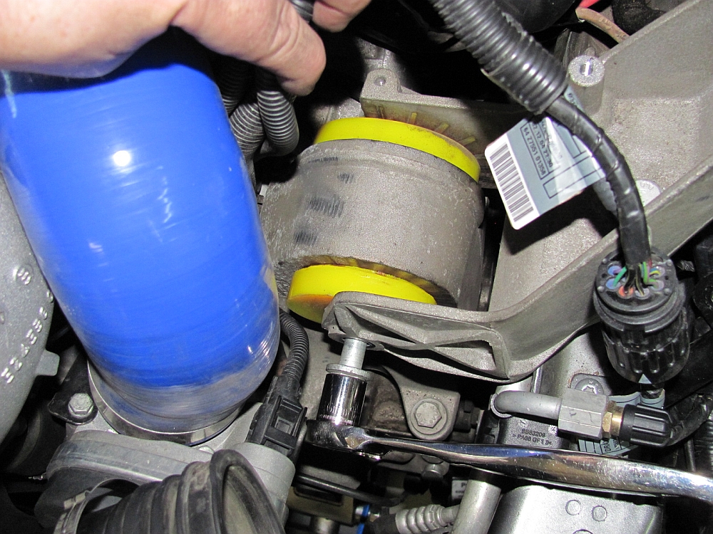
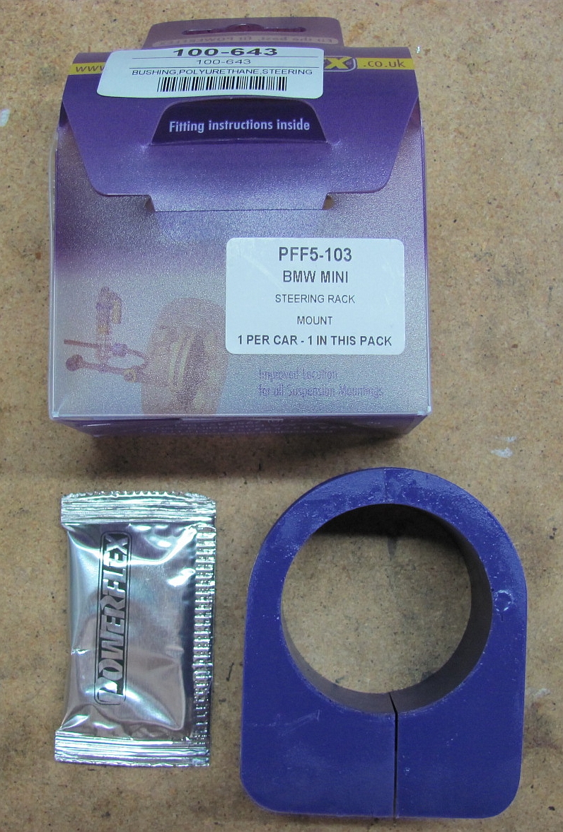
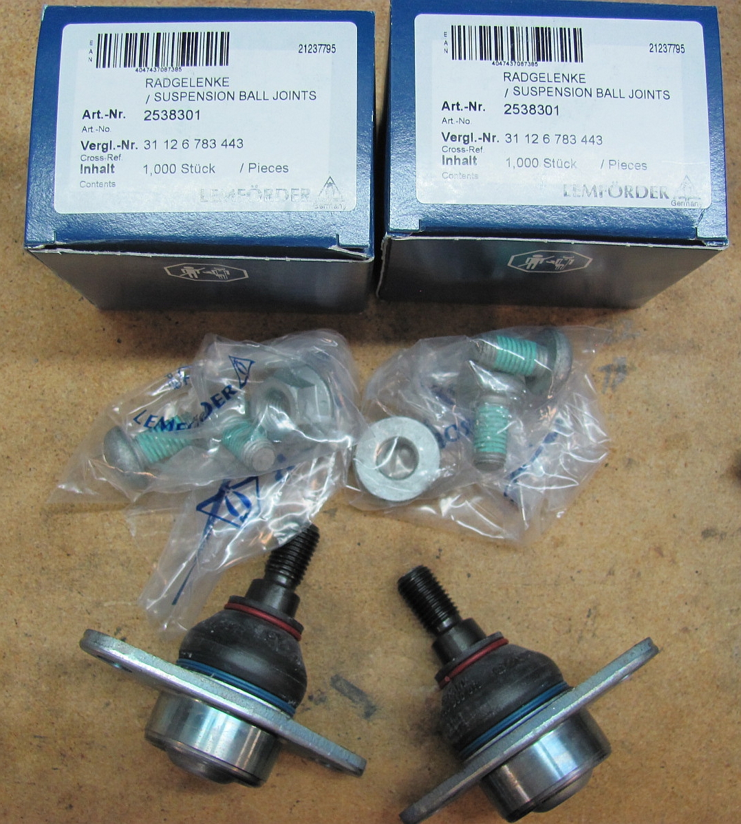
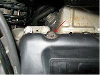
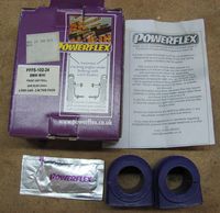
Powerflex Front Control Arm Bushings [FCABs] (P/N PFF5-101), Front R53 SwayBar Bushings (P/N PFF5-102-24), and Steering Rack Bushing (P/N PFF5-102-24) from Way Motor Works installed. I had purchased new Lemfoerder (OEM) front inner/outer control arm ball joints from Pelican Parts some time ago when they were on sale and I had a credit, but these can also be purchased from Way as part of his FCAB kit. If you are going to drop or lower the subframe for the control arm bushings you might as well do the rest while you're there.
I decided I needed new front control arm bushings when the front end started moving on its own during acceleration and braking, typically requiring some counter-steering to address. I know for sure I have put almost 40k miles on these and have no idea how long they were on the car before I bought it. The easy front control arm bushing test is to kick the tire and watch for movement. The passenger side was worse than the driver side, when jacked up I could also move the passenger side control arm by hand and watch the bushing move. I have a video HERE that illustrates how to diagnose a bad FCAB.
My DIY guide for replacing all of these components can be found HERE.
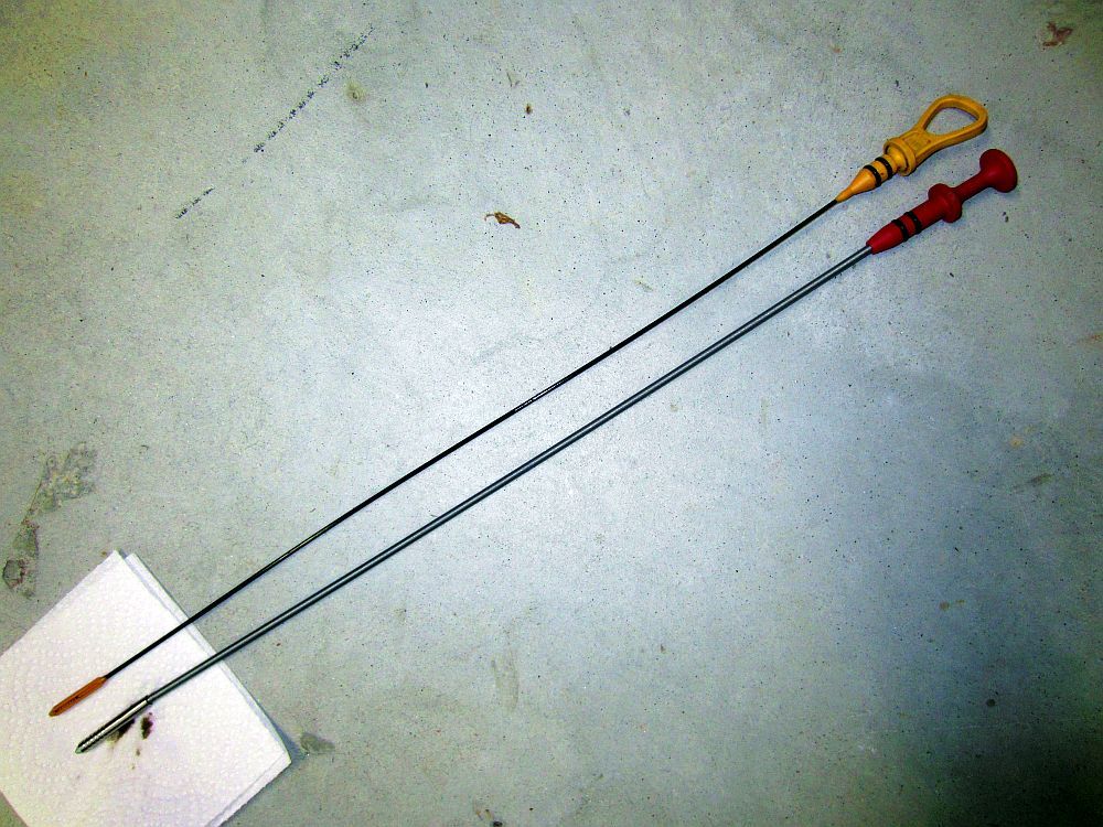
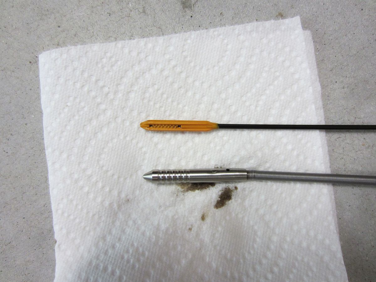
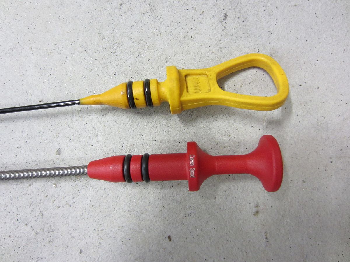
CravenSpeed dipstick from Way Motor Works installed. MUCH easier to use/read than OE and no worries about breaking it.


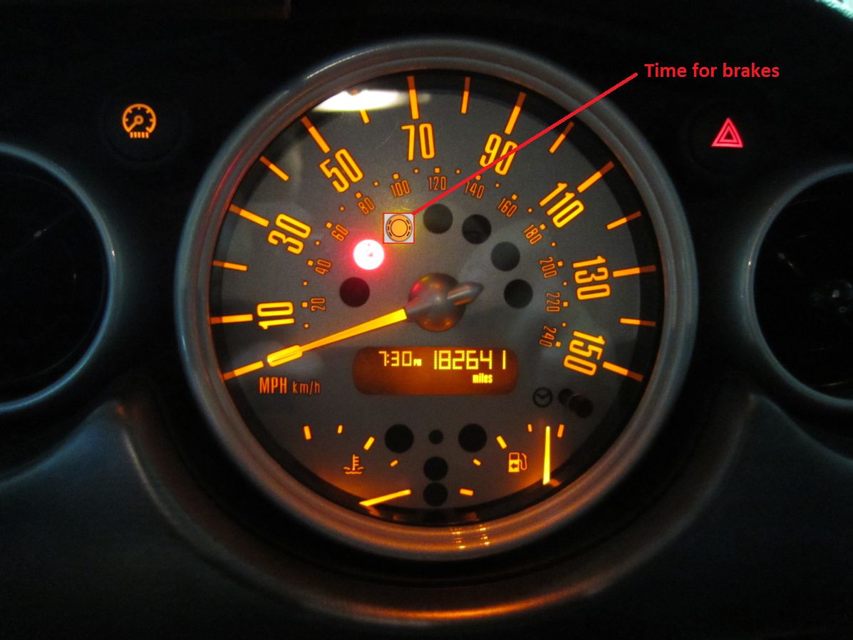
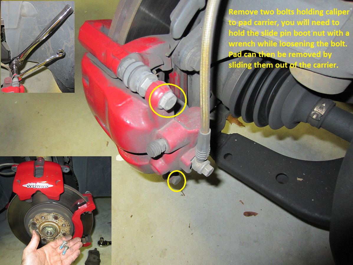
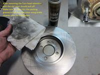
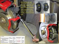
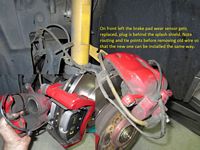
Time for front brake pads and rotors. Duralast Ceramic Pads (P/N DGC1204), Duralast Rotors (P/N 73013), and PEX Brake Pad Wear Sensor (P/N WK527) used as replacement parts for my JCW brakes.
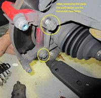

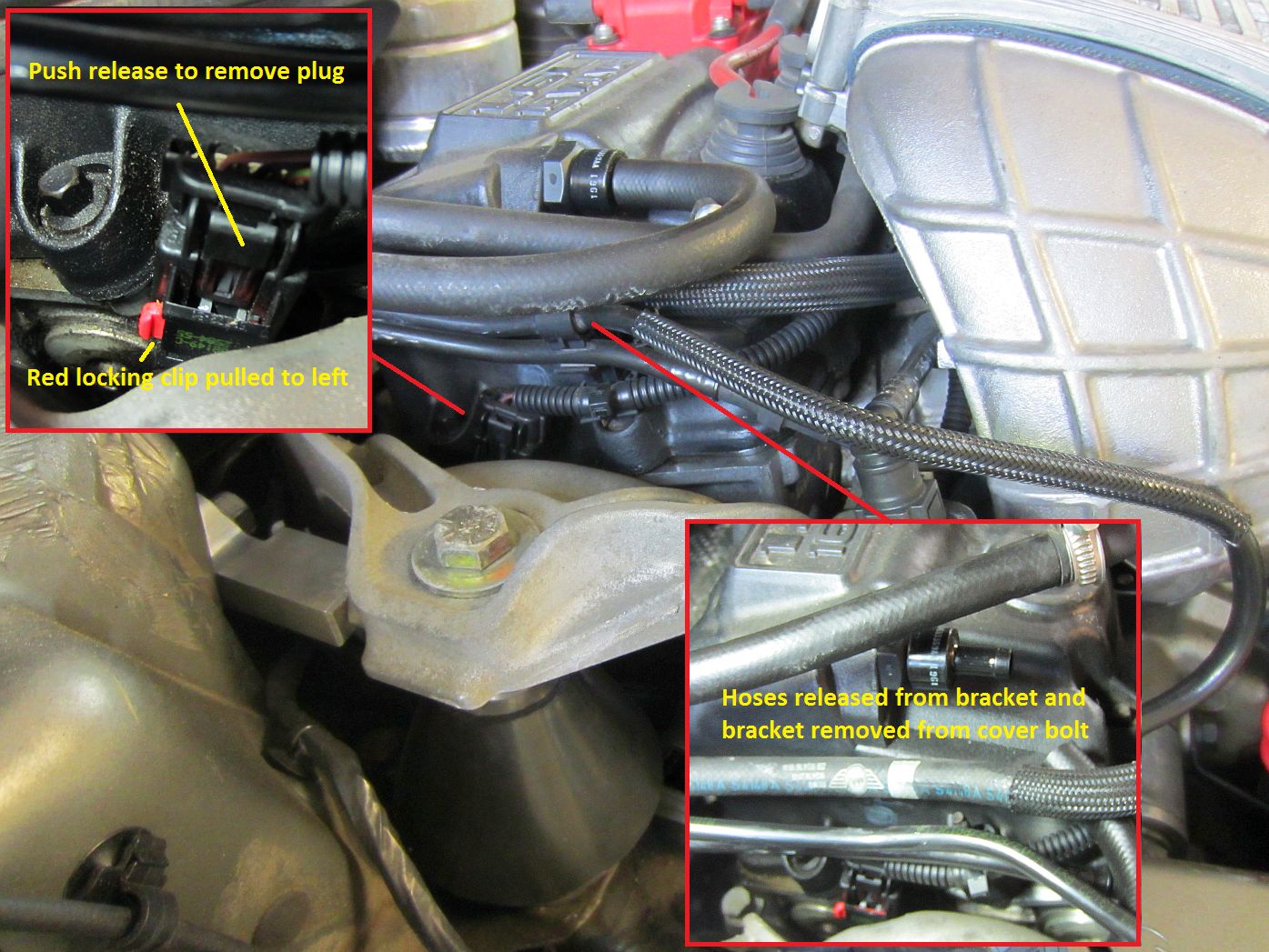
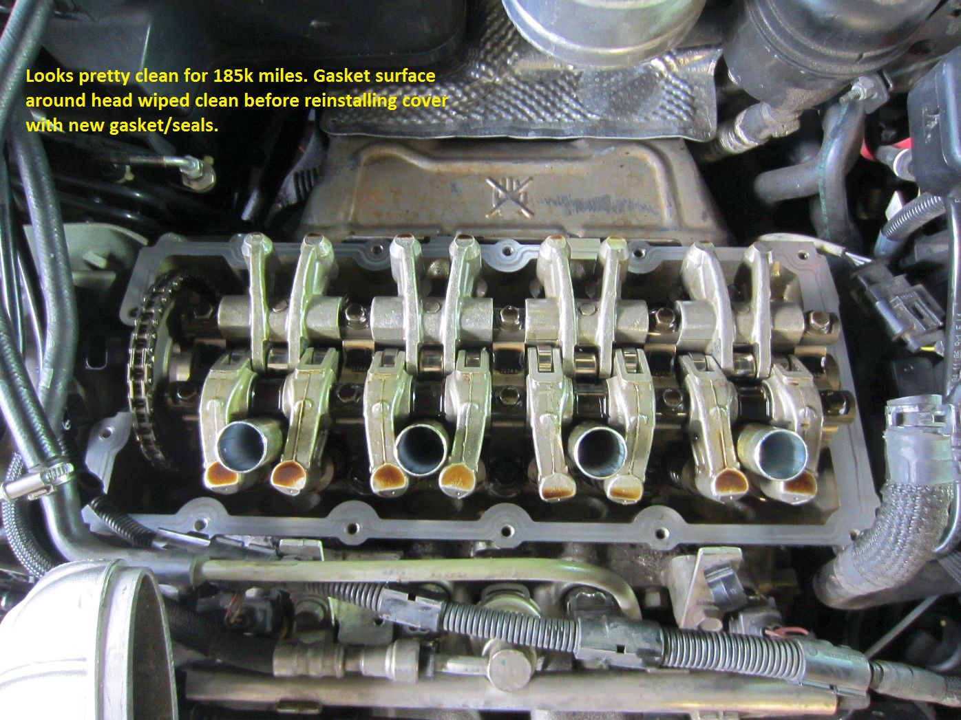
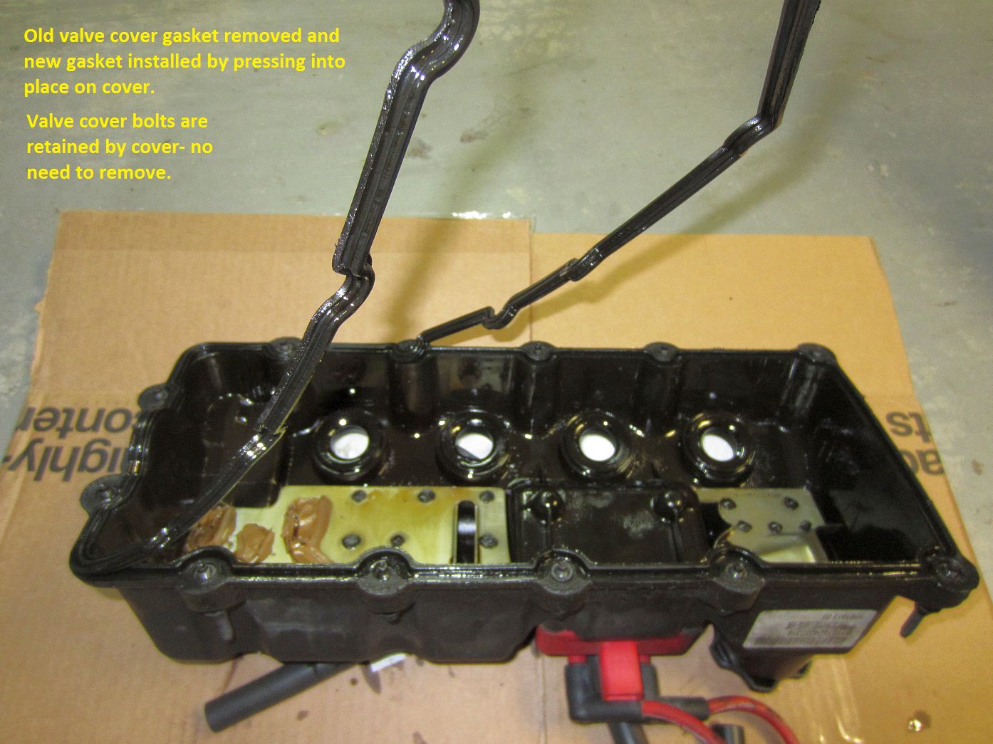
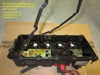
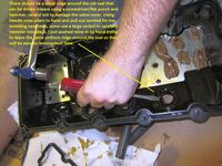
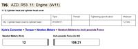
The Mini needed some TLC at ~185k miles so at this oil change I decided to go ahead and replace the leaking valve cover gasket, pre-emptively replace the spark plug tube seals, and track down my boost gauge issue- gasket/seals purchased from my friend Way at Way Motor Works. I have some pics below to illustrate the process. I started by removing the intercooler, not removing the boots from the intercooler but loosening all of the clamp bolts and pulling off the intake horns. Next, all spark plug boots are pulled and placed out of the way. Two plugs need to be unplugged, one at the coil and one on the passenger side of the motor- slide the red clip to the left side of the plug and push release to unplug. Several hoses in a clamp need to be released, and the clamps and wire retainers removed from the valve cover bolts. The PCV and breather hoses are removed and then the two intercooler brackets. Now, all that needs to be loosened completely (but not removed, they are retained in the cover) are the valve cover bolts, front/back/passenger side. A little tug up on the valve cover should break it free from the spark plug tubes- I did NOT remove the coil from the cover or the spark plugs from the motor, no real need and just adds time and possible error to the process. With valve cover removed, the old gasket is pulled out and the new one pressed into place. The spark plug tube seals can be removed using a flat screw driver/punch and hammer to hammer the seal inward (don't damage the valve cover) and then removed with some needle nose pliers while twisting and pulling. Valve cover reinstalled and bolts gradually tightened from inside to outside alternating front/back to 12NM (~106 in-lbs). Boost gauge turned out to be the reducer Autometer supplies, it does not seem resistant to heat/aging and was dried/cracked- I replaced it with some silicone vacuum line that was cinched tight to the plastic line with small zip ties and pushed tightly on to the T fitting. ALL works
Now I guess I get to plan for the oil pan gasket replacement......
Some resources I used to do this were Pelican and the NAM Forum.
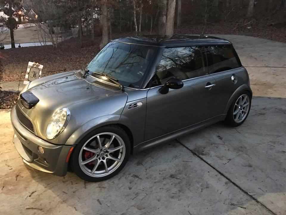
At 185,500 miles and almost 7 years of ownership we decided to sell our Mini to other friends that are also enthusiasts. It was a great car and currently holds the record at my house for both length of time owned and miles accumulated. Below is a pic the night it was sold, taken by the new owners:
DIY Guides:
Pelican Parts: Mini Cooper Technical Articles INDEX
BillsWebSpace: MCS Pulley/Upper Motor Mount/Tensioner Stop/Tensioner Damper Bushings DIY Guide
BillsWebSpace: Mini Cooper S (R53) BSH Lower Mount Installation Guide
BillsWebSpace: Mini Cooper S (R53) MSD Coil and MagnaCor Wires Installation
BillsWebSpace: Mini Cooper S (R53) Alta Intercooler and Intake Silicone Hoses Installation
BillsWebSpace: Mini Cooper (R50-R53) Power Steering Pump/Fan/Duct DIY Guide
BillsWebSpace: Mini Cooper Cabrio Brace Installation
BillsWebSpace: Mini Cooper Shifter/Brake Boots Installation and Shortened Shifter
BillsWebSpace: Mini Cooper JCW Steering Wheel Installation
BillsWebSpace: Mini Cooper JCW Brake Handle Installation
BillsWebSpace: Mini Cooper S (R53) DDM Cold Air Intake Installation
BillsWebSpace: Mini Cooper (R50/R53) Hotchkis Camber Plate Installation
BillsWebSpace: Mini Cooper S (R53) Mini Madness Rear Sway Bar Installation
BillsWebSpace: Mini Cooper (R53) Mini Madness Lower Brace Installation
BillsWebSpace: Mini Cooper (R53) Powerflex Manual Transmission Bushing Inserts Installation
BillsWebSpace: Mini Cooper (R50/53) Powerflex Rear Trailing Arm Bushing Inserts Installation
BillsWebSpace: Mini Cooper S (R53) GTT Lower Mid Brace Installation
BillsWebSpace: Mini Cooper S (R53) GTT Aerobox Strutbrace Installation
BillsWebSpace: Mini Cooper S (R53) Radar Detector Hardwire Guide
BillsWebSpace: Mini Cooper (R50-53) TSW Billet Jack Points Installation
BillsWebSpace: Mini Cooper (R53) Forge Coolant Tank/Reservoir Installation
BillsWebSpace: Mini Cooper (R53) BSH Catch Can Installation Alternative for OE Alarm Owners
BillsWebSpace: Mini Cooper S (R53) Engine Oil Change Guide
BillsWebSpace: Mini Cooper/S (R50/53) Fuel Filter Replacement Guide
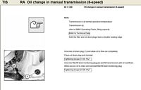
BillsWebSpace: Mini Cooper S (R53) Transmission Oil Change Guide
BillsWebSpace: Mini Cooper S (R53) JCW Front Brake Pads and Rotors DIY Guide
BillsWebSpace: Mini Cooper S (R53) Header Installation
BillsWebSpace: Mini Cooper S (R53) Valve Cover Gasket Replacement
BillsWebSpace: Mini Cooper S (R53) Apex Springs and Hotchkis Adjustable Camber Links Installation
BillsWebSpace: Mini Cooper S (R50/53) OE Alarm Retrofit Installation
BillsWebSpace: Mini Cooper S (R53) Boost/Oil Pressure Gauges DIY Guide
BillsWebSpace: Mini Cooper S (R50/53) Kuda Mount and Phone Micro-USB Power Cord Hardwire
CravenSpeed SC Pulley Replacement Guide
Alta Performance SC Pulley Replacement Guide
KAV S Motorsport SC Pulley Replacement Guide
Mini Mania SC Pulley Replacement Guide
Terry Sayther Automotive SC Pulley Replacement Guide
Mini-Madness Rear Sway Bar Installation
Hotchkis Sway Bar Installation
Alta Rear Sway Bar Installation
Mini Mania Rear Sway Bar Installation
Mini Cooper Lowering Removing Sub-Frame R50-R53
Mini Cooper 2005-2006 R50-R53 Dash Top Removal
Bentley Wiki: 2002-2006 Mini Cooper S Supercharger Oil Service
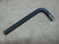
agranger's Guide to R53 Belt Replacement
agranger's Guide to R53 Supercharger Oil Service
agranger's Guide to R53 Crank Sensor Seal Replacement (pdf version HERE)
Applesauce's Guide to Valve Cover Gasket Replacement
Mod MINI's Guide to Replace MINI Cooper crank sensor o-ring & oil pan gasket R50 R52 R53
Reviews:
Related Documents/Pics/Files/Links:
Real OEM: OEM Part Numbers and Diagrams Online
2005 Mini Cooper Owners Manual
Unauthorized Mini Cooper Owners Manual
Video: *High Speed Connection Recommended*
FCP Euro: Built R53 MINI W11 Engine Teardown - What Happens If A Fuel Injector Fails
Mini Cooper Forums/Links: