

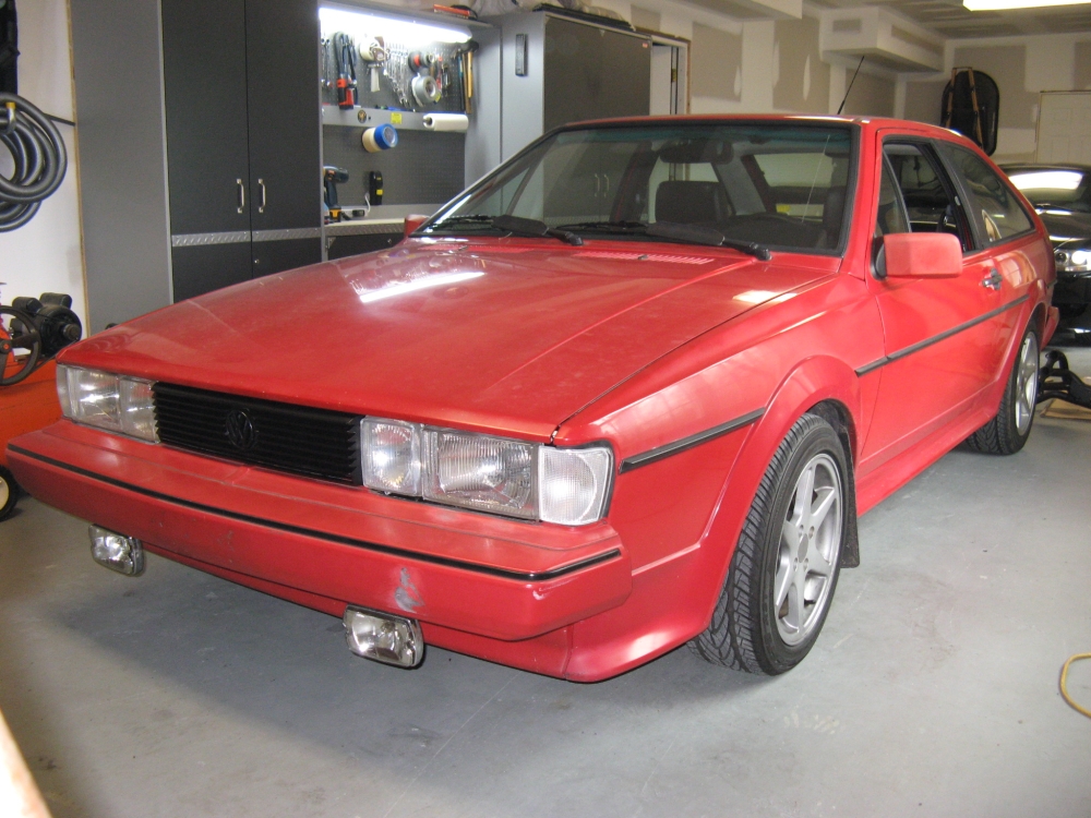
Click on thumbnails below for larger pics....
This car was purchased from the third owner who only put a few thousand miles on it in the course of ~3 years. My friend, the second owner, turned me on to
this car when he knew I was looking for something for my daughter to learn to drive in. Prior to selling the car to the third owner he had used the car as
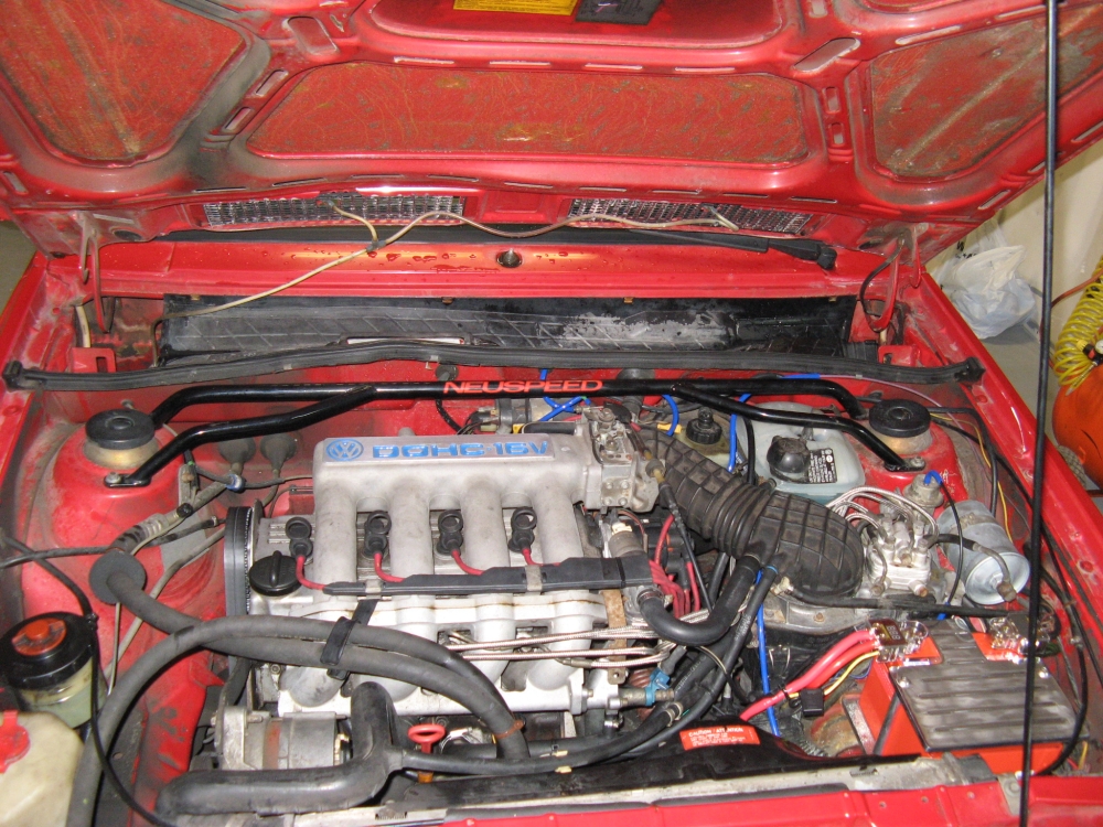
a daily driver and occasional track rat so the car had aftermarket suspension
(Neuspeed Sport Springs and
Tokico Illumina dampers with poly strut bushings), front
Neuspeed Front Upper Strut Tie-Bar/OE lower brace,
and Cibie H4 outer lights and driving lights.
He had also replaced all of the hoses, brakes (rotors/pads), clutch/clutch cable, and belts to make sure it would be reliable for the friend he was selling it to.
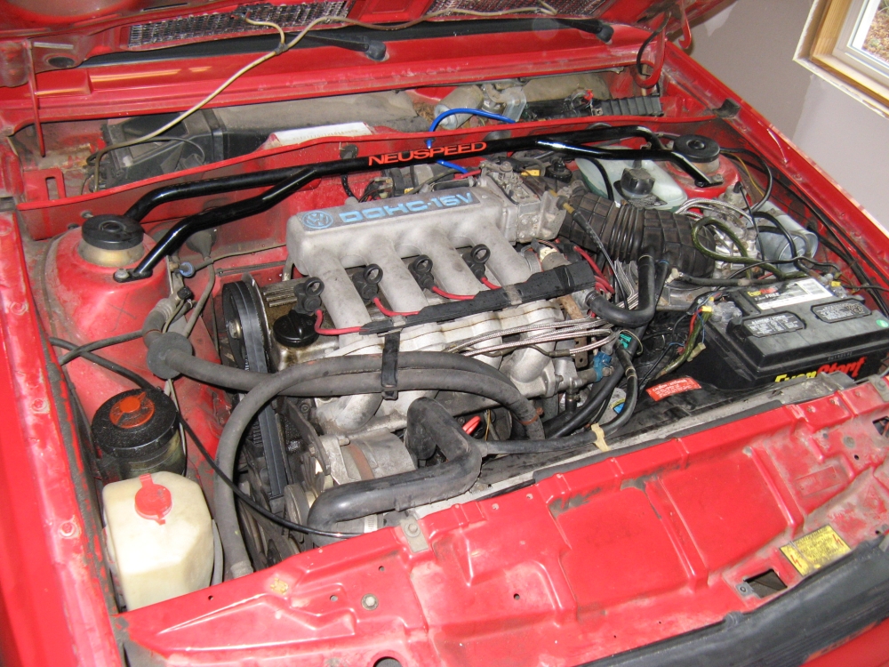
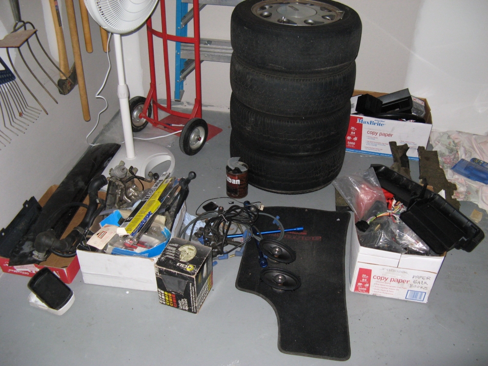
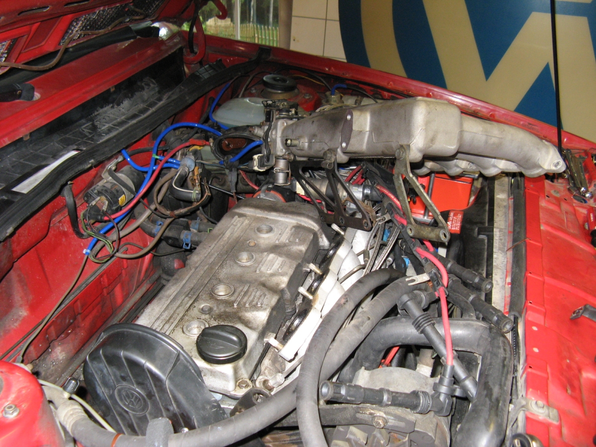
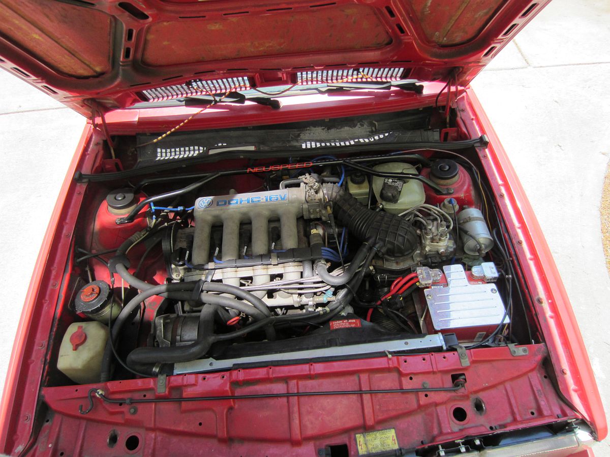
The car ran on two cylinders on the way home but was in good cosmetic/mechanical shape considering. Visually, we knew that there were several vacuum lines
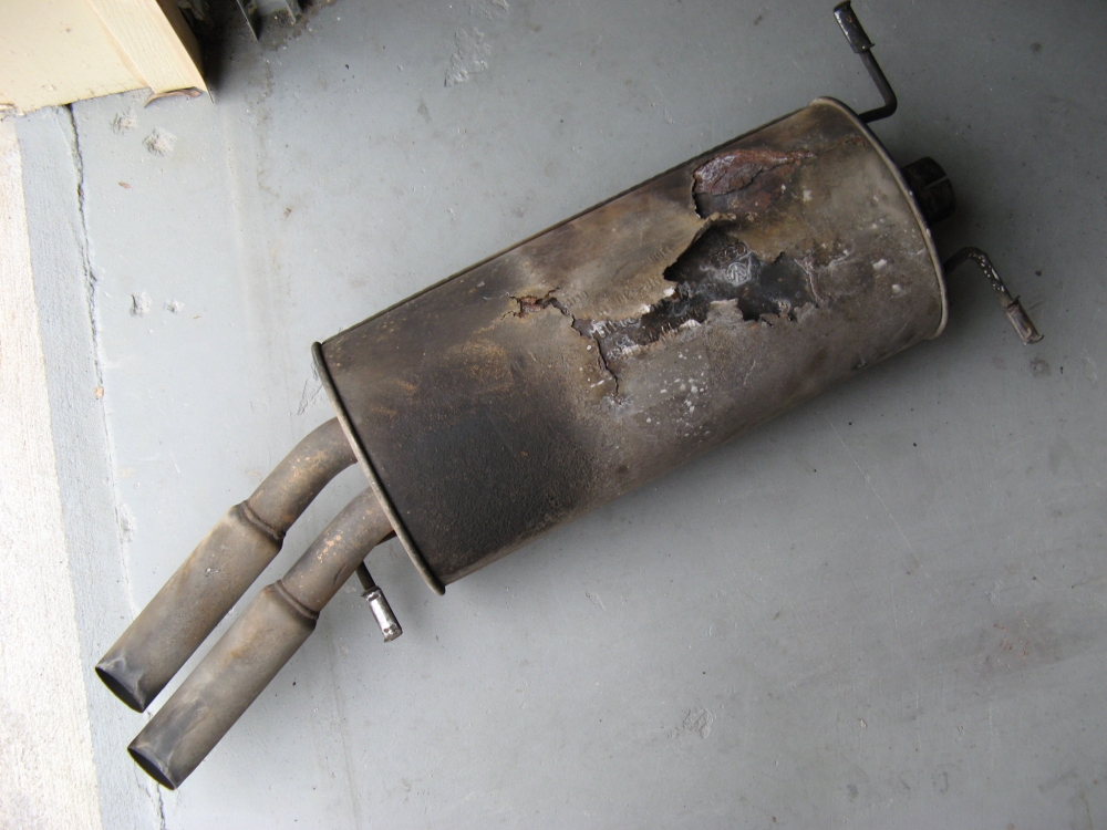
that needed to be replaced, a small tear in the intake boot, torn EGR hose, loose and disconnected wires, and a rusty muffler. The prior owner had spent significant $$$ with
reputable Sarasota shops/mechanics (email me for more info) prior to meeting us but they had failed to resolve the poor run condition. The poor running condition was diagnosed by us as incorrect order of the
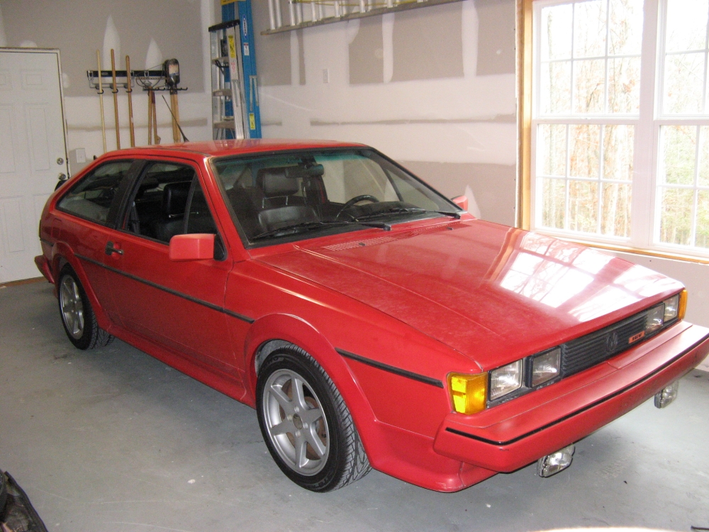
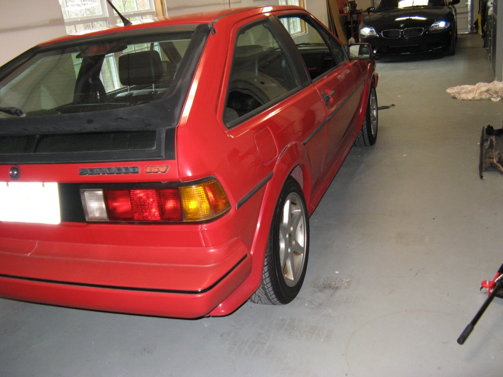
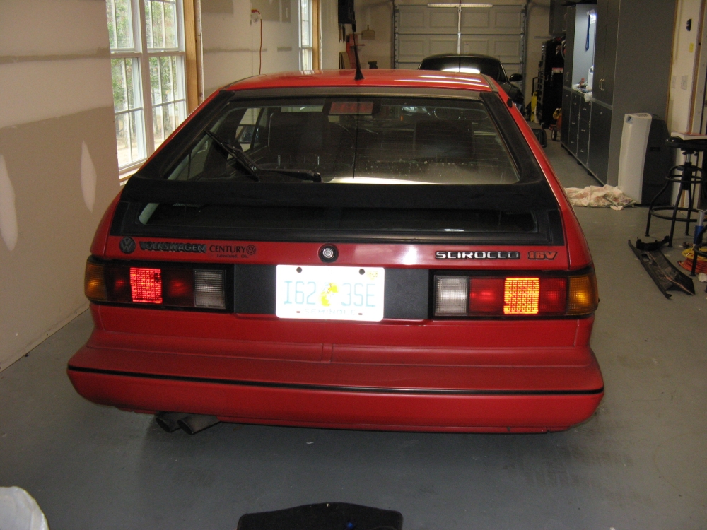
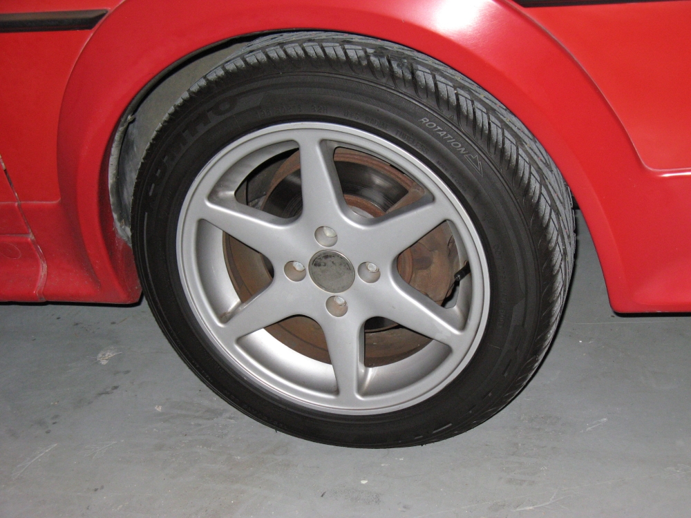
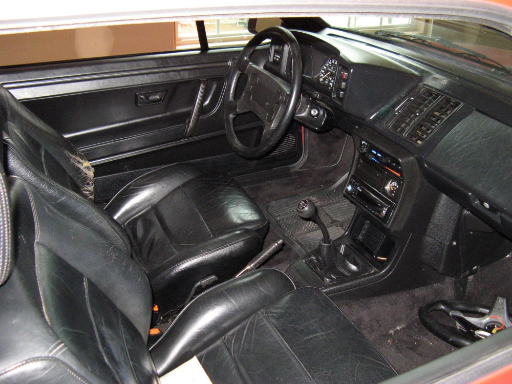
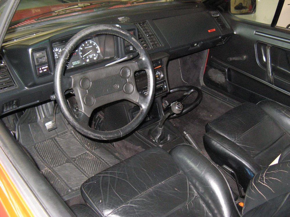
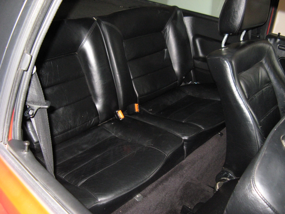
spark plug wires on the cap. Here are some pics the day I got it home, it came with a lot of spare parts
as well (including the OE teardrop Wheels), in the pics below the rain tray and upper timing belt cover had been removed and one new vacuum line to the knock sensor
control installed.
The first thing addressed was the order of the wires on the cap (should be 1>3>4>2, diagram HERE
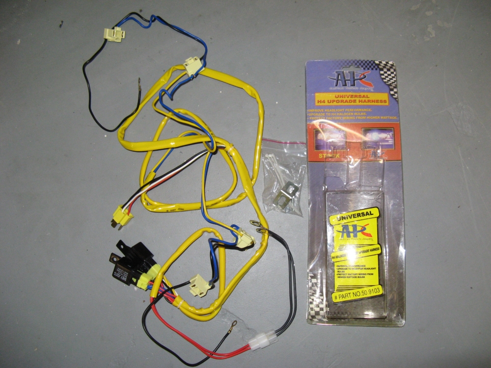
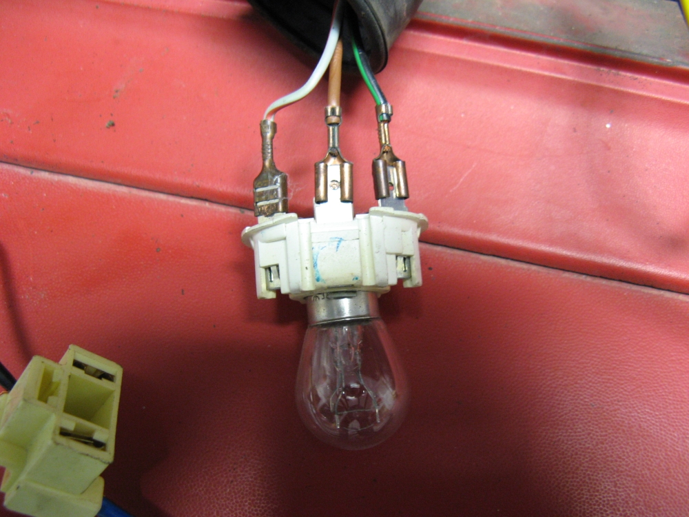
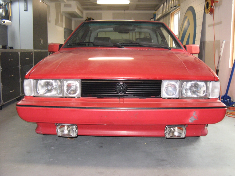
Euro lights sourced from VW Vortex classifieds along with new clear euro turn signals. I found a new old stock/no longer available APC H4 relay wiring harness on eBay for $3 ($13 shipped
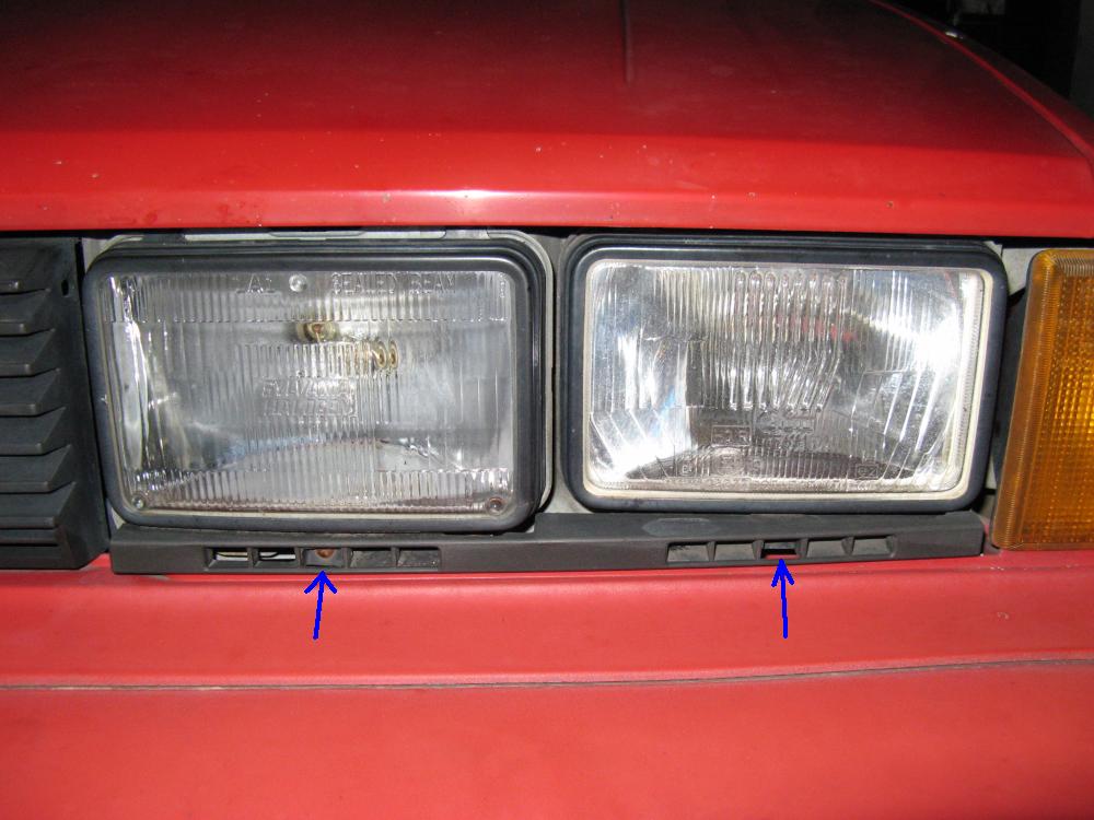
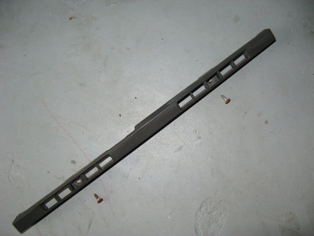
The OE headlights are removed by first removing the two screws holding the lower trim strip in place, then the 5 screws holding the headlight assembly in place are removed.
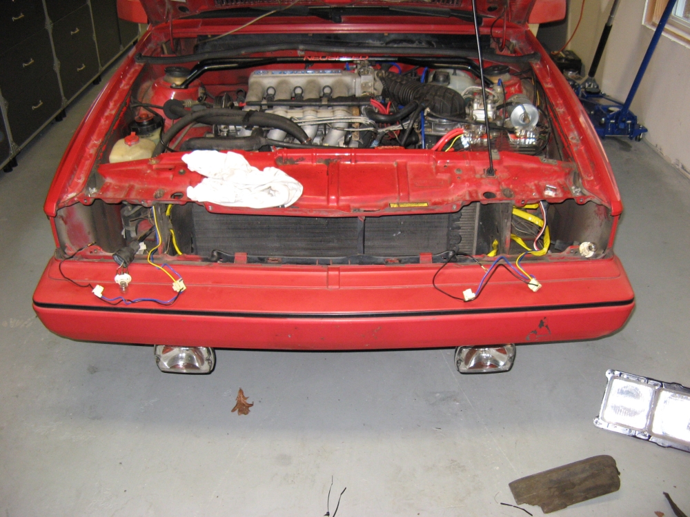
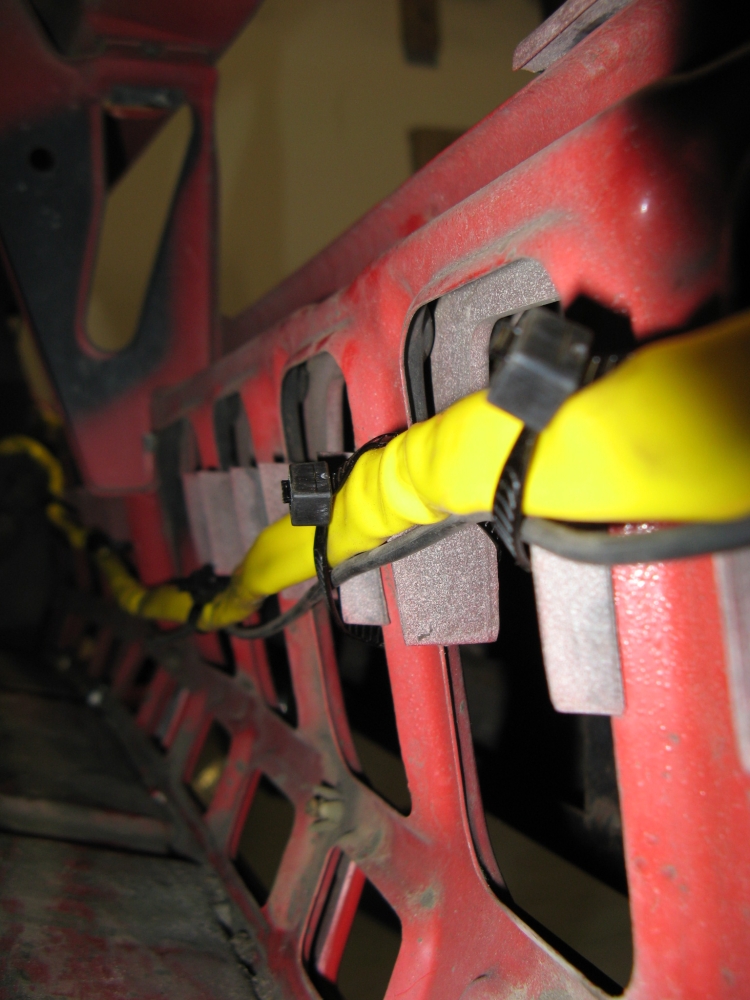
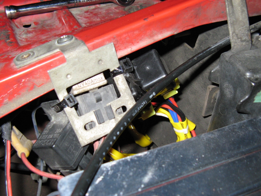
Removing the center grill makes running the wiring harness a little easier, wire harness is zip-tied to the front of the body. Wiring harness relay trigger wires are plugged
into the OE headlight harness on the driver's side (after pins are swapped to be correct), 12v+ wires to relays are fused and connected, and ground holes are drilled on either
side of the car and screws secure them to the chassis (bare paint visible should be painted over to prevent rust). The aforementioned wiring harness modifications are made and
connected to headlights to test. The relays have been zip tied out of the way until a permanent mounting solution is in place.
The upper screw holes all line up but the bottom two screw inserts need to be moved down to the other hole (arrows in PIC) to line up. I found that it was easier to modify the lights
than to modify the bumper trim, I had to grind 1/8" to 1/4" down on the top/bottom (mostly bottom) of the headlight plate to clear the bumper. I also ground down the high beam
frame at the bottom to allow it to clear. By removing the plastic lip on the bumper trim with a Dremel I could access the mounting bolts and adjusters easily, it will get painted when I paint the car.
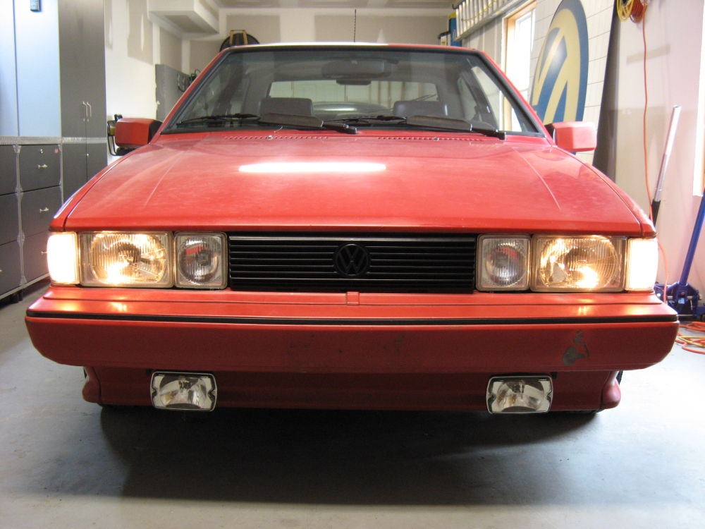
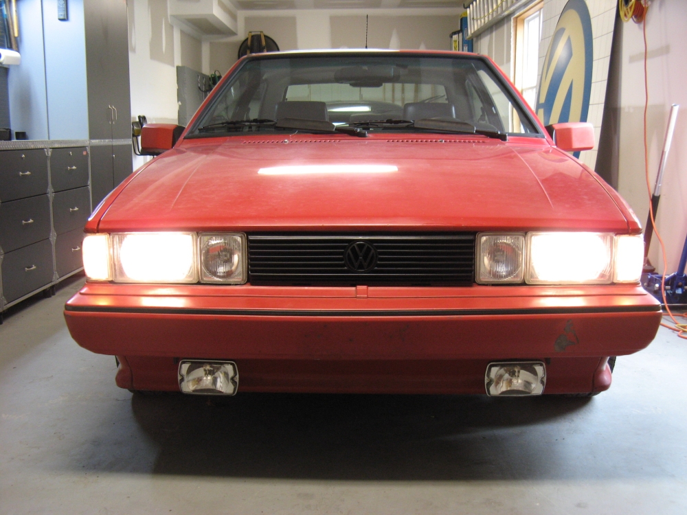
The euro lights are aesthetically better than US DOT spec and provide a lot of light where needed.
Some helpful links for me were the Scirocco.org Eurolight DIY Guide and
Timbo's Write-Up on Headlight Relays/Wiring.
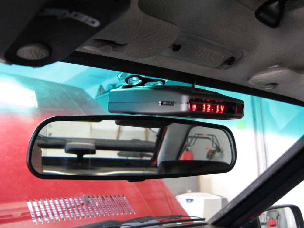
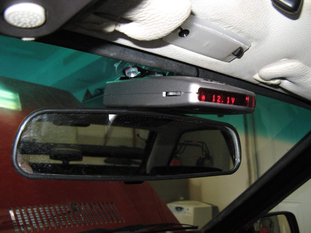
Passport 8500 X50 (manual HERE)
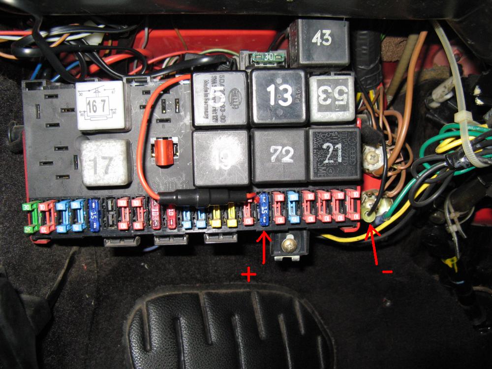
hard wired, functions as voltage guage between alerts, not easily noticed looking
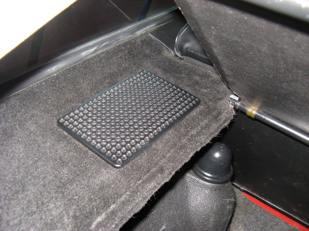
in from outside. Wire was tucked under the rubber window seal and run down to the fusebox. Ignition 12v+ was tapped on the number 16 (Horn) Fuse which only sees power when the car is on,
VW has a ground terminal next to the fuse box which was used for 12v- after a spade terminal was crimped to the ground wire:
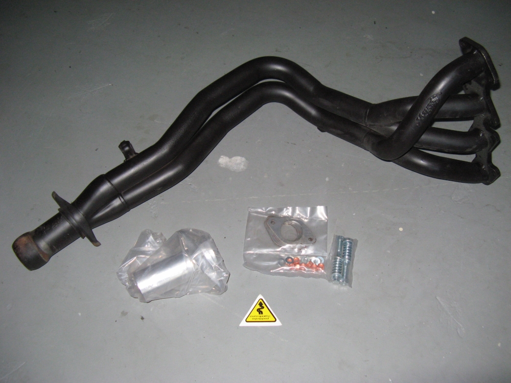
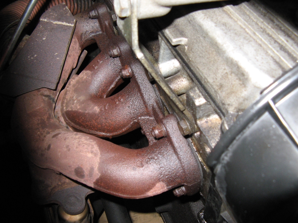
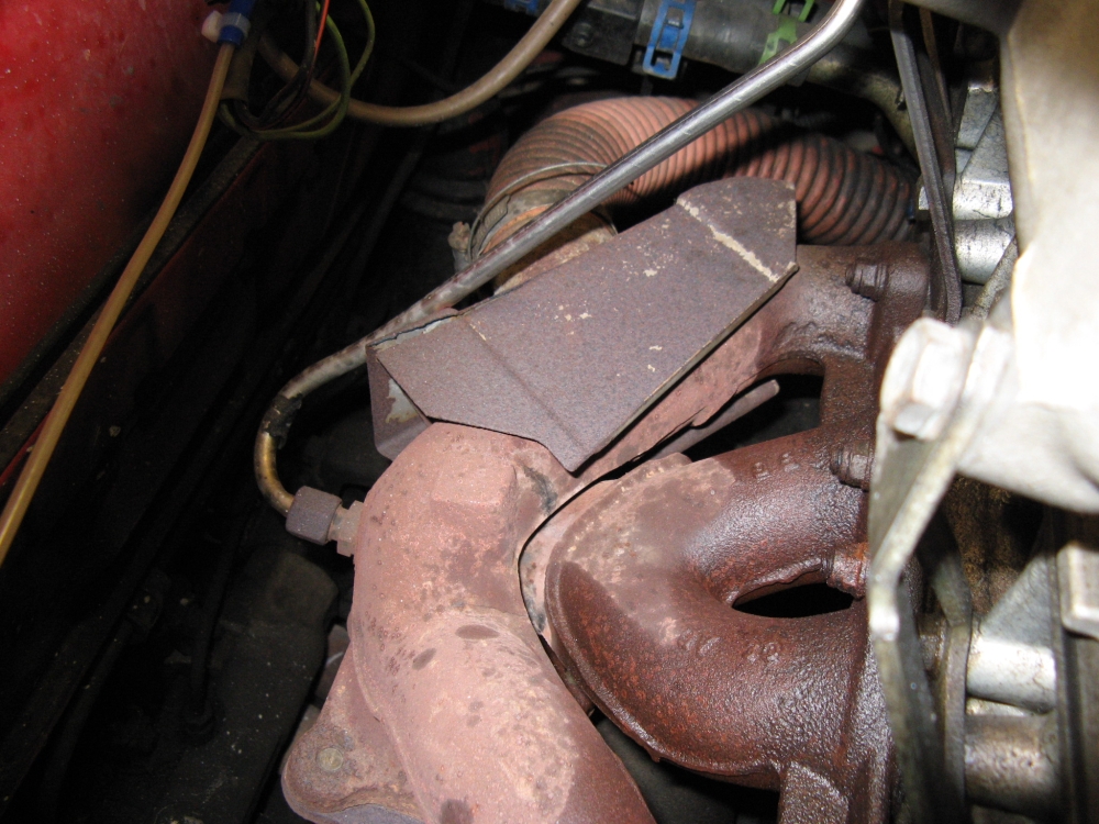
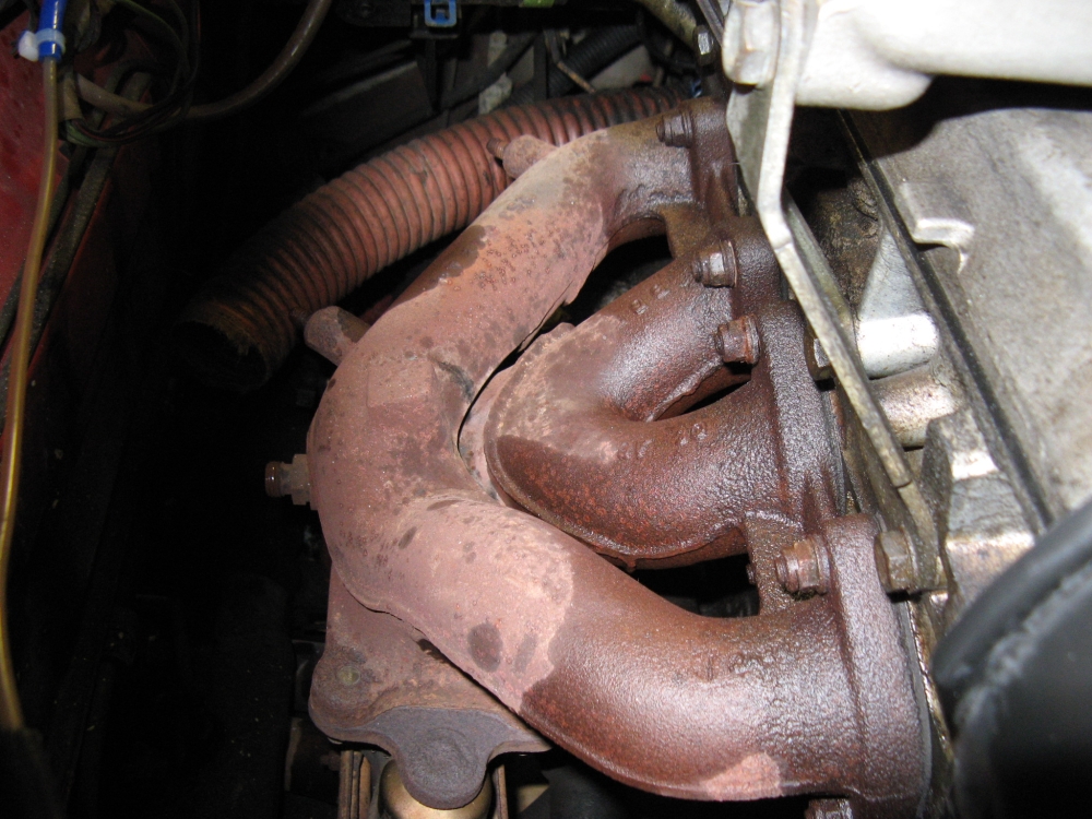
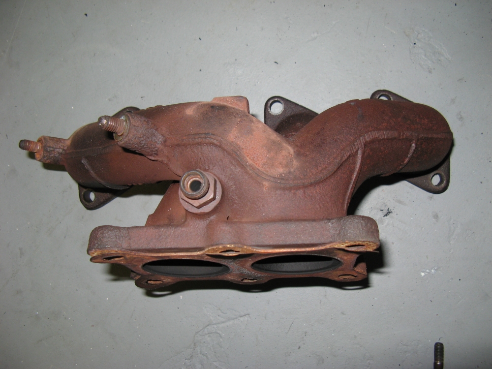
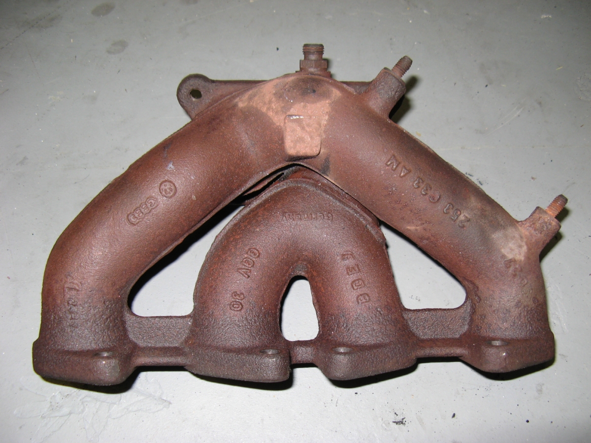
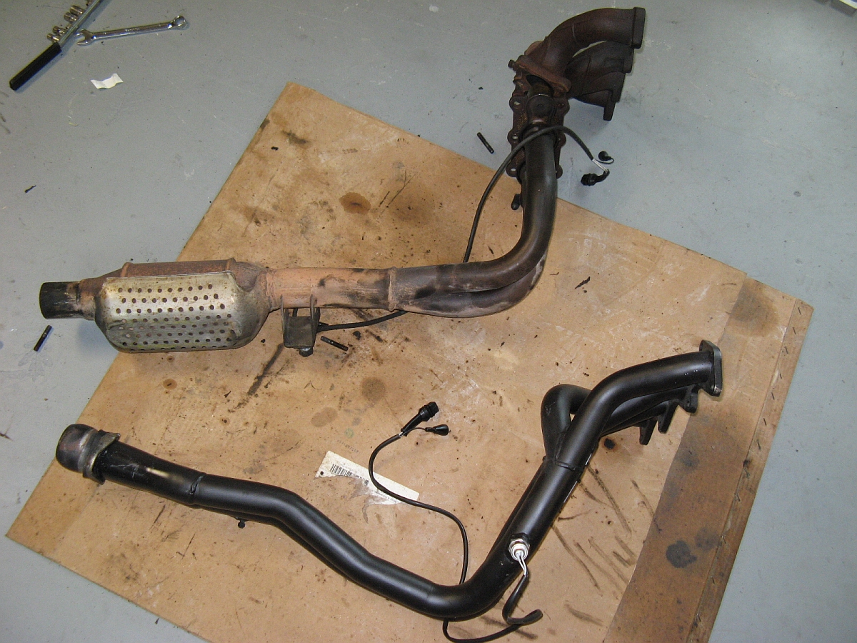
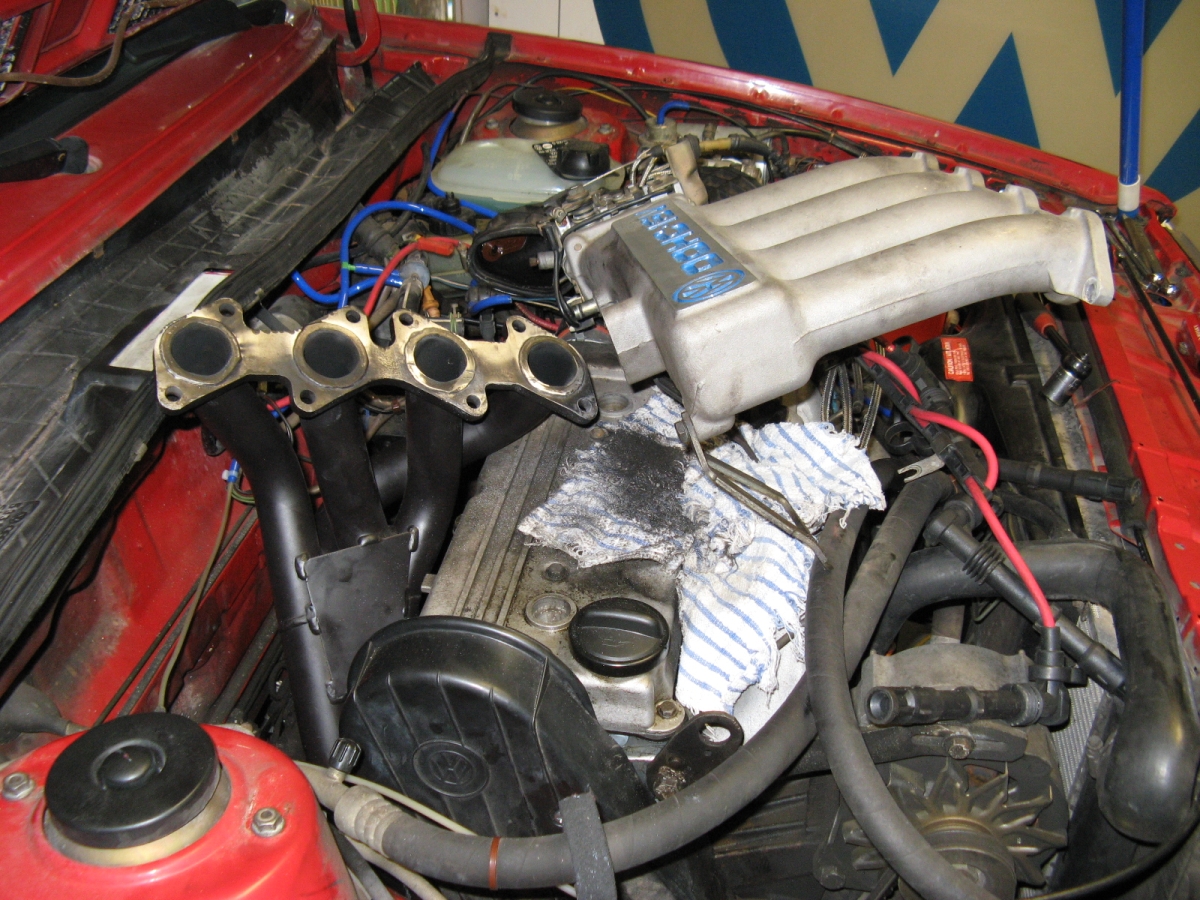
Pre-owned Euro Sport Accessories header found in Vortex classifieds and new hardware
purchased. It only made sense as the OE exhaust manifold was cracked in several places and the cat was most likely bad/going bad......
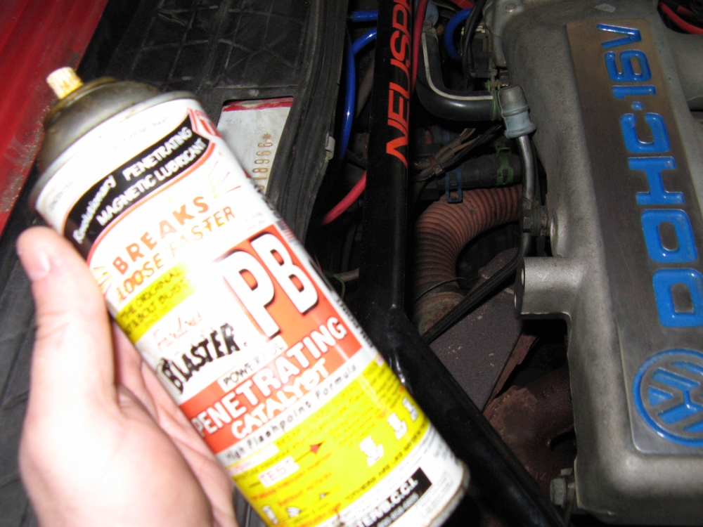
and I was planning to replace the exhaust as well. I started by liberally soaking all of the old exhaust manifold/downpipe studs and bolts with PB Blaster, 20 years
of heat cycles/moisture tends to rust things a bit and make bolts hard to remove. Some were so bad that the wrench wrung the heads off and these were removed with
ViceGrips.
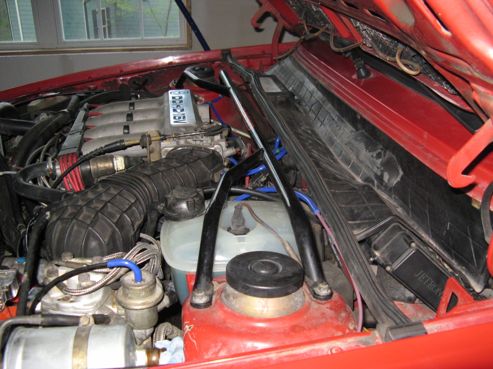
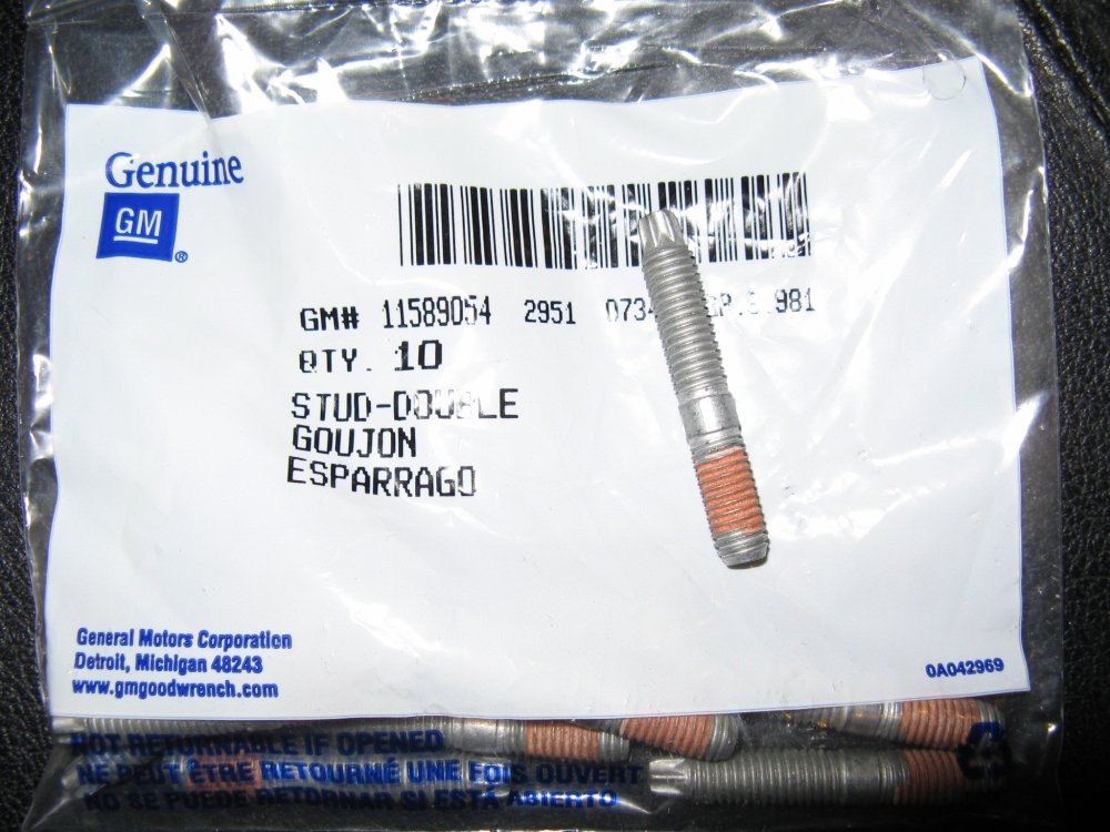
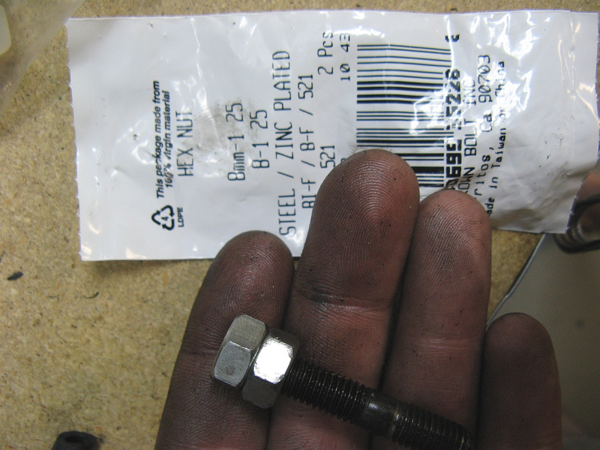
The upper brace was removed while the car was on the ground, two nuts per side, and the nuts replaced on the strut mount bolts.The heater pipe for the intake was removed and then the air tube and heater pipe box were removed. I sourced new Saturn exhaust manifold studs to replace mine from
the local Saturn of Gwinnett parts department but they can also be sourced online a little cheaper
at GM Parts Direct, GM P/N 11589054- these studs are reputed to be a little
stronger and have E6 external Torx heads to install/remove, threadlock on head side, and are M8 x 1.25 (Bentley torque spec for the nuts is 25 Nm or 18 ft/lbs).
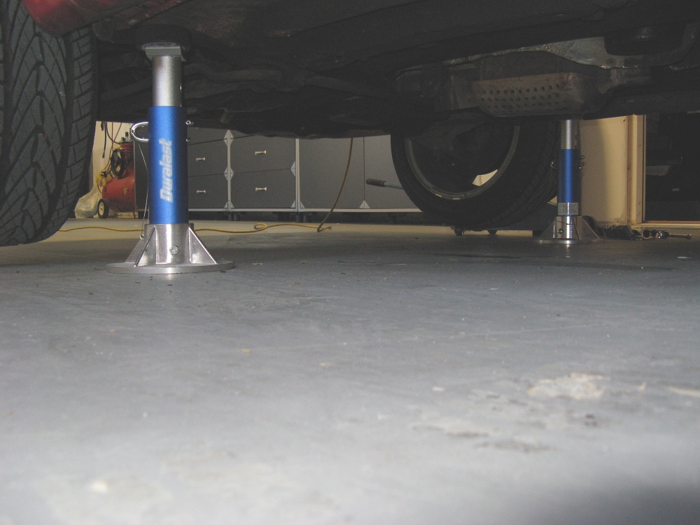
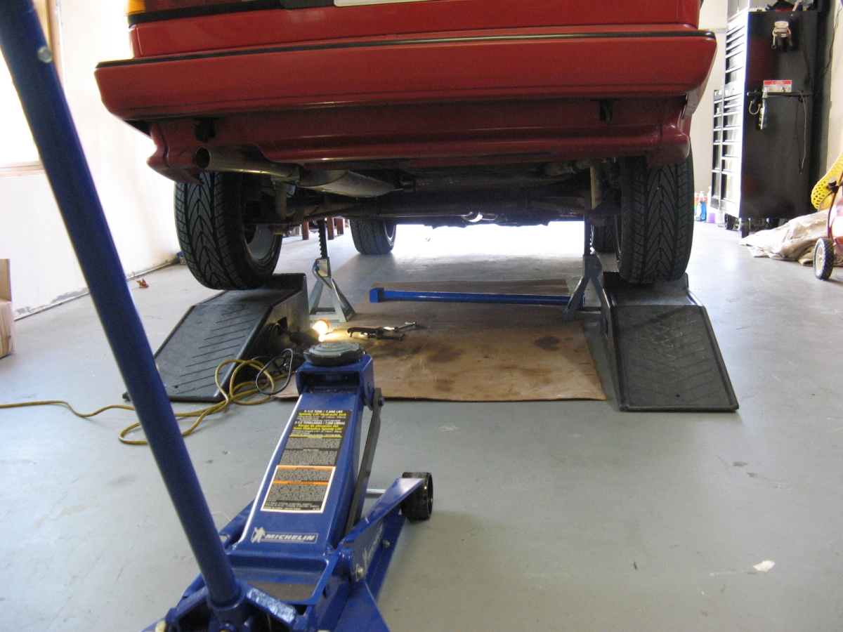
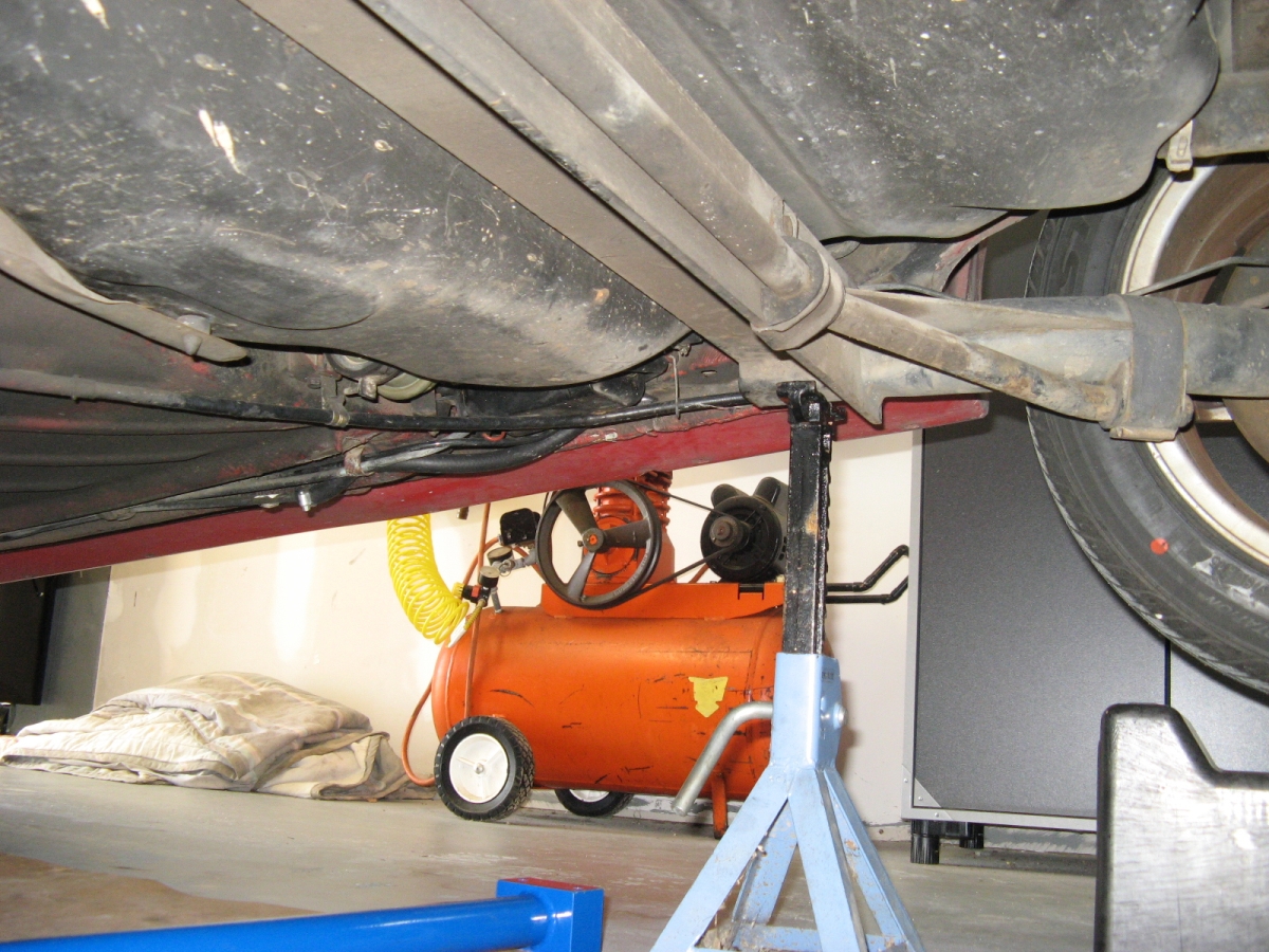
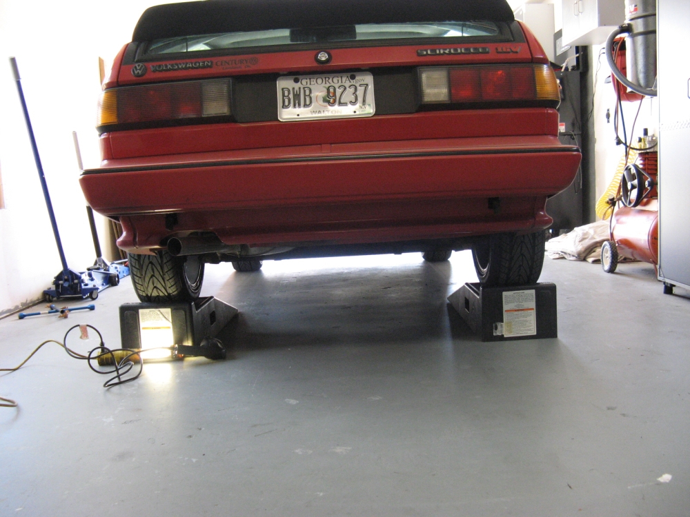
The car was raised by jacking at the front pinch rail jack point and placing a jack stand (with hockey
puck as jack pad) under the front lift jack point and another jackstand at the rear pinch rail jack point (hockey puck with routed area for pinch rail
as a jack pad).
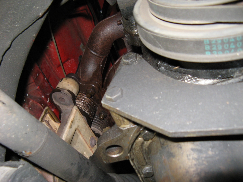
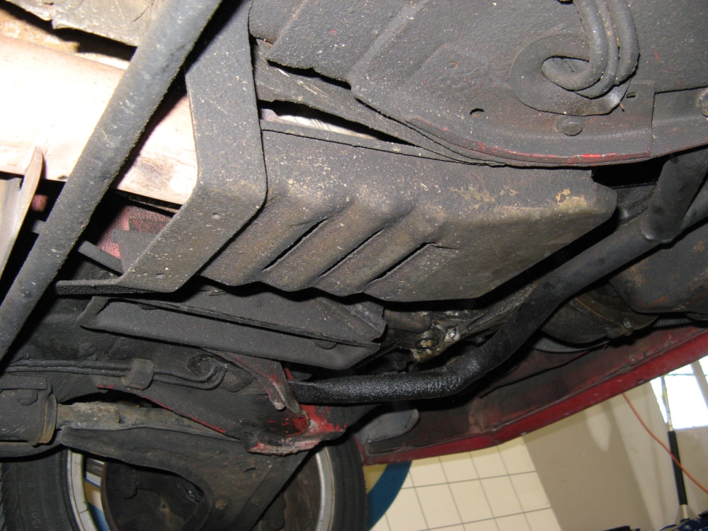
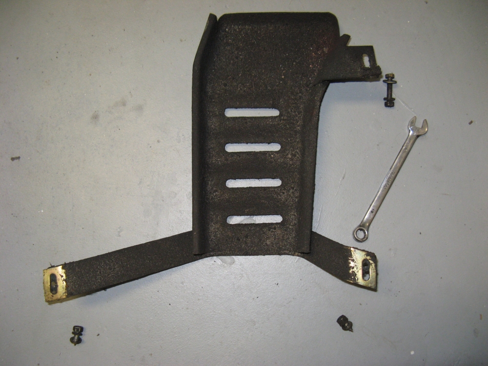
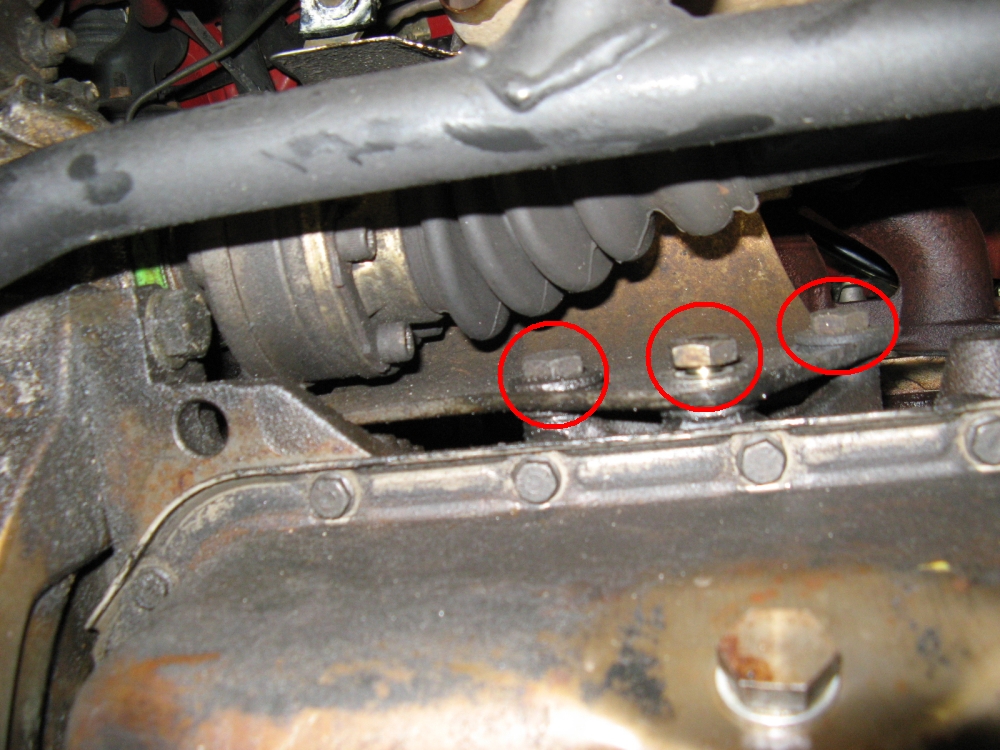
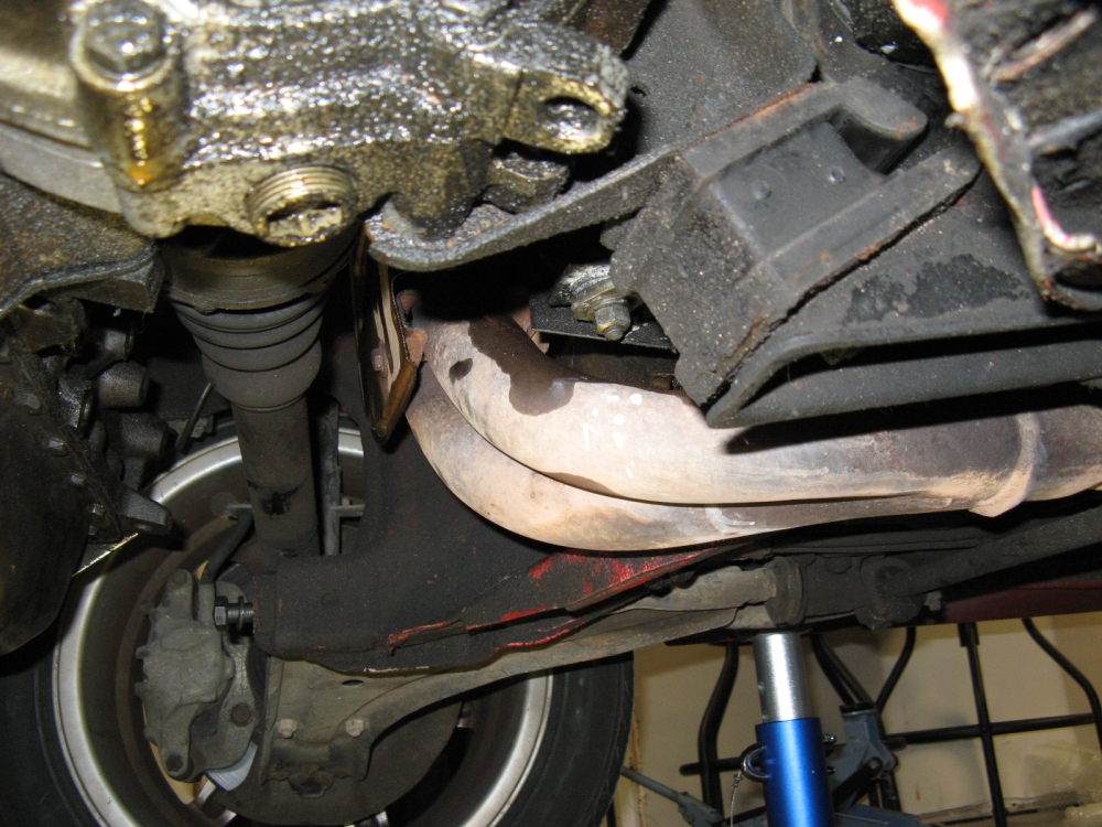
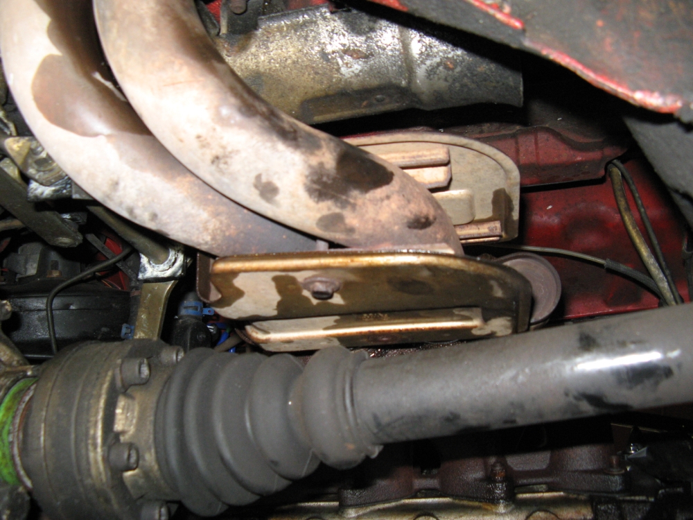
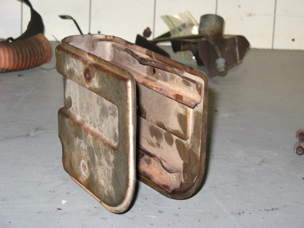
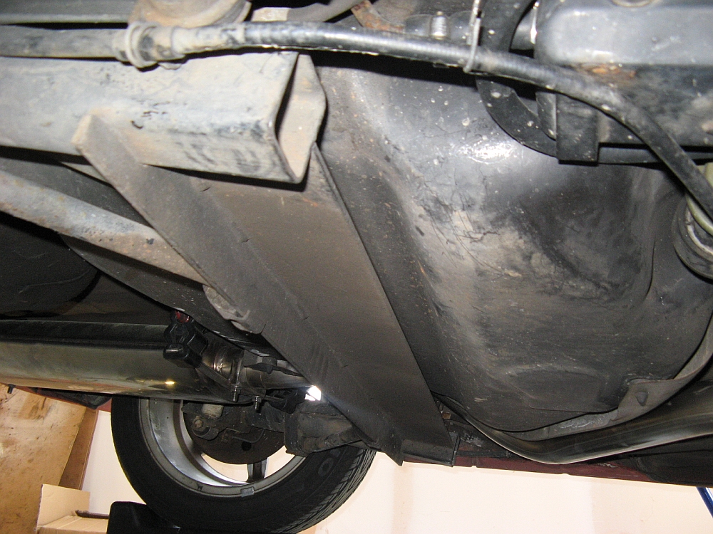
The rear muffler was removed and then the center pipe with resonator was removed. The next item for removal was the front lower heat shield/guard. Three bolts
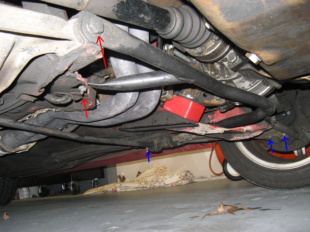
holding the driveshaft heat shield on (circled) were removed and the heat shield was twisted around the driveshaft/lower brace and out. The lower brace and front sway bar
were removed, two bolts on each side for the lower brace (red arrows) and three nuts on each side for the front sway bar (blue arrows). The bolt removed from the
lower control arms for the brace removal was replaced and hand tightened. With these pieces out of the way, the
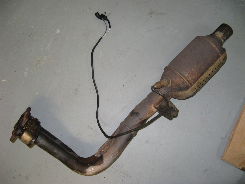
downpipe was accessible. The downpipe heatshield was removed for better access to the mounting bolts and then the downpipe was removed from under the car.
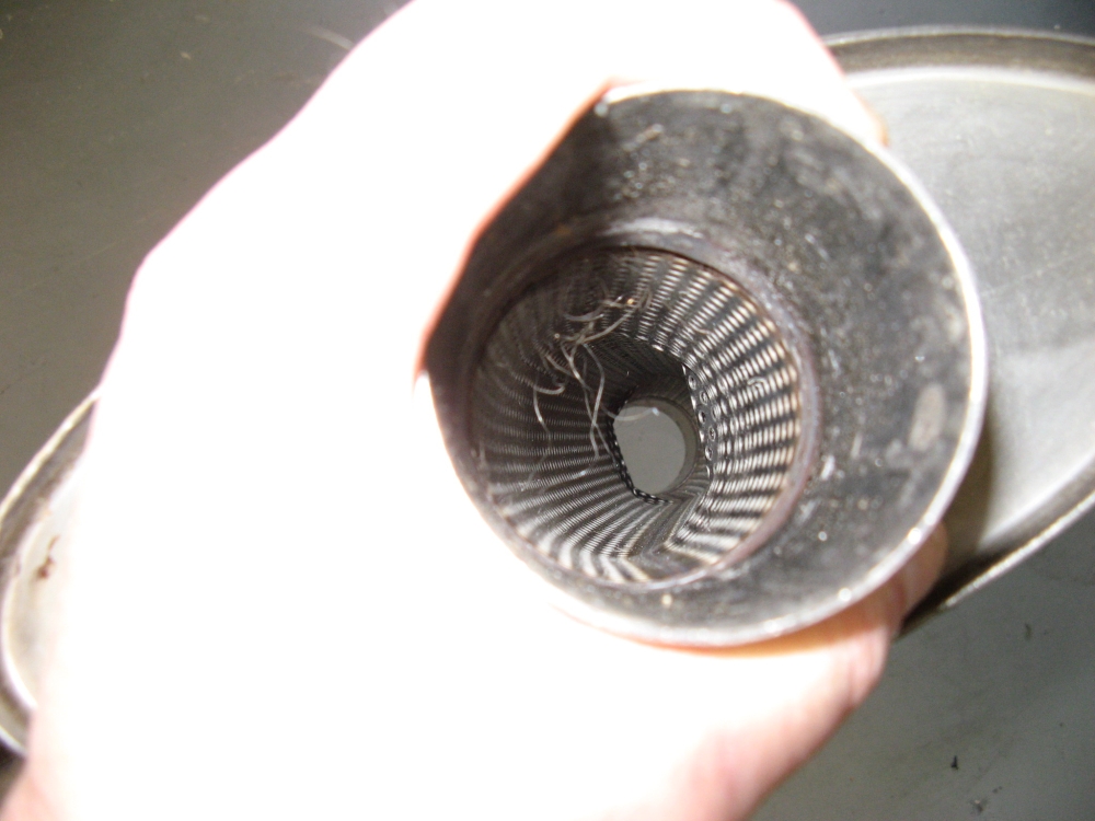
As it turned out the cat was hollow already, maybe from age or maybe human intervention?
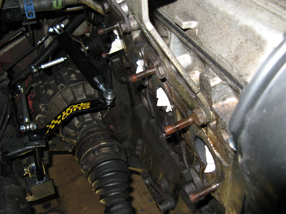
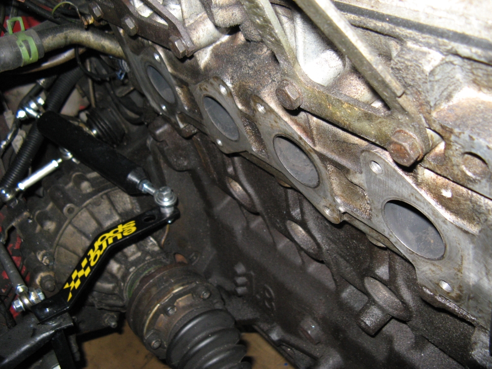
The exhaust manifold was attacked next, and attacked is the right word. Even after several applications of PB Blaster, the bolt heads were wringing off due to
rust deterioration. I was able to get all off with Vice-Grips or a socket wrench, except for one that I had to grind the nut off of the stud to remove the exhaust manifold-
trying to wedge and operate a Makita grinder in that tight space was lots of fun.....The studs were removed by using new nuts and double nutting, using a wrench to remove
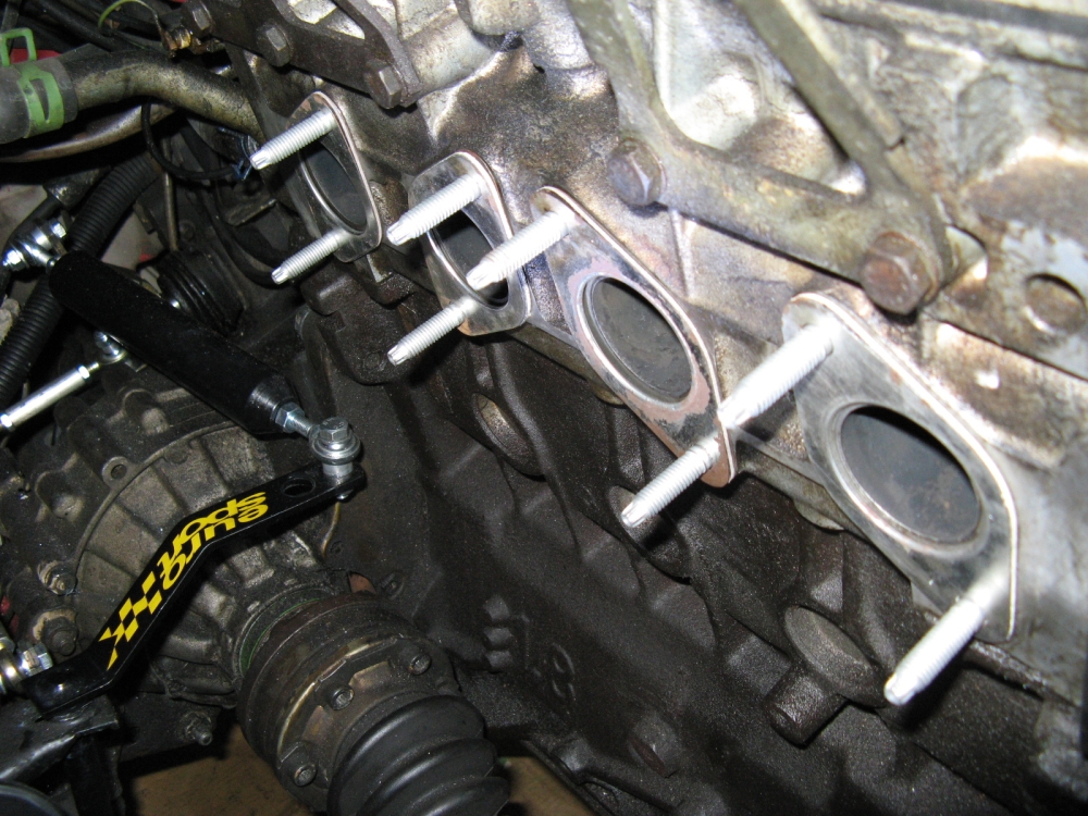
them after soaking them down with some more PB Blaster. The exhaust port surfaces were cleaned with brake cleaner. I initially installed the new studs and gaskets but
later found they would have to be installed AFTER the header was in place, not enough room to work with them in the way
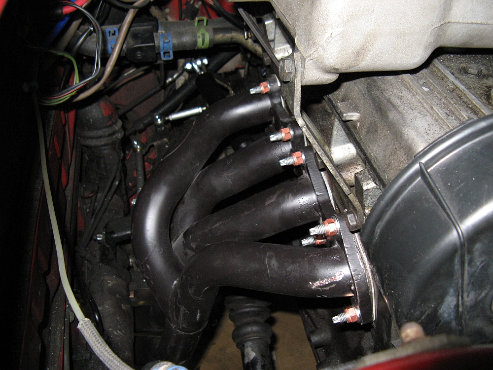
In order to install the header, I had to make room by removing the plug wires,upper intake, and associated brackets- eight nuts hold the upper to lower part of the intake manifold and the brackets attach
to the block with five bolts, don't forget to remove the nut/ground wires. The header drops in from up top, it is somewhat of a puzzle and I ended up getting out the
BFH to finish the job and a small amount of paint traded between the header and firewall. After the header was in place, the gaskets were placed between the header and
block and the studs were started. When all studs were in place and hand tightened with the external Torx socket/wrench, the new nuts were tightened in an alternating fashion,
inside to outside, until all were tightened to spec. The intake manifold was reinstalled along with the ground wires. The last piece of the header installation is to mount the connection piece
that ties the exhaust and header together.
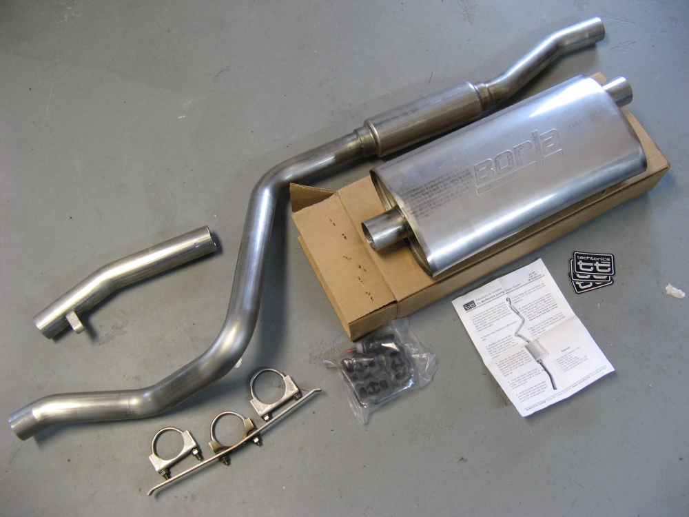
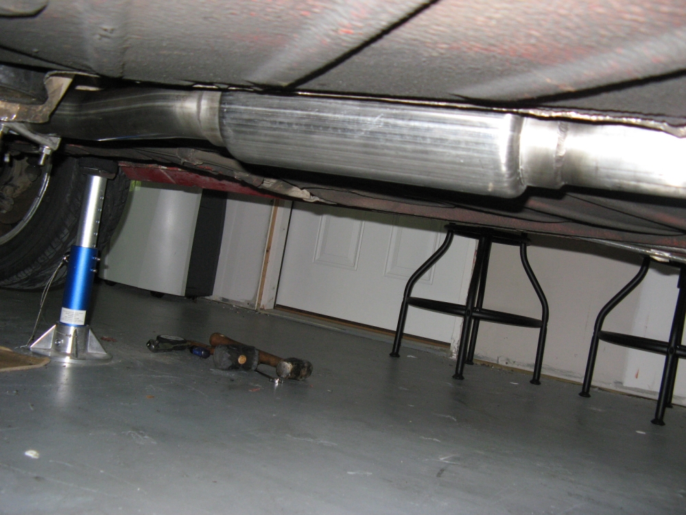
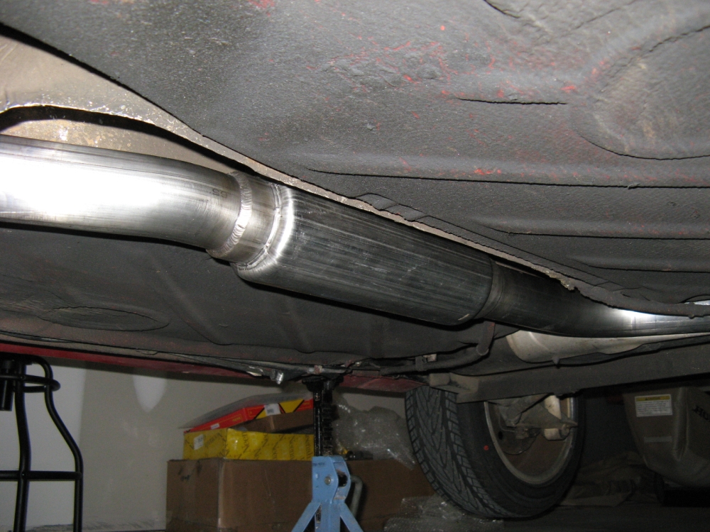
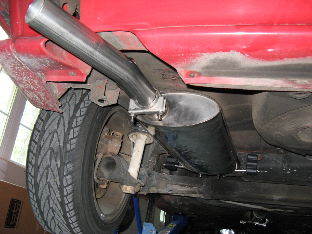
Techtonics Tuning Stainless Steel
Borla Exhaust was sourced from
German Auto Parts.com (aka Adirondack Auto Brokers, Inc.). Installation instructions
HERE.
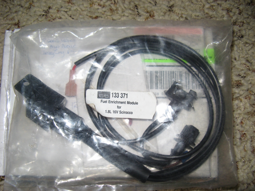
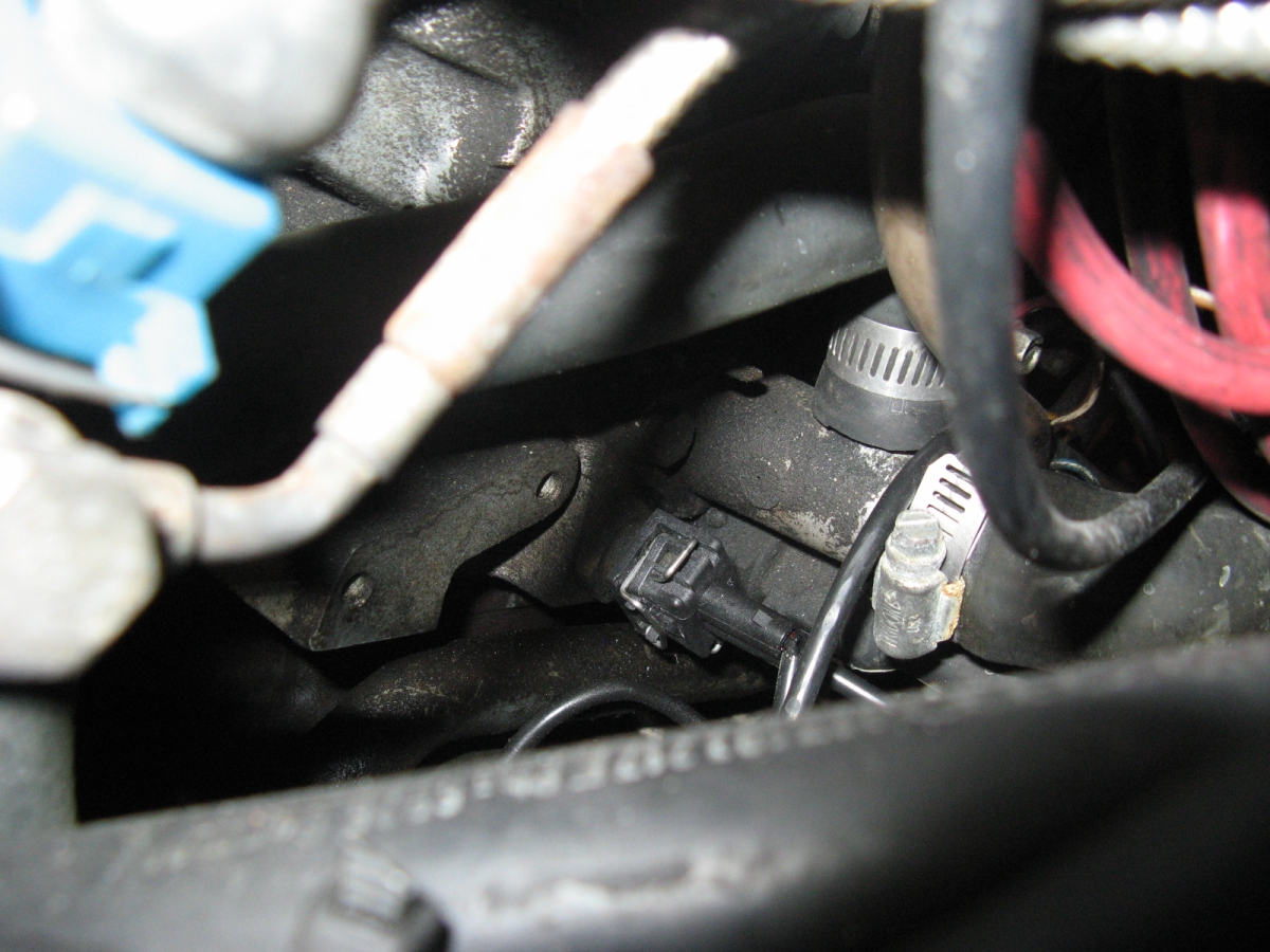
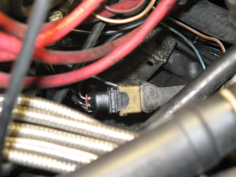
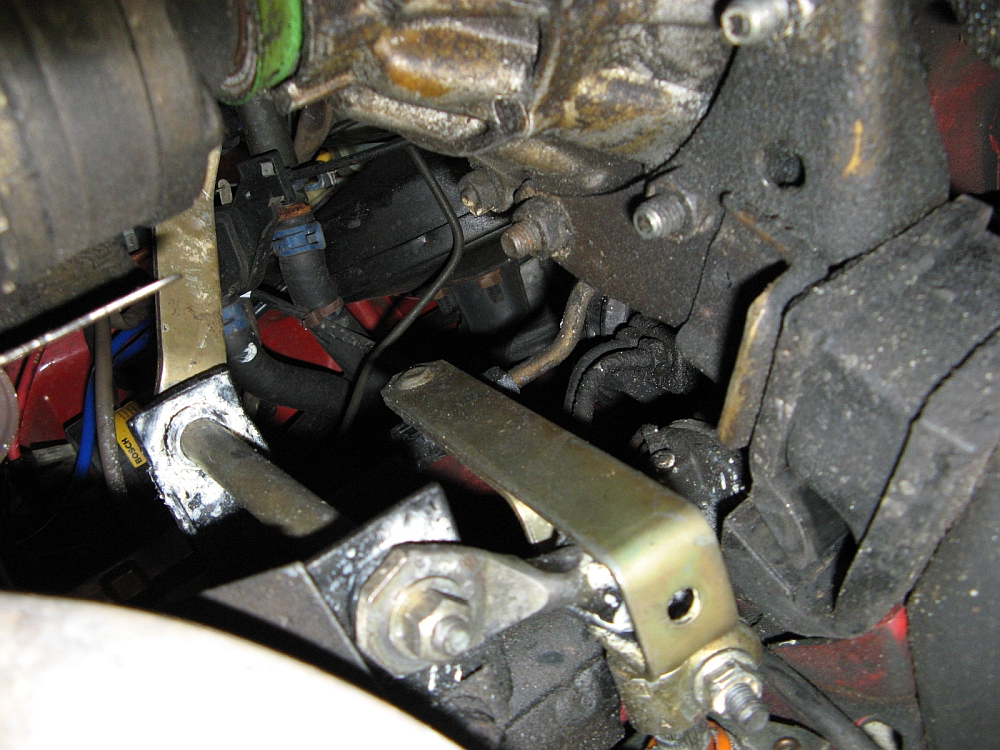
Techtonics Tuning Fuel Enrichment Module installed, installation instructions
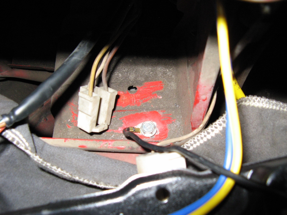
HERE. The white plug for the temperature sensor is located in front of and below the distributor, not to be confused with the hall
sensor plug ON the distributor. Pics L to R: Plug location (pictured with black plug from module already replacing the white temp sensor plug), closer view of
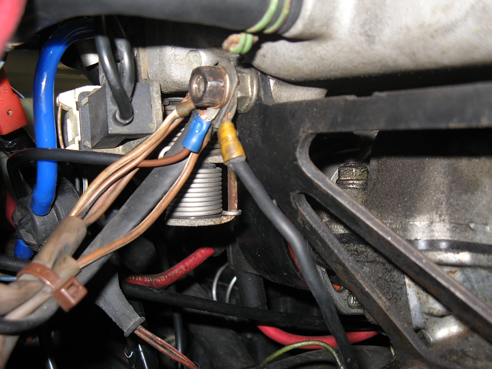
plug location, white temp sensor plugged into module, blue wire/full throttle switch tapped and plugged in, ground wire routed/attached to common grounding point
on firewall side of intake manifold, module zip tied out of the way at firewall:
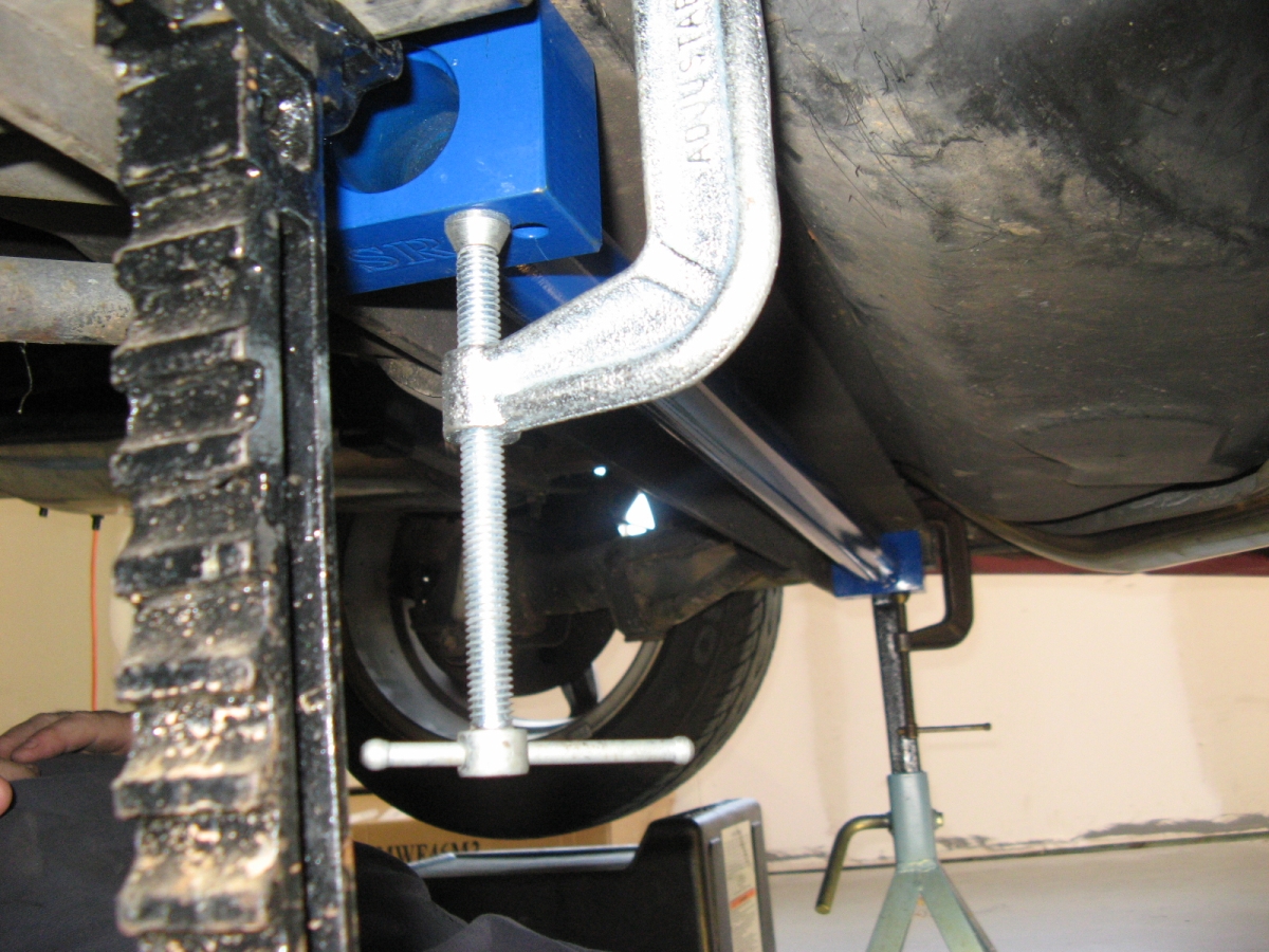
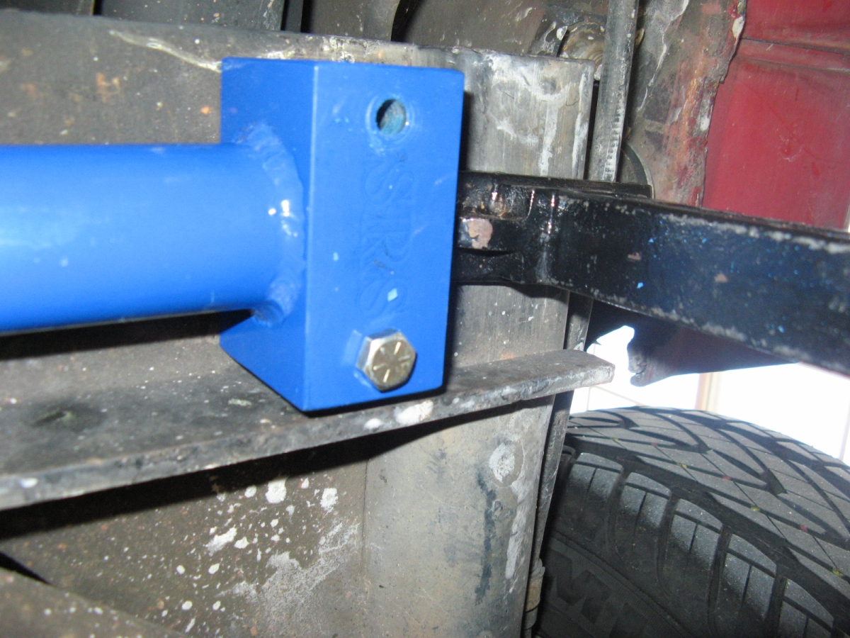
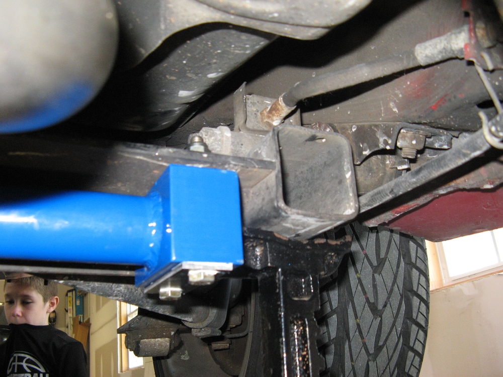
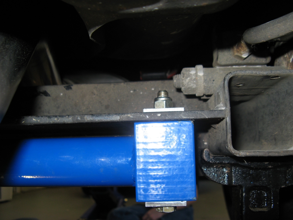
Shine Racing rear sway bar installed. GREAT customer service and support, the guys at Shine Racing were
quick to answer questions and resolve some initial issues.
I started off by backing the car on to Rhino ramps and found that there was not enough clearance for the drill, out came the jackstands. The jackstands were placed
under the rear axle beam pivot mounts. I loosely "hung" the bar on the axle torsion beam with c-clamps so that I could adjust the bar until centered front to back and side
to side. C-clamps were then tightened down and first hole was drilled. Bolt inserted and hand tightened using regular nut (not the NyLock nut supplied), next hole drilled, repeated until all holes were drilled.
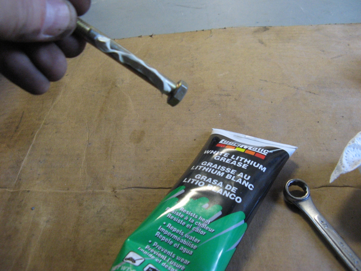
Removed one bolt at a time to clean up the entry/exit holes with a file, bolt was lubed with white lithium grease and then inserted through bottom plate/bar/axle/upper plate
and hand tightened to supplied NyLock nut- repeated until all were completed and then all were tightened using closed end 1/2" wrench on top and a socket wrench on the bottom.
It is a good idea to check bolt torque after a few hundred miles.
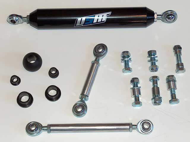
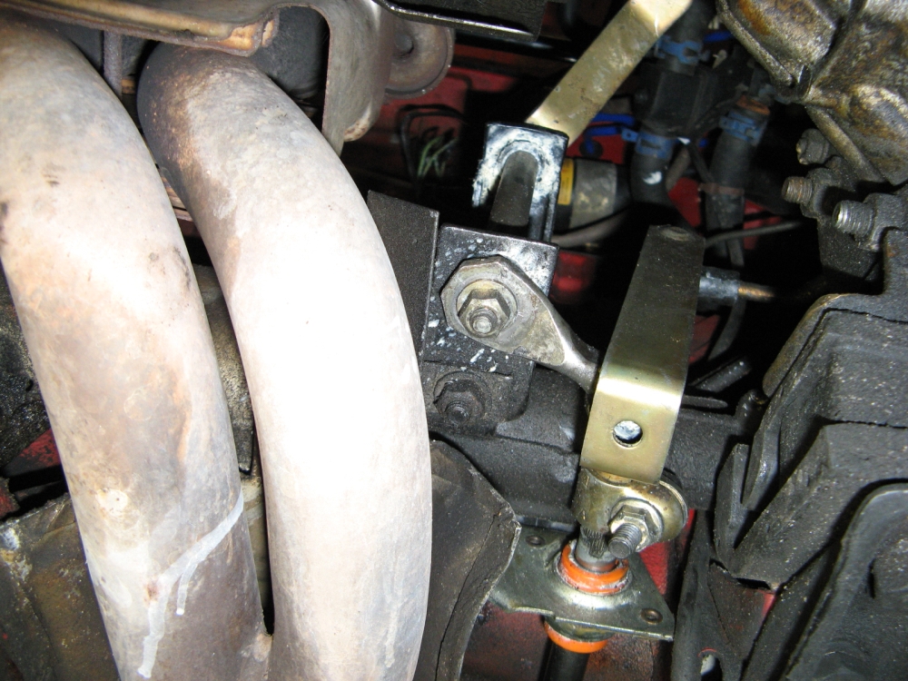
After some email exchanges with BFI (Black Forest Industries) that made it appear customer service/focus was NOT their goal at all, I went straight to the source to order
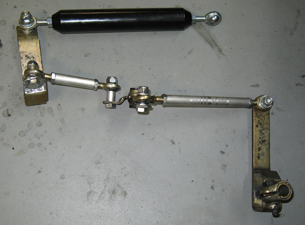
the USRT (Usually Sideways Rally Team)
SmartShift 1 shift linkage kit that incorporates Heim joints and Delrin bushings in place of OE shift linkage connecting points, and includes a weighted
shift rod. Installation instructions HERE.
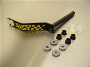
Euro Sport Accessories
short shifter purchased to complement USRT shift linkage. Installation instructions HERE. The short shifter comes with
some spare bushings and some additional Delrin bushings to replace worn OE rubber bushings.
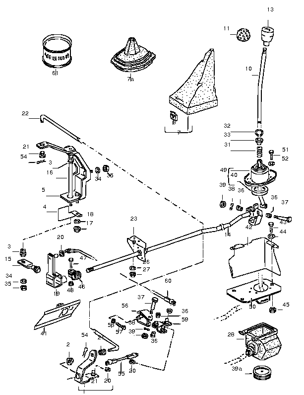
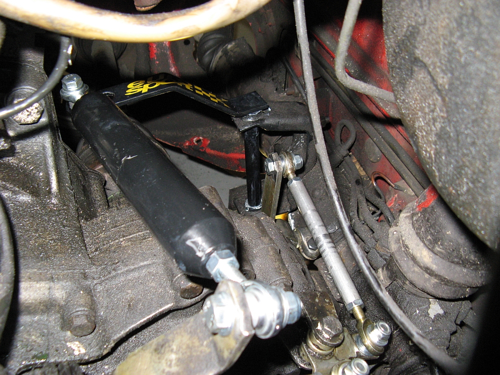
Since this was done while the car was up on jack stands and disassembled for header/exhaust installation, I had decent access to the top for removing the OE
shifter parts and replacing with the USRT kit. In addition, I did have to remove the coolant overflow reservoir to access some of the shifter parts, I just plugged it up
so that no coolant was lost. After removing the OE parts, I adjusted the USRT linkage pieces to the same length as the OE linkage pieces that were removed
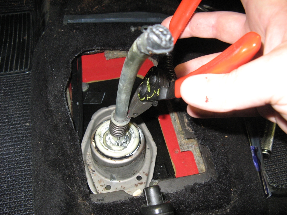
and hand tightened the nuts/bolts. Next, the
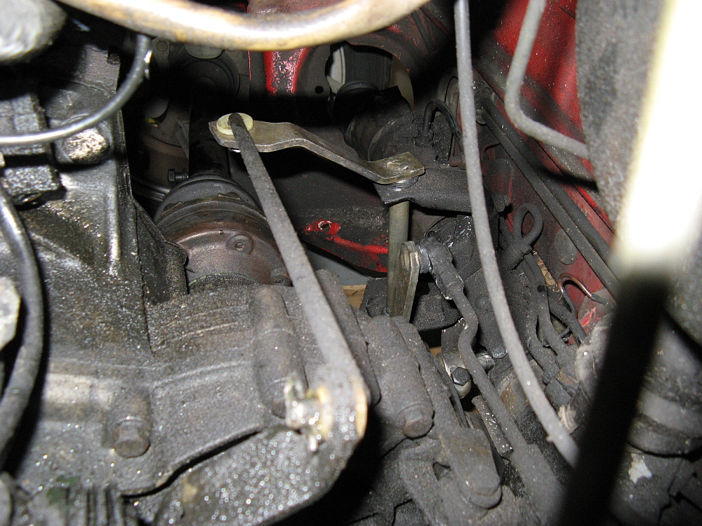
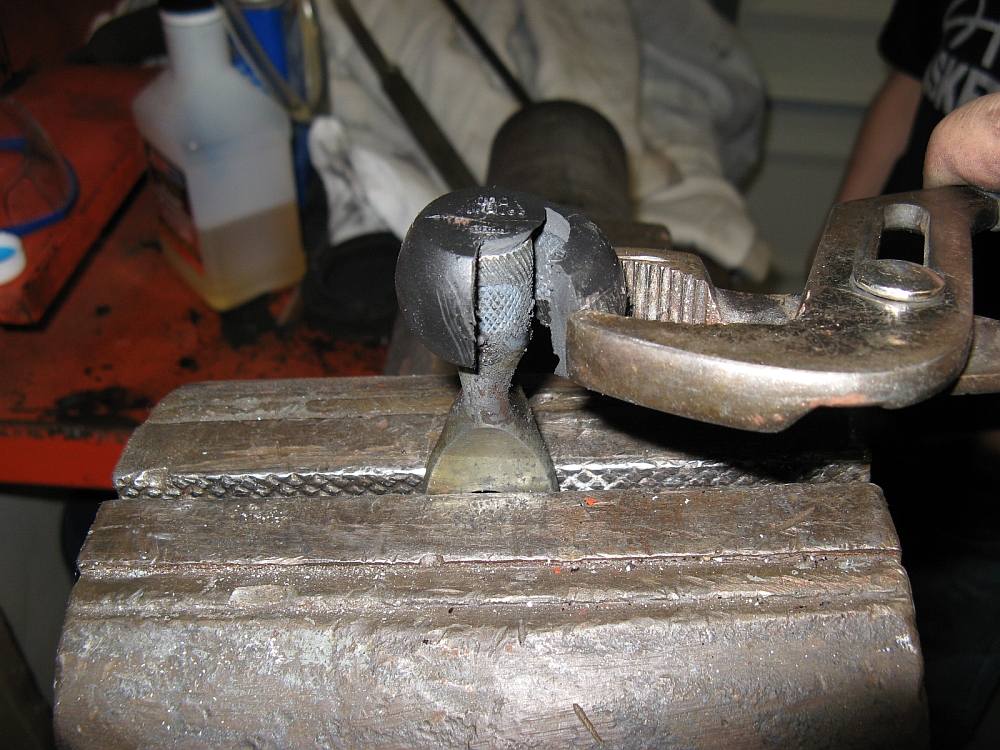
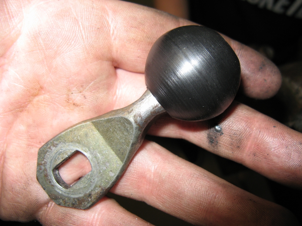
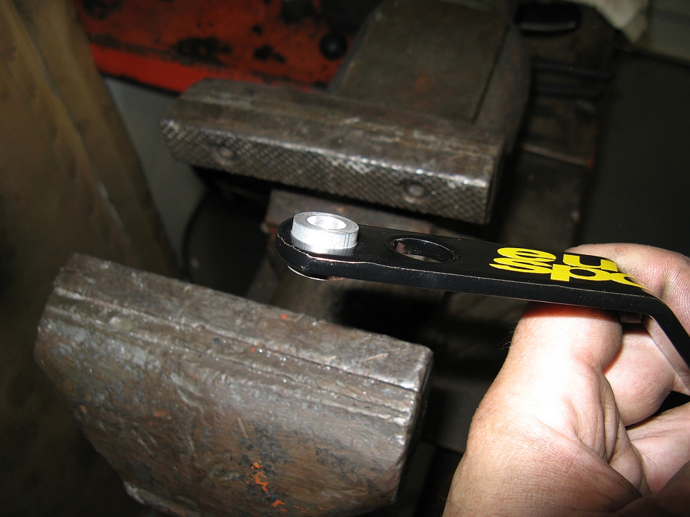
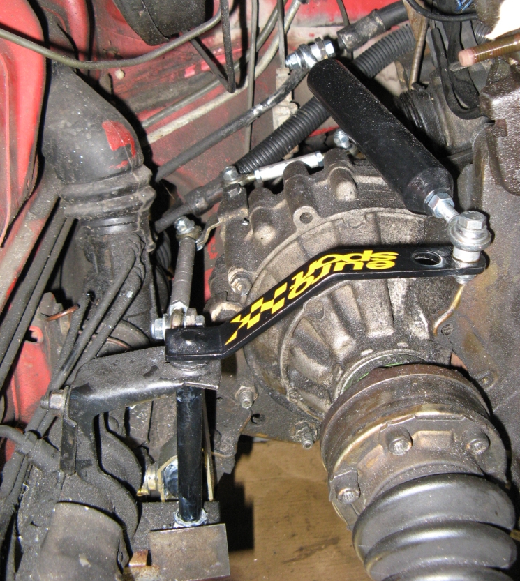
OE pieces being utilized had the ball sockets cut off and holes drilled in their place for the bolts the USRT linkages would use to mount Heim joints. The relay lever
rubber ball was removed and the USRT Delrin ball pressed on to the lever using a vice. [WARNING/NOTE: The USRT piece is designed to work with the OE VW relay lever, the
aftermarket Italian/other relay lever sold by discount parts retailers and installed by some shops have a smaller diameter rod so that the Delrin piece can be pushed on by hand.
I found out the hard way that epoxy does not work in this scenario and have since replaced the relay lever with an OE VW part, at some point I will install the Delrin ball
on the relay lever again, I had to order another USRT Delrin ball after losing the original in transit when the epoxy failed.] I then installed the USRT pieces along with the EuroSport short shifter, the
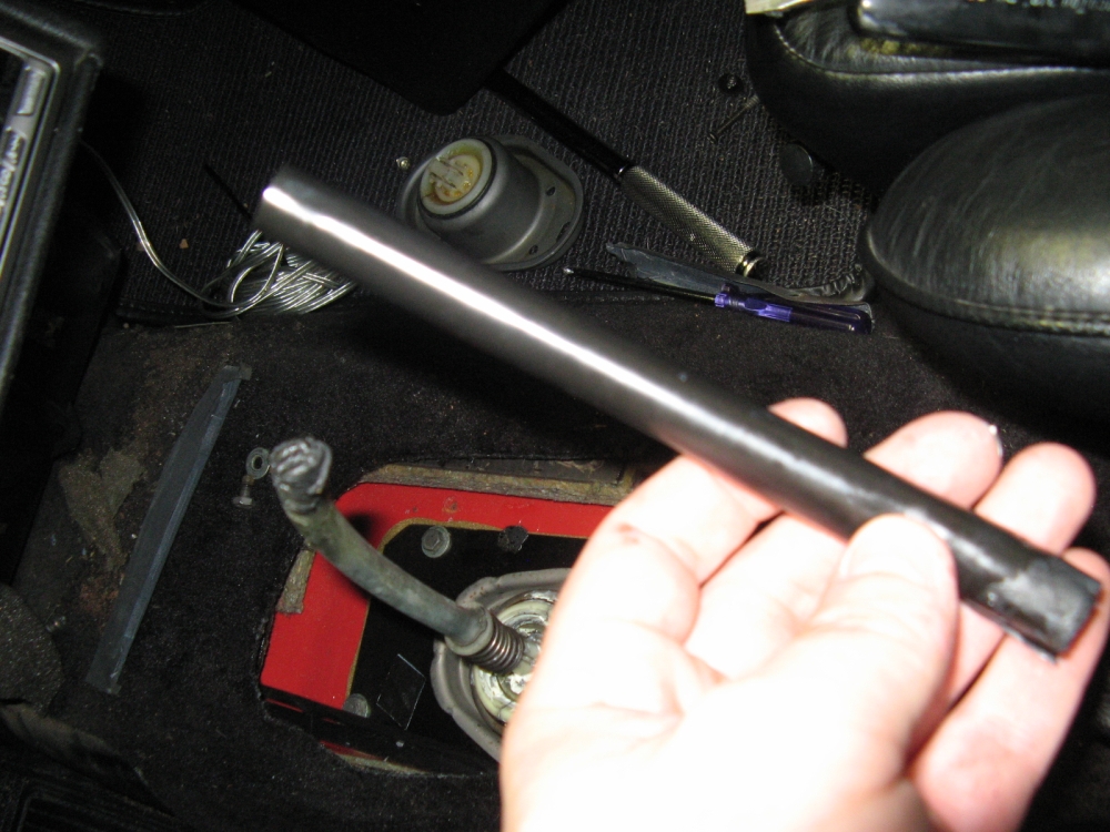
ES SS included new Delrin bushings that were installed in the relay rod holder/bracket and lubed with Lithium grease prior to installing the shifter. The weighted
shift rod included in the USRT kit and associated lock nuts should be installed with blue LokTite to make sure they do not come loose. Once everything was in,
the shifter was so tight it was hard to find neutral,
I attributed this to the short shifter Delrin bushings and after a while the too tight feeling became perfect as the bushings wore in. The USRT shift linkage replacement and EuroSport short shifter feel
SO much better than the way the shifter felt when I bought the car. I probably could have just changed out the bushings to get OE feel but I always use the opportunity to upgrade
when I am replacing failed parts
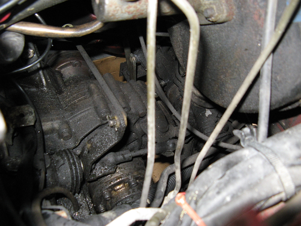
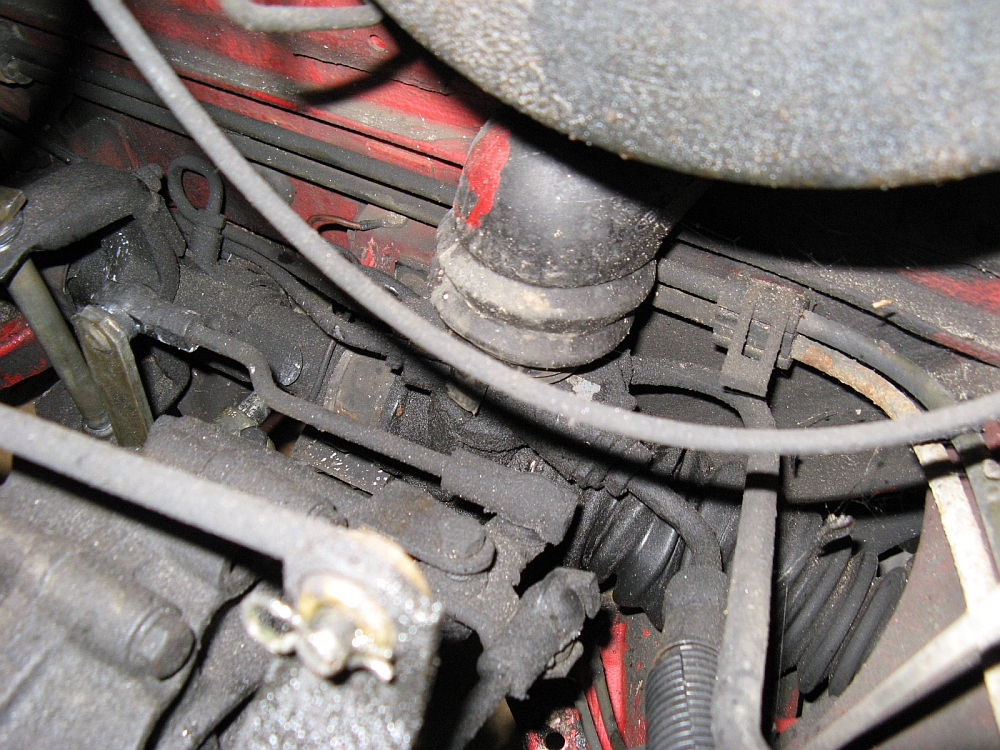
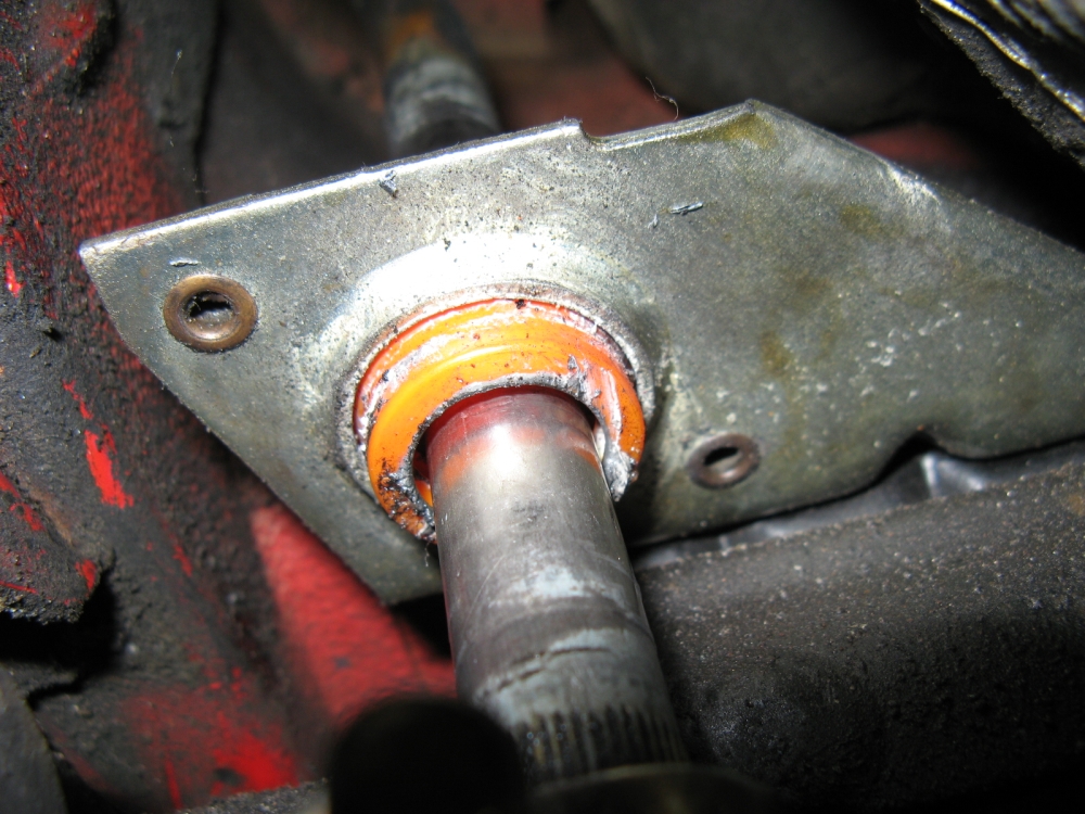
After installing the new shift linkages and short shifter, something still seemed a little loose. Getting under the car and having someone shift while I watched, it
became quickly apparent that the same crack shops that had failed to diagnose the idle issue had also failed when they replaced the shift rod bushing
See the video of the movement HERE.
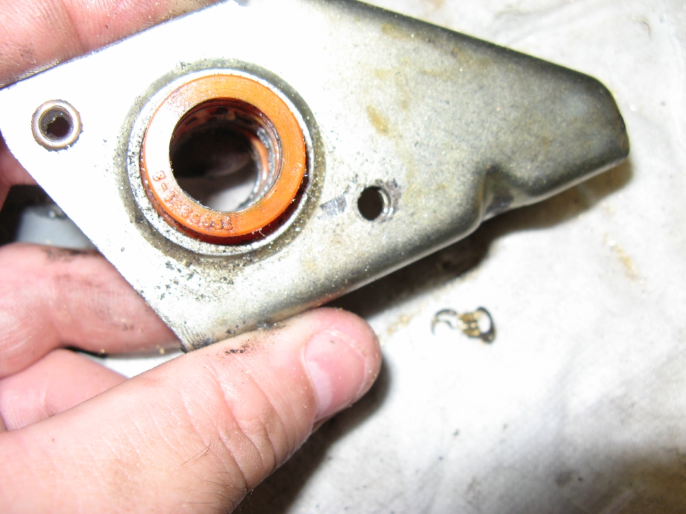
It seems that different VW models used bushings similar in appearance BUT for different diameter shift rods, maybe this was a Golf/Jetta A2/A3 bushing? Regardless, I ordered a new Delrin bushing
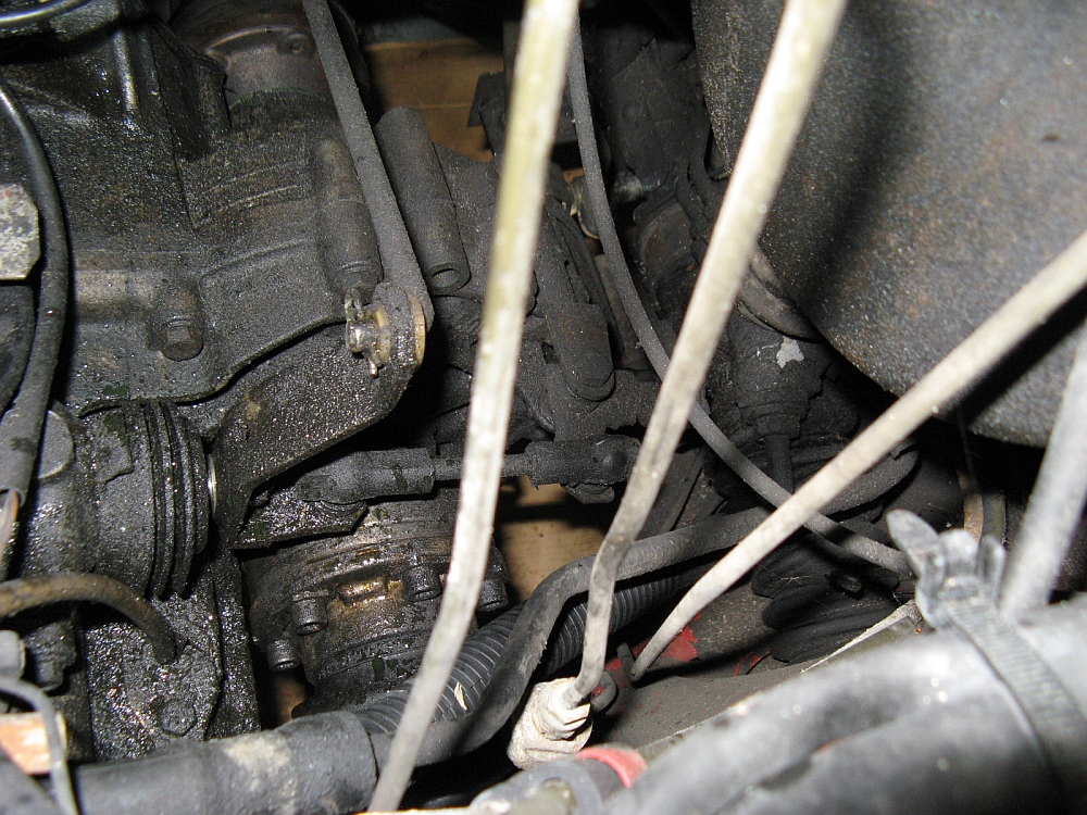
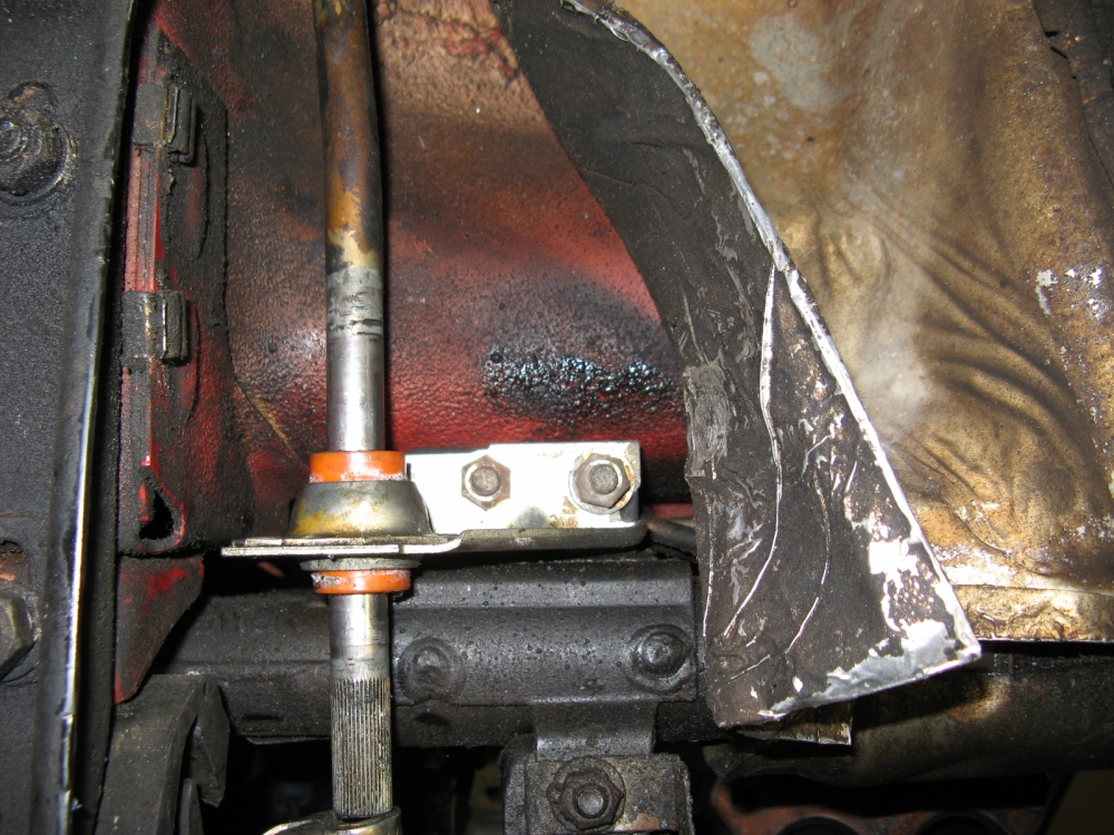
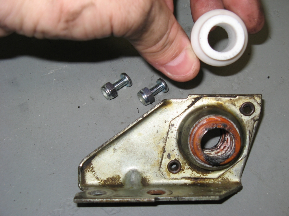
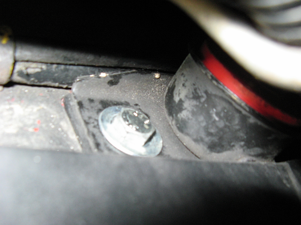
from Missing LinkZ to replace it correctly. This required drilling the rivets out of the
OEM carrier and replacing with bolts/nuts. To remove the carrier from the car, just bend the heat shield out of the way (make sure to bend it back) and remove two bolts.
I also lubed the new bushing with Lithium grease as I had all of the other shift linkage joints and bushings before re-installing it.
This is the way the shifter should have felt if I had bought a car that was maintained by knowledgeable shops:
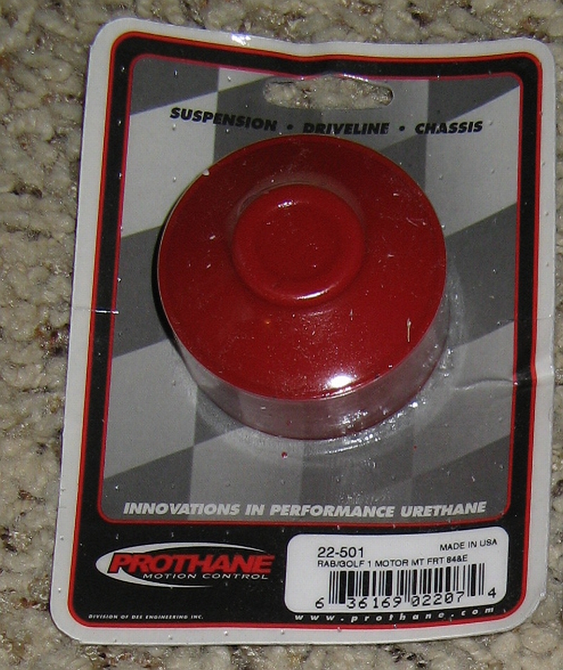
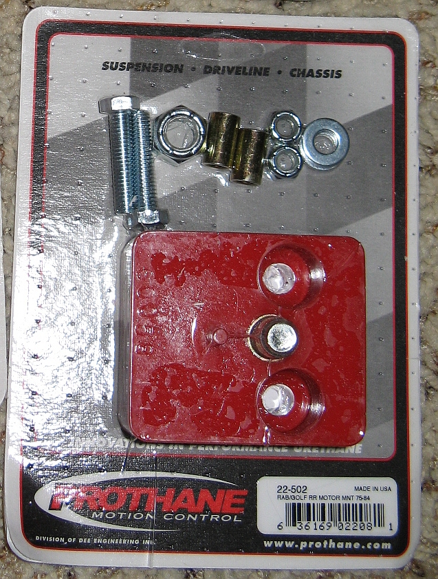
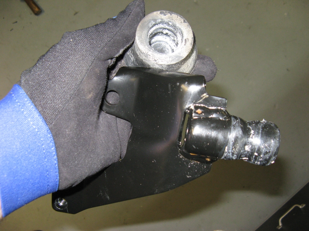
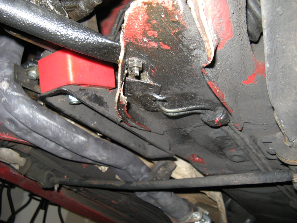
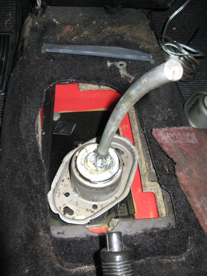
I was underneath the car and discovered the front motor mount had broken. One of the previous owners had installed a poly bushing on this mount and OE rubber on the other three
mounts so the stress most likely caused it to fracture. I bought another OE mount from Dwight Harrison VW
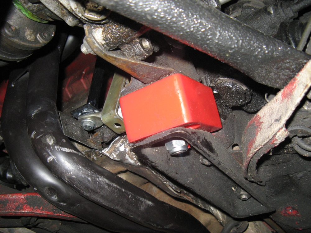
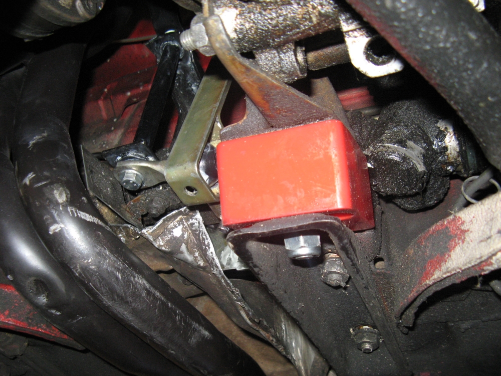
and decided to run Prothane poly again (sourced from
Parts4VWs), but to also change the rear mount out to poly to prevent as much movement up front and promote front
mount longevity
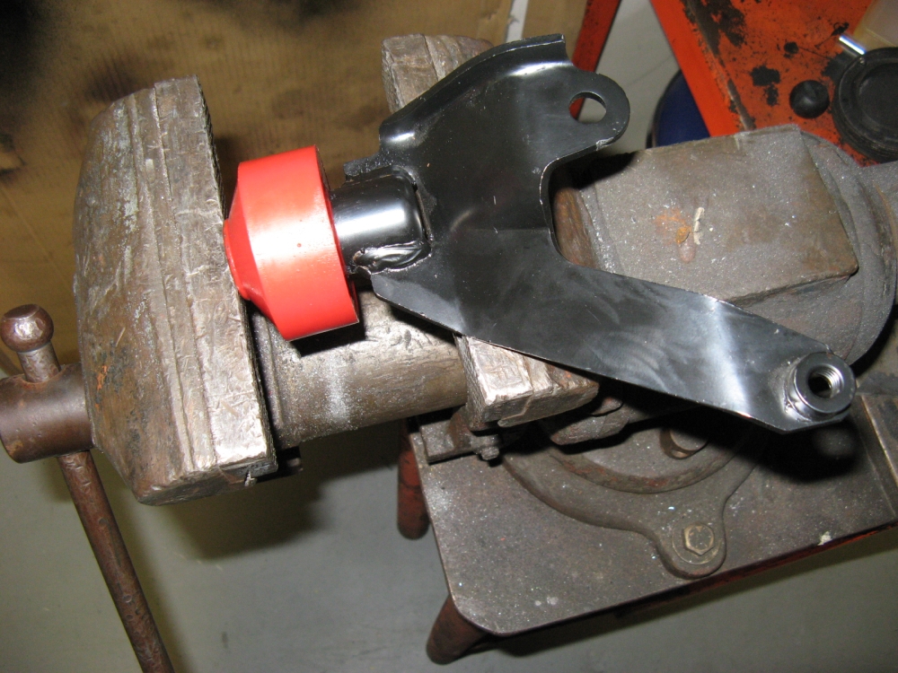
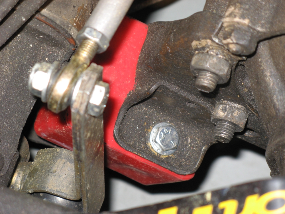
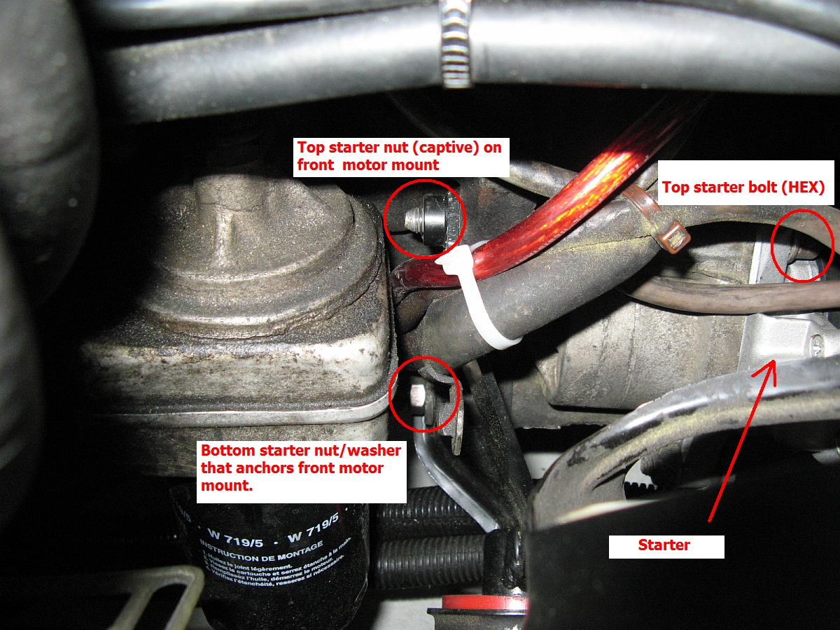
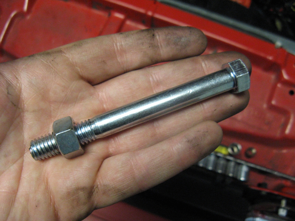
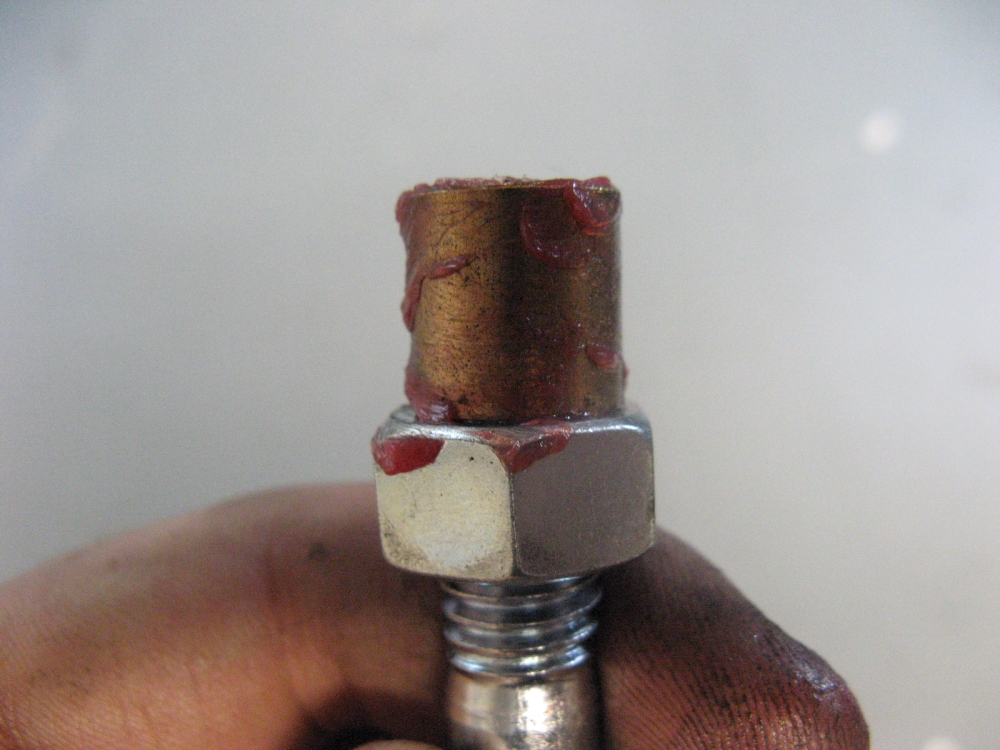
The rubber bushing is removed from the front mount and the poly bushing is pressed into place. The starter bolts hold this mount to the motor, starting the
top starter bolt and then the two mount cup bolts allows for the bottom bolt and nut to be lined up, then everything is tightened down.
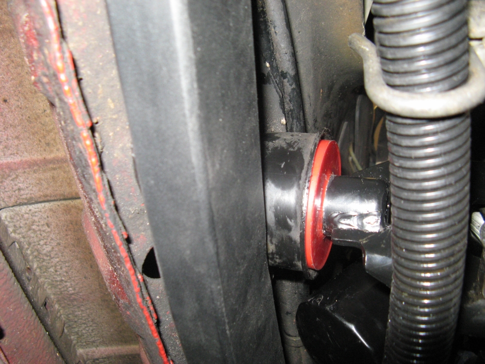
The rear mount is sandwiched between two metal brackets. Using a jack and a block of wood you can support/position the motor/transmission.
Loosening the bottom nut for the mount in the lower bracket and the three bolts/nuts holding the upper bracket to the transmission
is one way to tackle it, or removing two more bolts in the lower bracket allows you to get the entire assembly out. The new hardware that comes with the
poly mount is used in lieu of the OE hardware for attaching the mount to the upper and lower brackets, once assembled it is installed in the car.
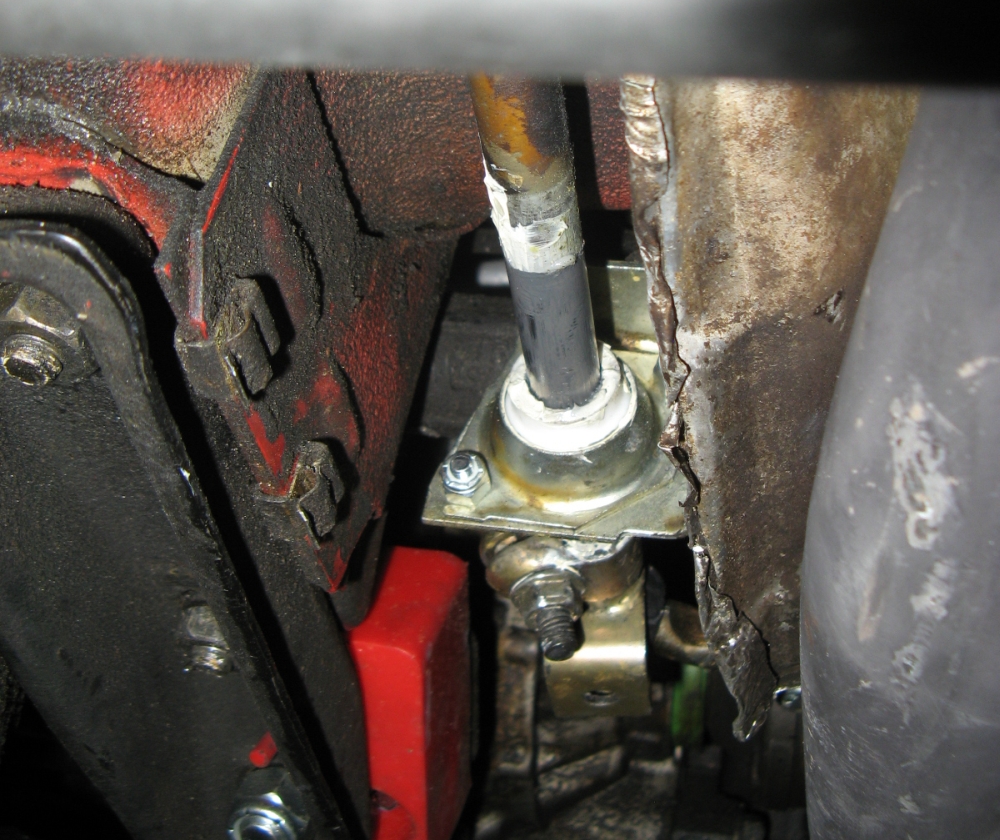
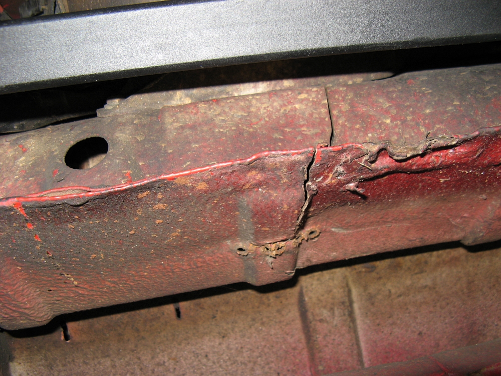
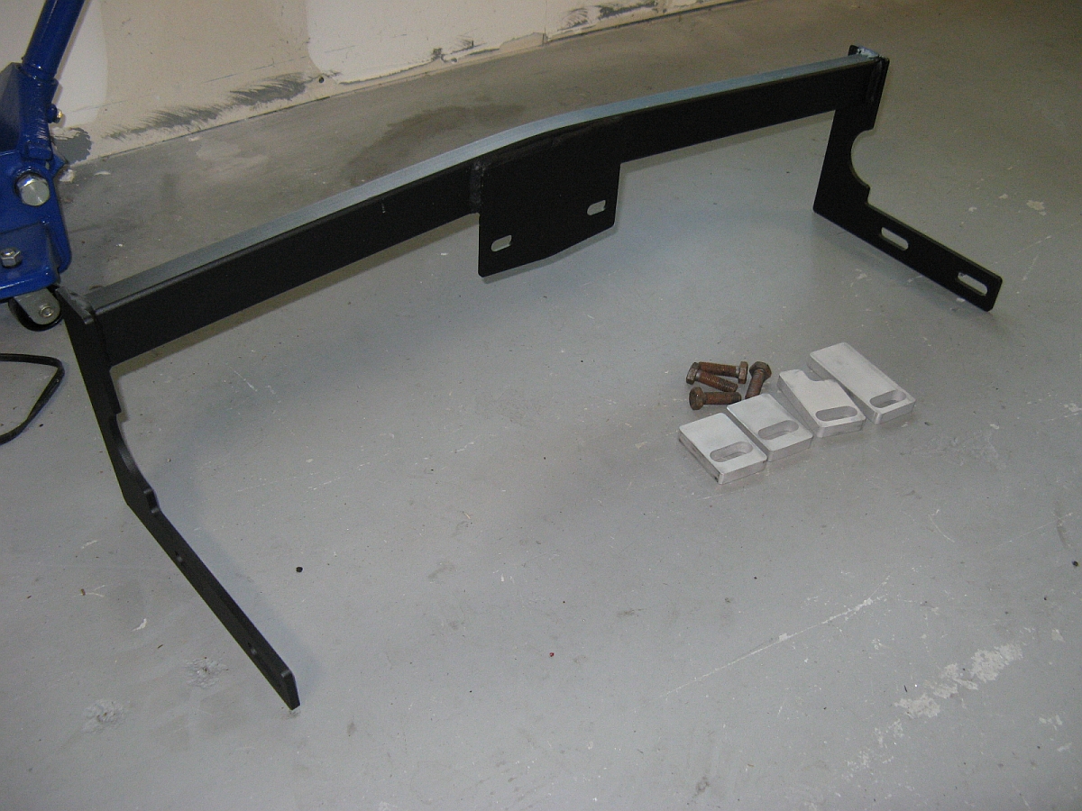
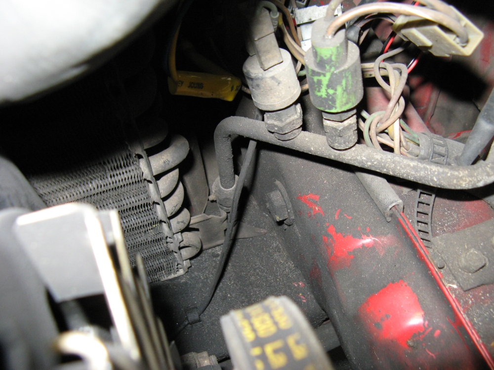
While removing the broken front mount, I found cracks in the front crossmember that serves as the radiator core support AND the front mount support.
Fortunately I had bought one of the crossmember
braces from VW Vortex's GoKraut just in case this ever became a
problem and he was making a limited number (not available anywhere else).
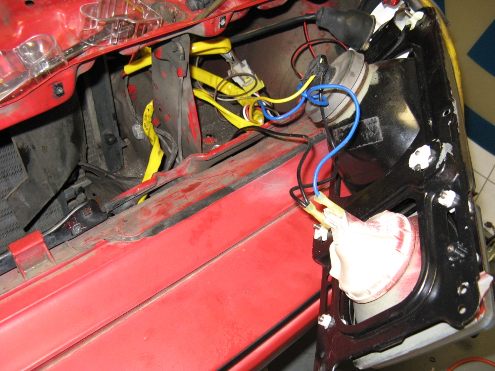
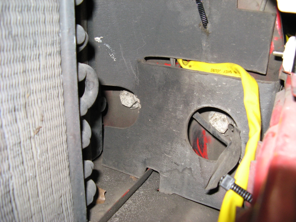
The front grille and headlights were removed so that the bumper mounting bolts could be accessed, two on the driver side can be accessed from the front,
two on the passenger side are accessed from the front and rear. The brace came with longer bolts to accomodate the
thickness of the brace and spacers. I could not get the driver's side of the brace to move forward and could not find what was in the way.....it turned
out to be the plastic protruding from the radiator for the temperature sensor mount was catching the middle edge of the brace. I ended up grinding the brace down by half the thickness around the
sensor area when I had the radiator out, after that everything went into place perfectly. I relocated the horn so it would not interfere.
The supplied spacers are used to keep the brace above the creases in the sheet metal on either side when the bolts are tightened. Remember
to line up the bumper when tightening the bolts that the brace now shares with it. I also purchased new, longer, grade 10.9 bolts for the front motor mount
cup to accomodate the added depth from the brace and to be stronger.
At some point I may try to weld the cracks in the crossmember but the brace should prevent it from cracking all the way through OR in additional places.
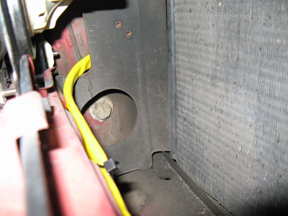
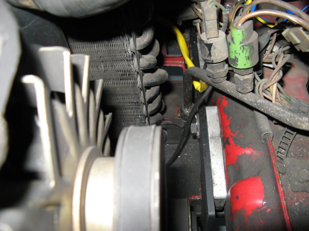
While I had the radiator out (I thought it was leaking when the brace pinched the side, turns out one of the aforementioned Sarasota shops had not tightened the
temp sensor), I decided to replace it with a newer part. I first tried to order a radiator at the local McParts store, they had one part listing for my car with A/C.
When it came in I went to pick it up and noticed the neck was not angled but went straight back, it would have hit my alternator (maybe this was the non-PS
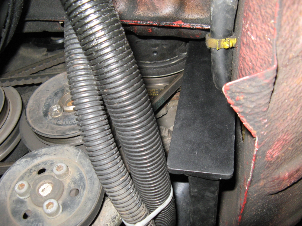
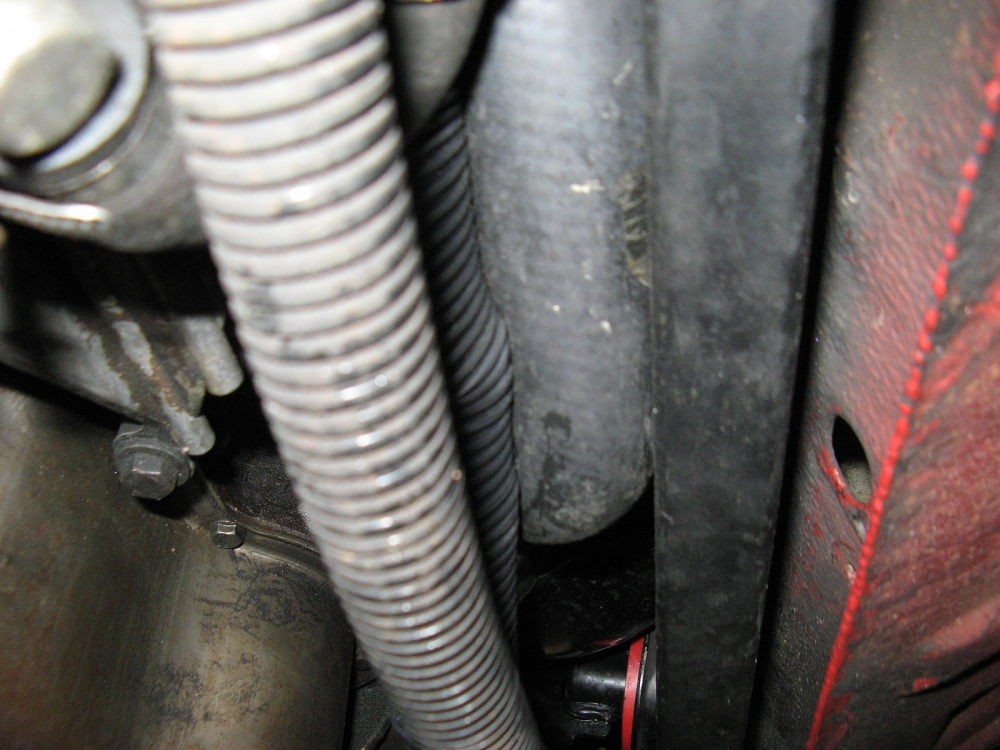
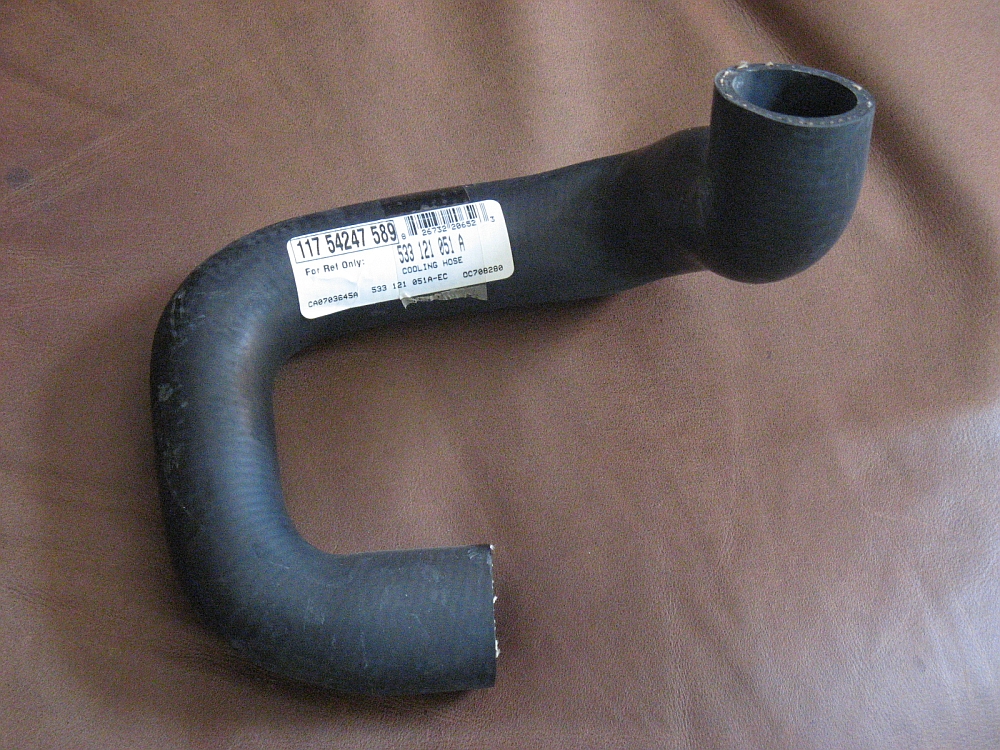
version?) I ordered a Nissens radiator from MJM Autohaus. I also found that the lower radiator hose
had a wear spot so decided to go ahead and replace that while everything was apart, I found this at Techtonics
Tuning, this is another part the local McParts store could not get right. I re-used the rubber grommets that go around the two lower mounting pins to
cushion the radiator, it might have been a good idea to try and source those as well:
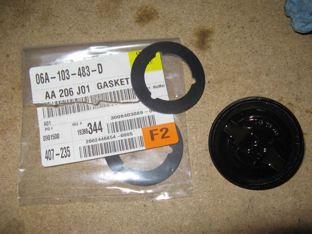
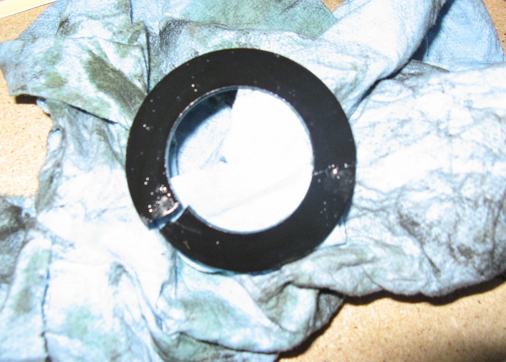
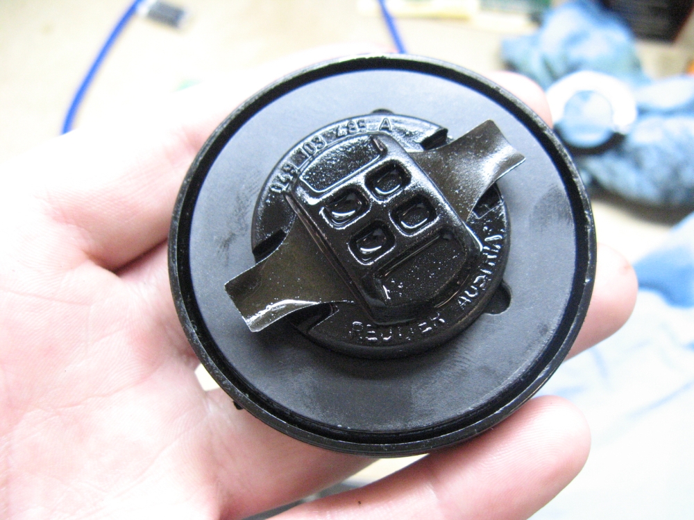
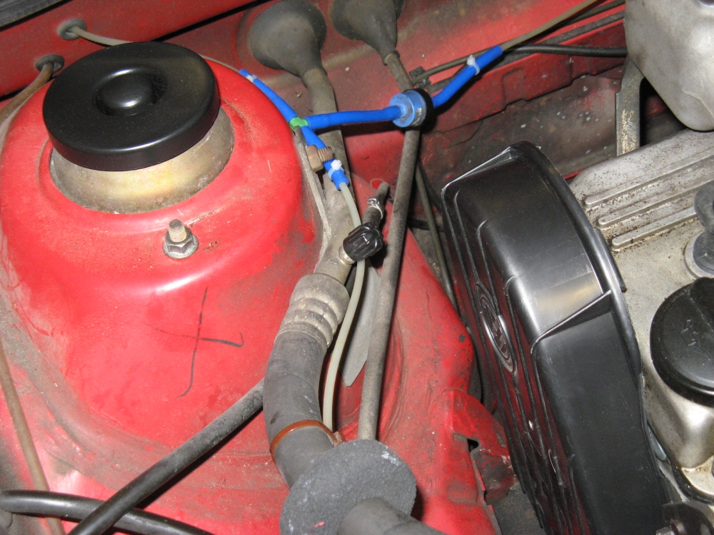
Do you notice oil accumulation on your valve cover? It could be as simple as replacing the oil cap seal. Mine was so old (maybe original?) it was like plastic
instead of rubber....
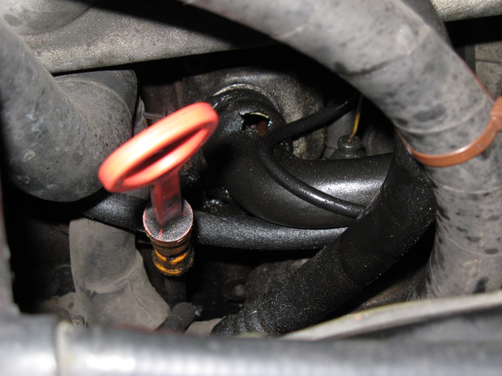
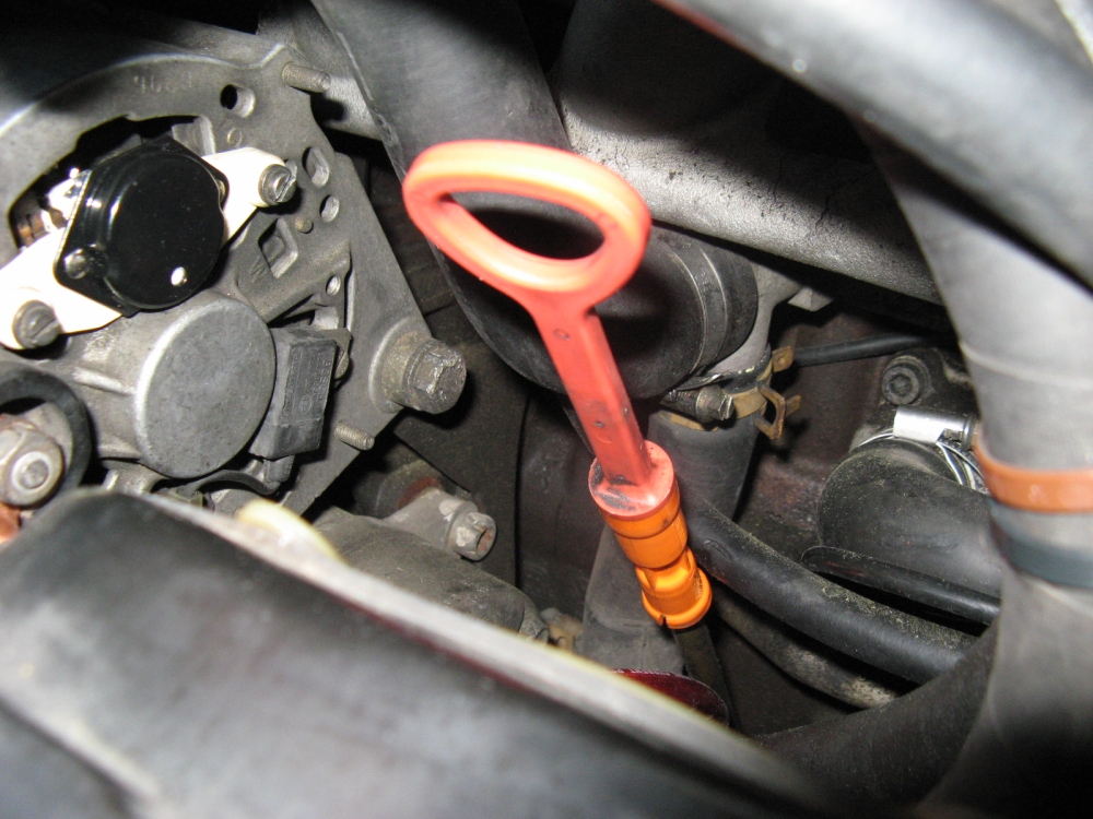
After installing the new oil cap seal, I go to check the oil level and when I pull the dipstick the plastic receiver/receptacle (aka funnel) comes up with it.....
I am guessing this is another age/heat related failure so I went ahead and ordered two. Picking the pieces of the old funnel out of/off of the dipstick tube
was a lot of fun so I am thinking it is better to check and proactively replace before it disintegrates. The new one just pushes firmly down over the dipstick tube,
just make sure it is on all the way (it is a TIGHT pressure fit) so the dipstick readings are accurate:
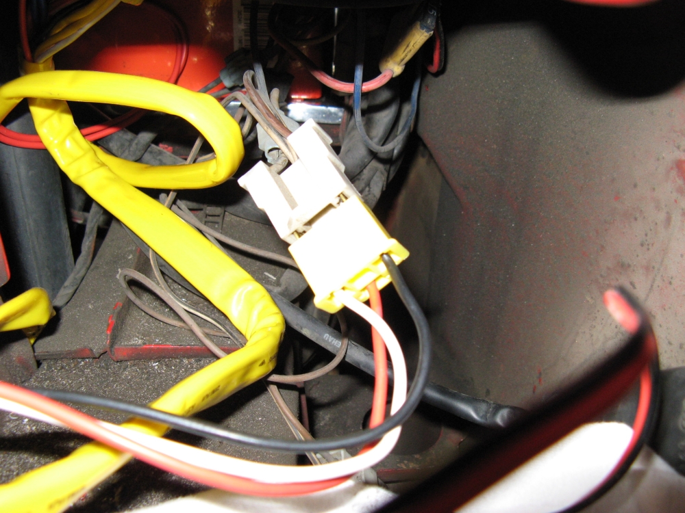
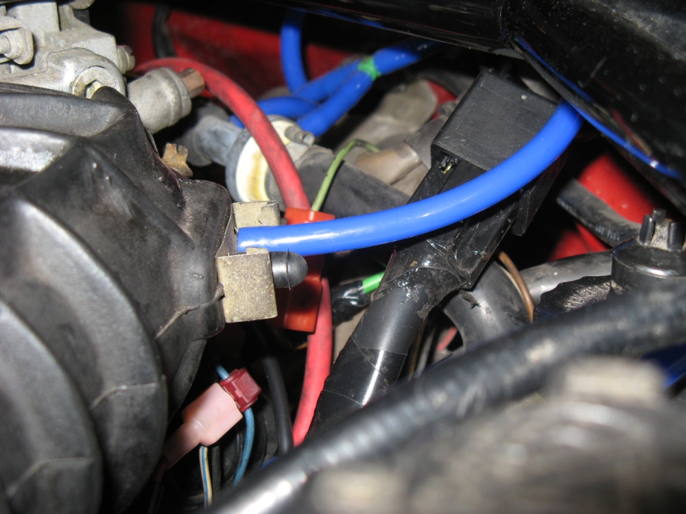
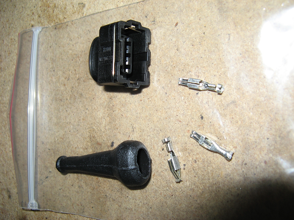
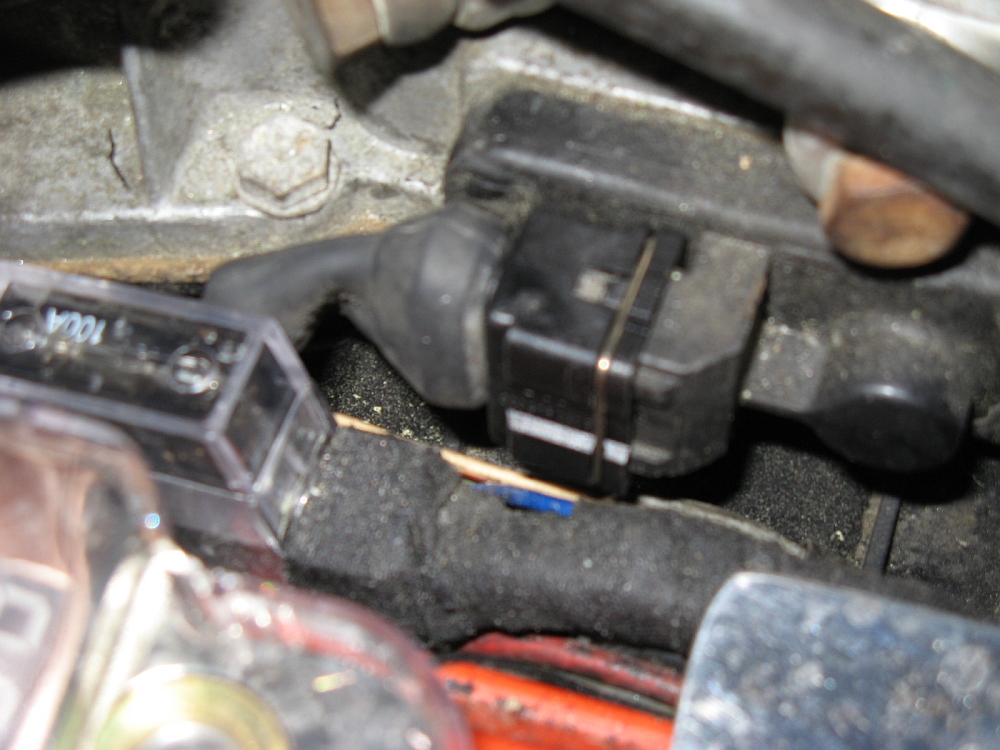
I found a plug that was hanging on by a prayer, looks like one of the shops that was throwing parts at the idle problem (including a fuel distributor) put silicone in the plug to hold it
together. I sourced a new 3 pin AMP connector from Eagle Day Parts to replace the old
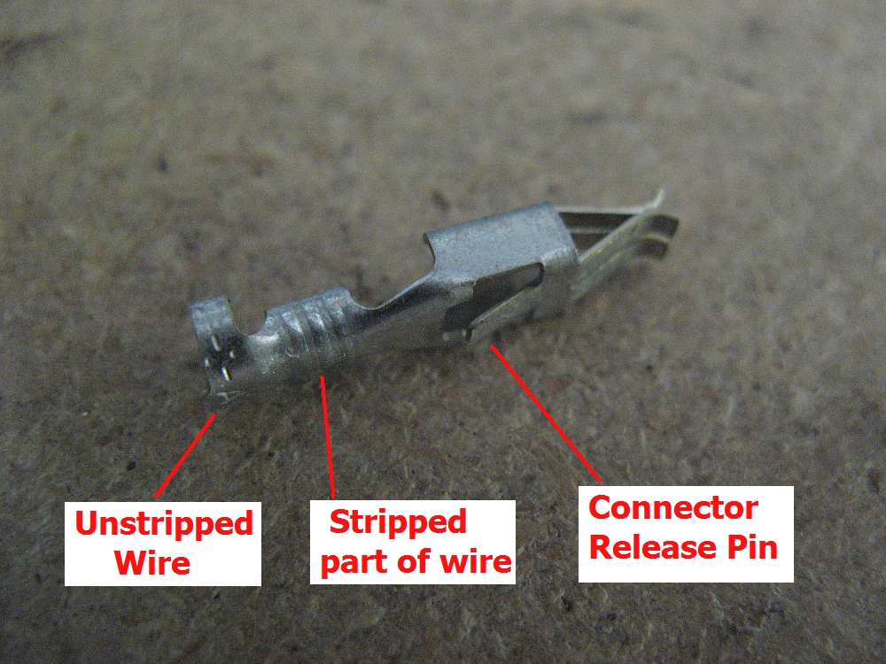
connector. It came with a boot and new pins, I decided to keep the old boot since it was in good shape and sealed each wire independently, but did crimp and solder on the new pins
for a clean new connection. There are two crimp sections per pin: one for the unstripped part of the wire and the larger one for crimping the stripped section.
Of course you can always pull the old pins from the old plug using a pick or removal tool and re-use them. Also, write down the wire colors and plug location or take a picture before
changing out plugs
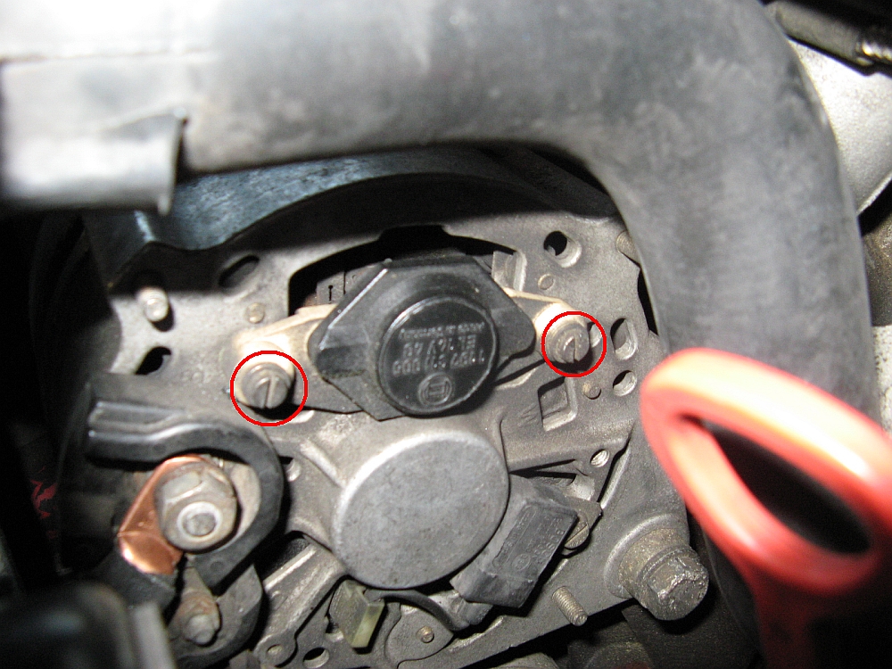
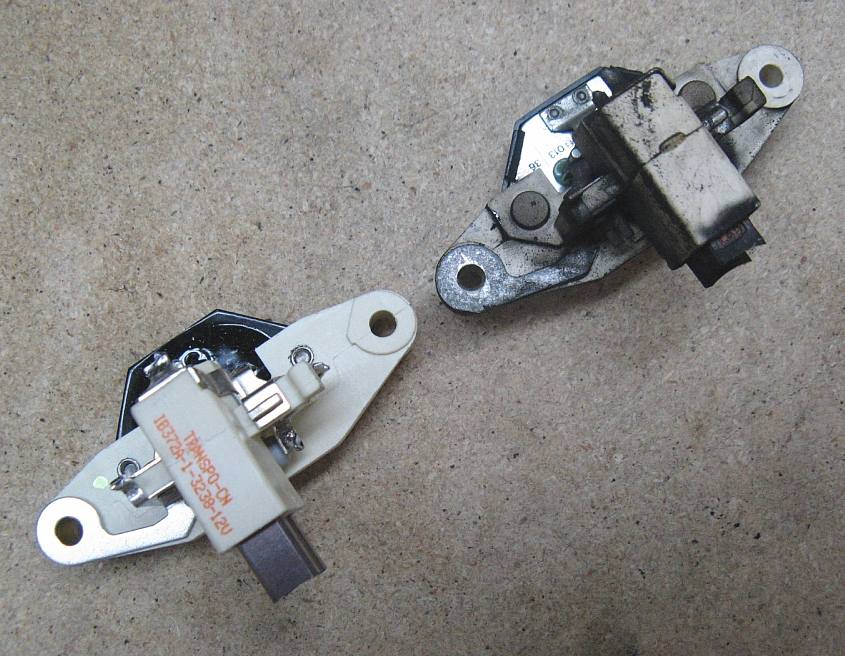
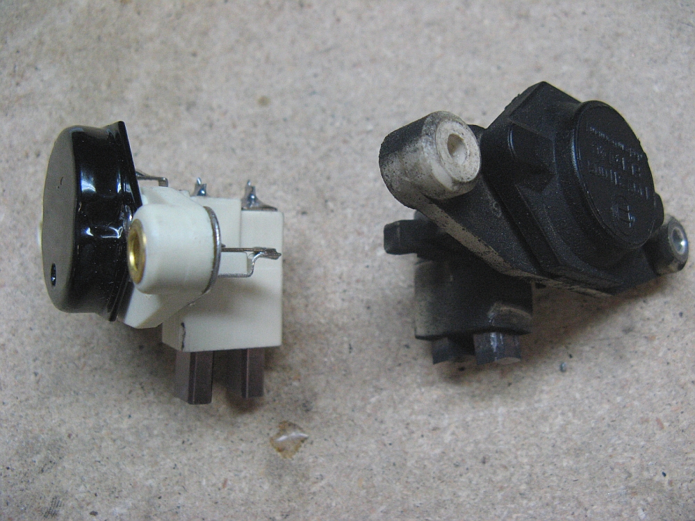
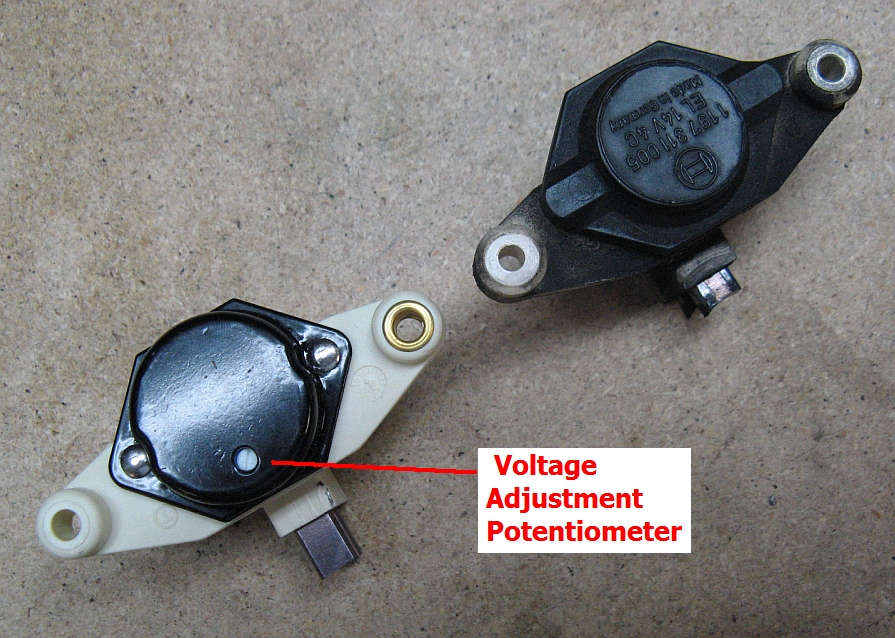
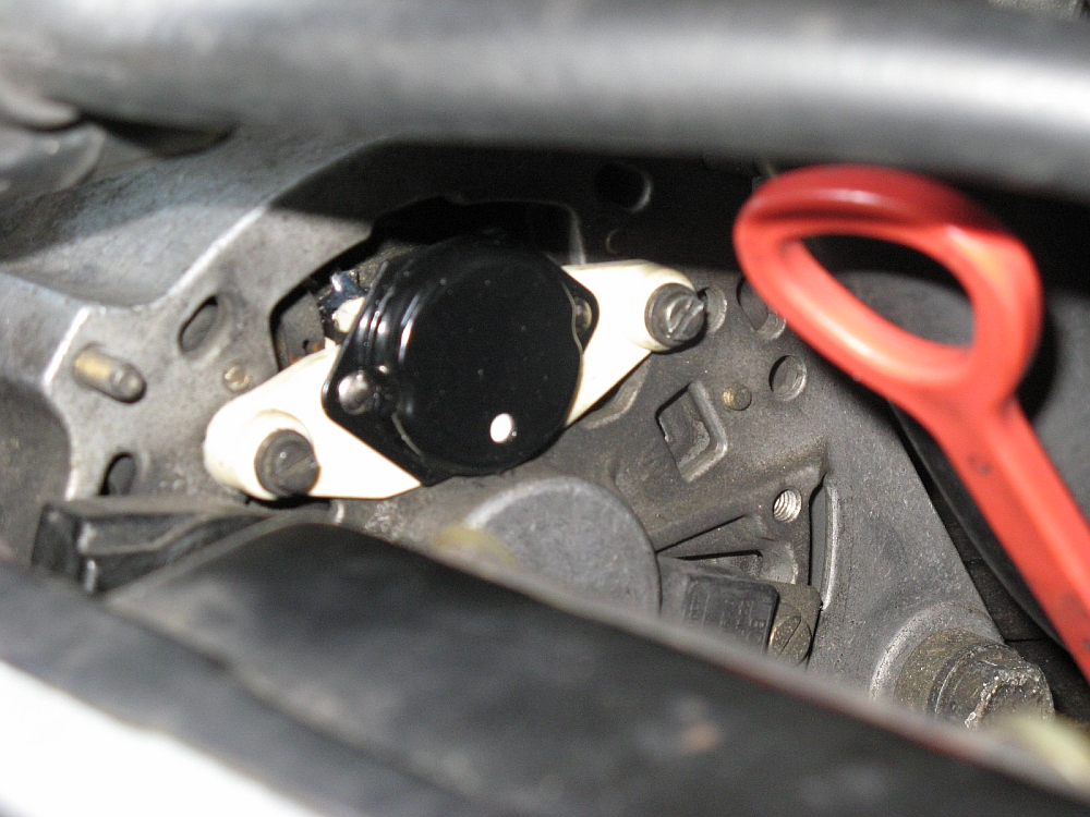
I noticed that the alternator voltage had seemed to drop a bit since the car has been driven in the past few weeks and decided to go ahead and order an
adjustable voltage regulator from Dave Barton.com, I ordered the internally adjustable model
since it would be easy to access for adjustments. I disconnected the negative battery terminal, removed the two screws holding the regulator in the alternator,
and installed the new one. I reinstalled the battery negative cable and cranked the car up, when hot and while running I set it up a few tenths of a volt
to 14.5v. As it turns out, the brushes on the 18 year old alternator voltage regulator (it had been replaced by the PO in 1992) were close to worn out (spec is 5mm)
and probably about to give up at some point not too far in the future.....glad I didn't wait for the alternator light to come on:
The doors did not seem to close as good as they could and I found the insulator entirely missing on the drivers side door striker pin. I ordered two and installed them
in about 5 minutes, I used a 15mm wrench to remove the old ones and the new ones were installed with a 14mm wrench. The nuts are captive so no need to worry about
dropping them down in the black hole behind the rear side panel. Doors close solid now and line up better with the car body:
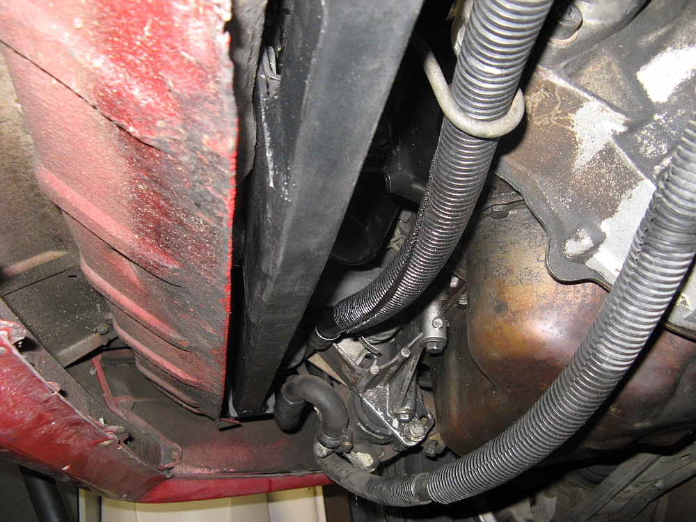
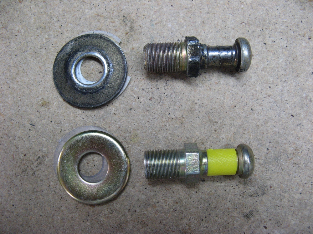
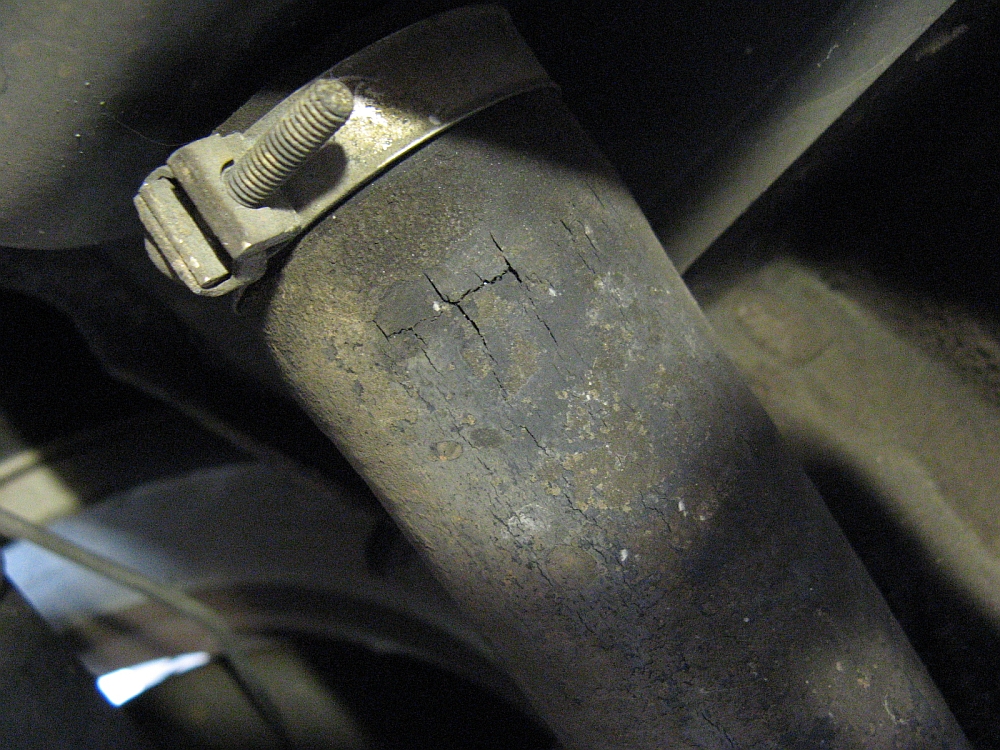
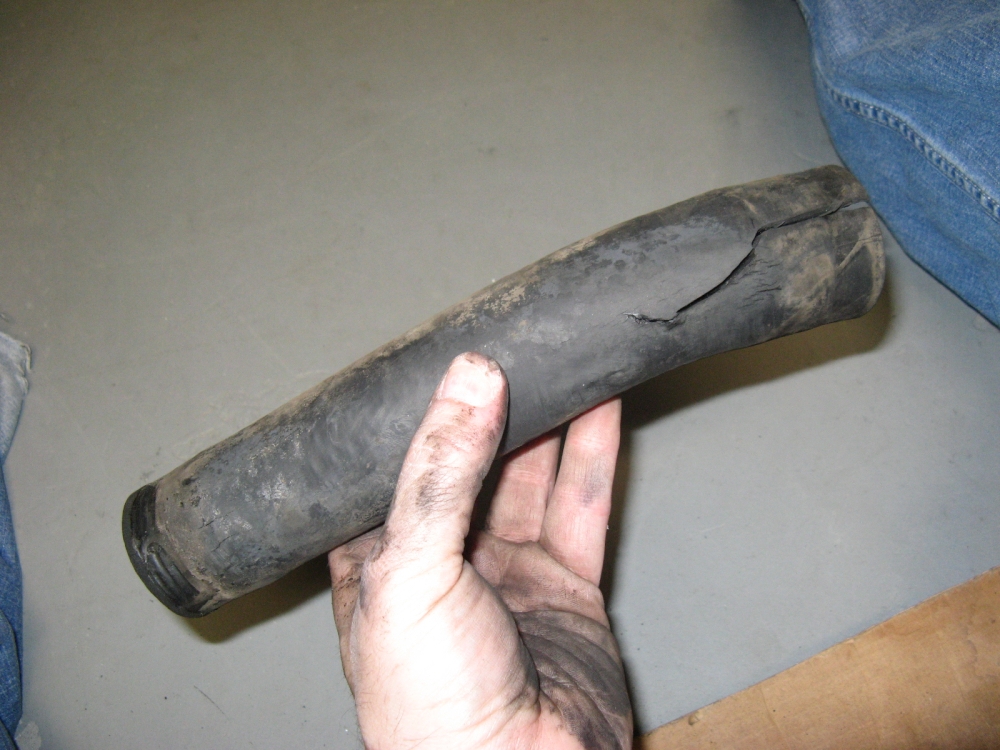
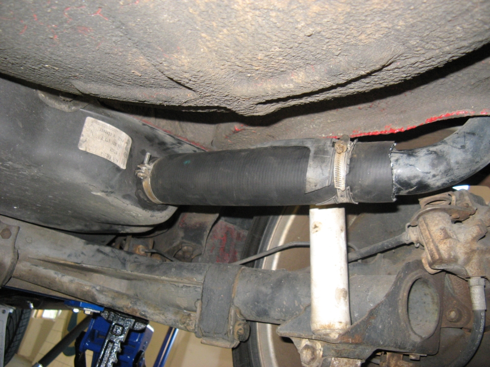
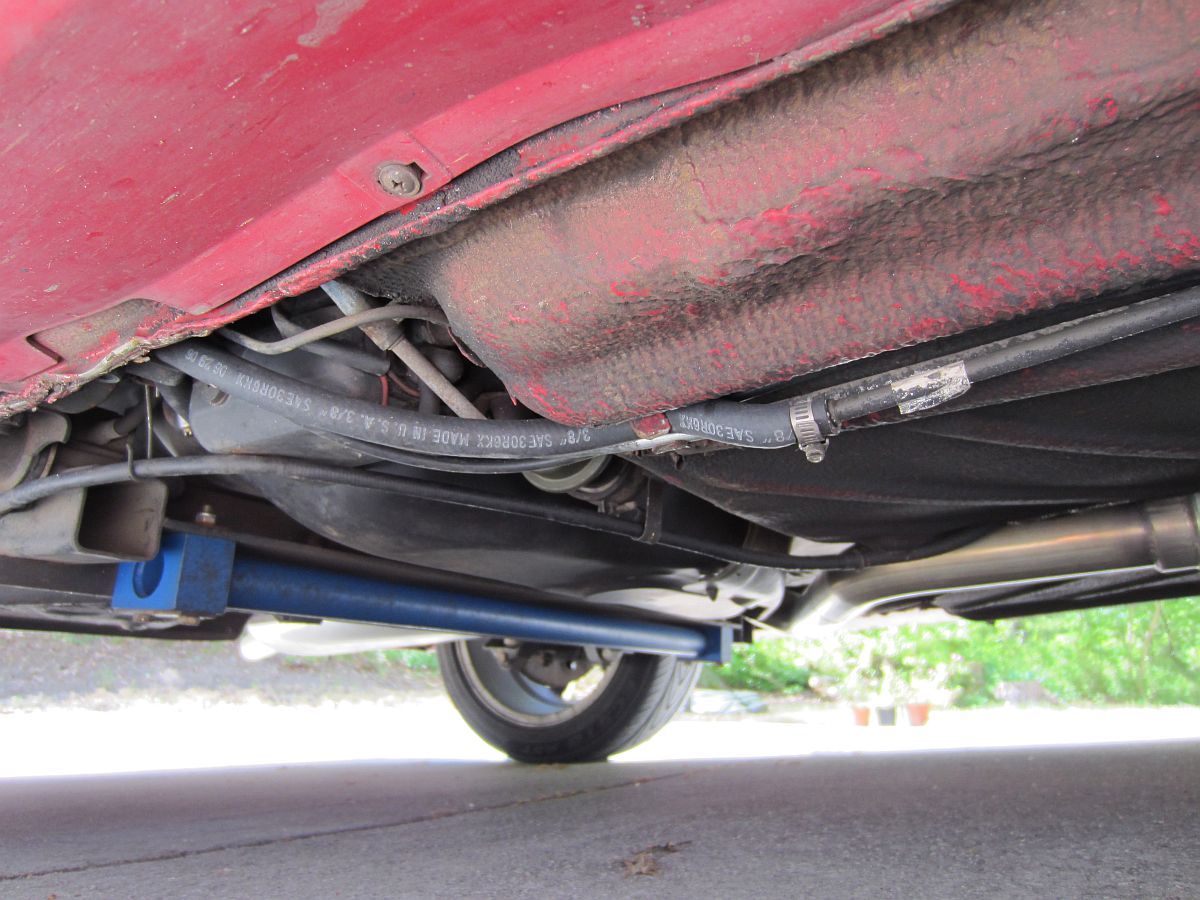
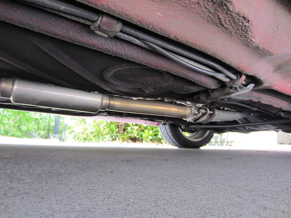
While installing the Shine rear sway bar, I happened to look over and see the gas filler pipe to gas tank hose and it looked sad. I was not able to get in touch with
Mike at Forge in time to get
some 41mm ID fluorosilicone hose that would outlast the car (P/N SH-41/FL). I was able to find some 1 3/4" fuel hose at NAPA, who swore they could not get
41mm. I bought a foot since I needed 9", it was $16. So far, it has not leaked and appears to be working fine, it appears that the clamps were able to
clamp down hard enough to soak up the extra 3mm of diameter. Forge kit is on the way (Thanks Mike!)
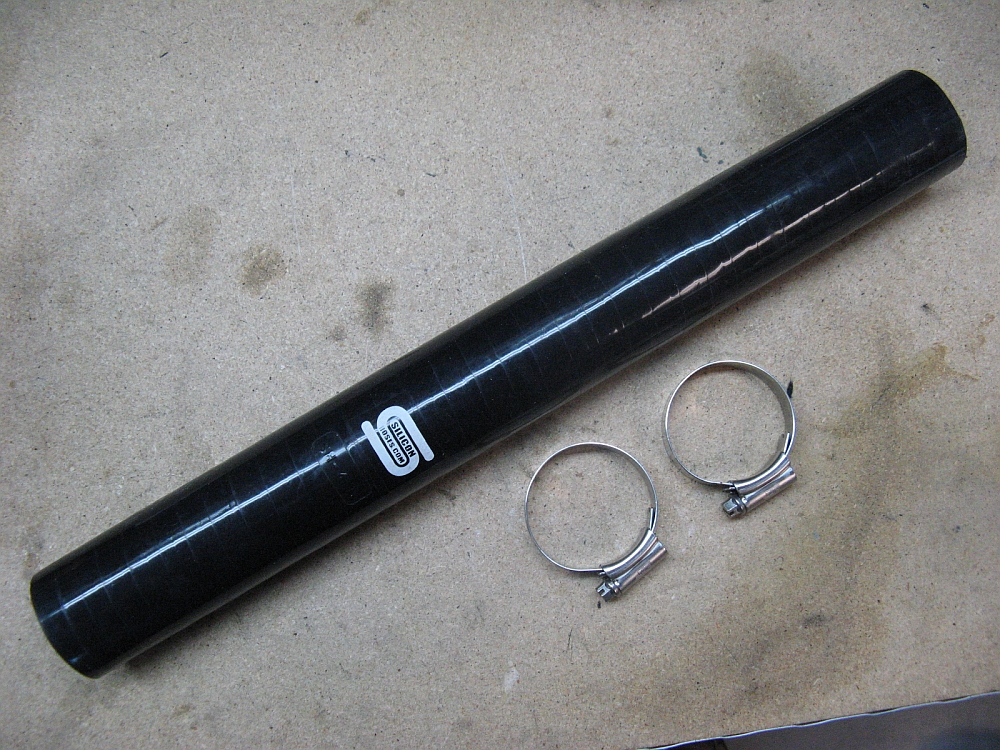
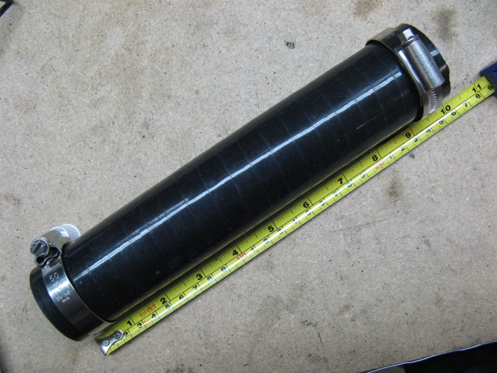
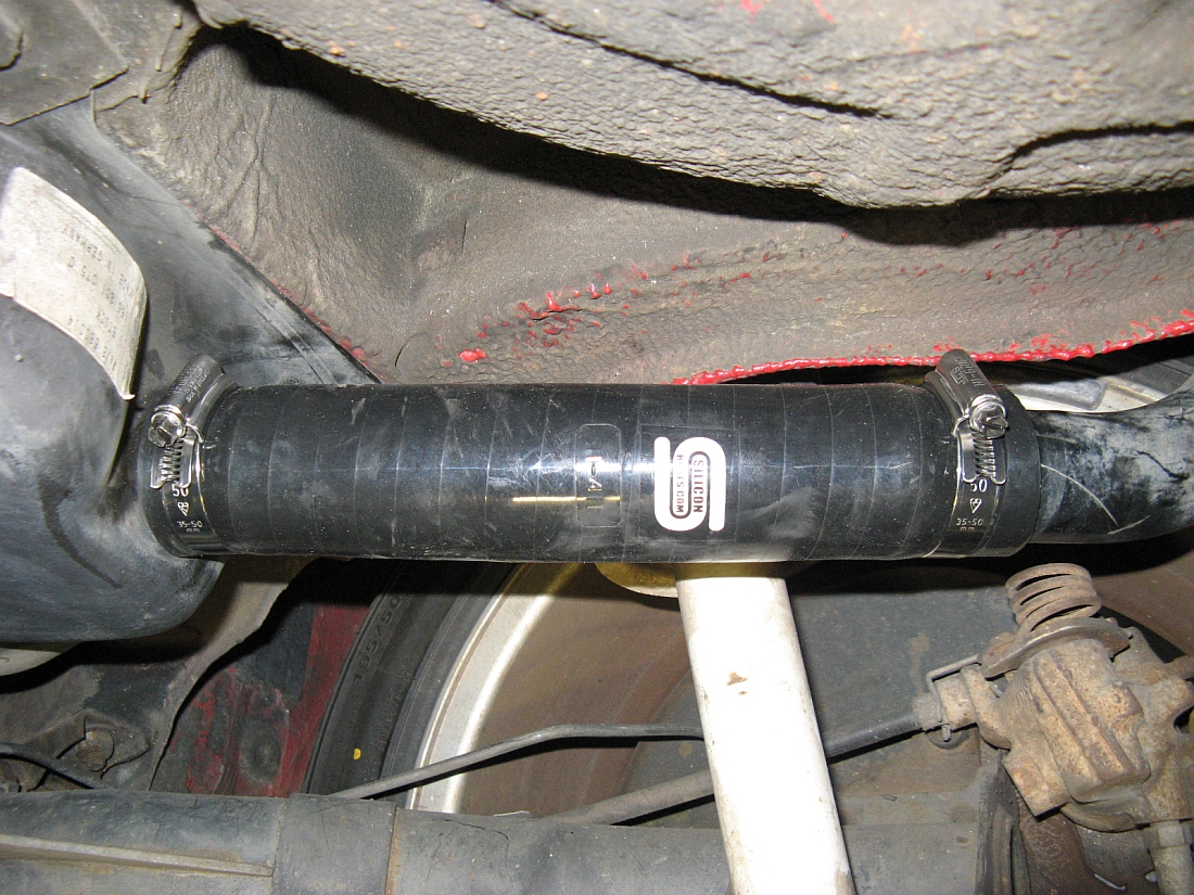
UPDATE: Forge kit arrived and has been installed. I measured the required length of hose as 9.75" and cut the hose (I ordered the 16" kit), then installed
it with the supplied stainless steel clamps, smooth on the inside so the hose is not damaged.
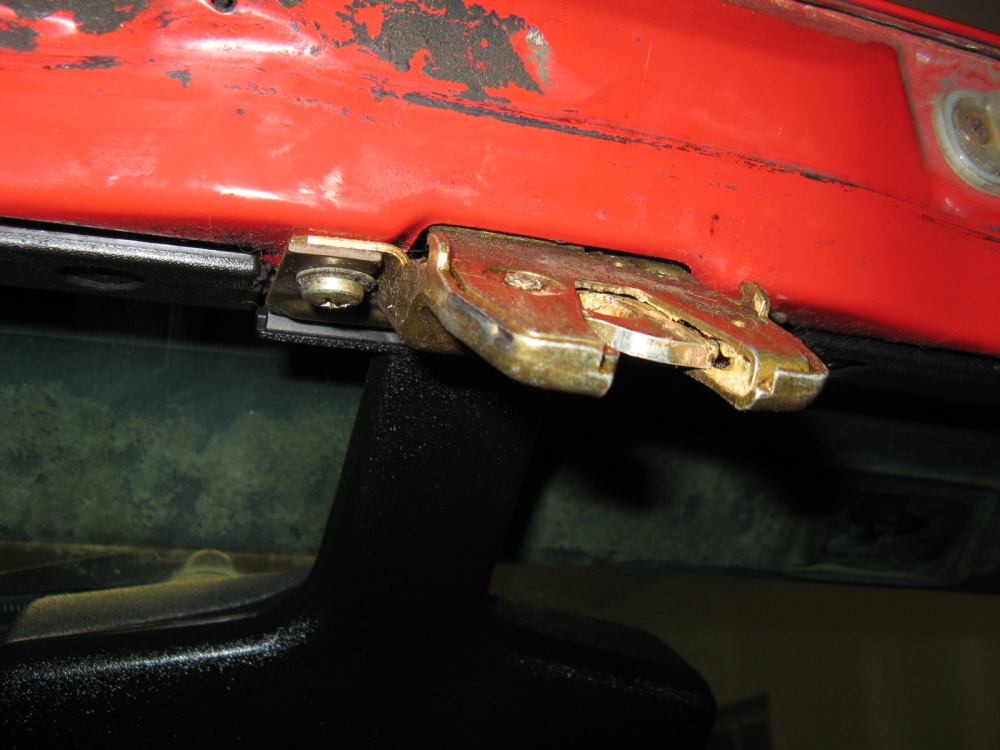
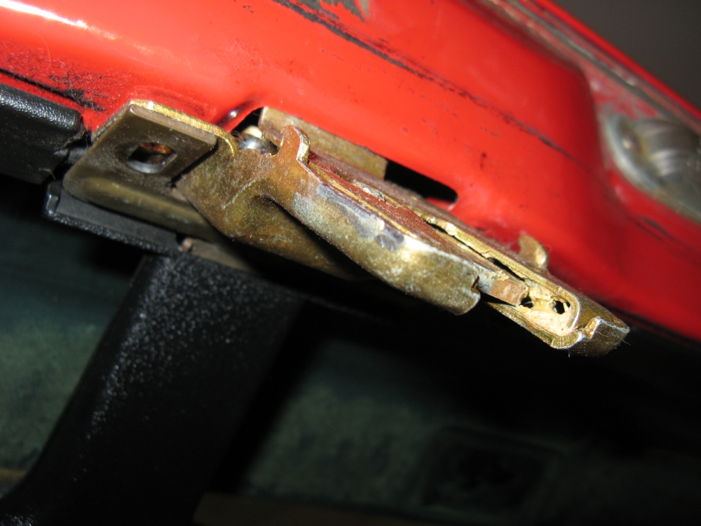
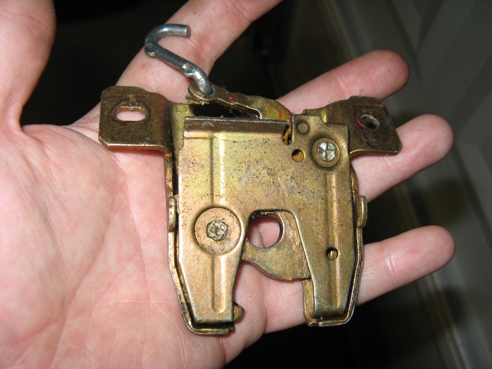
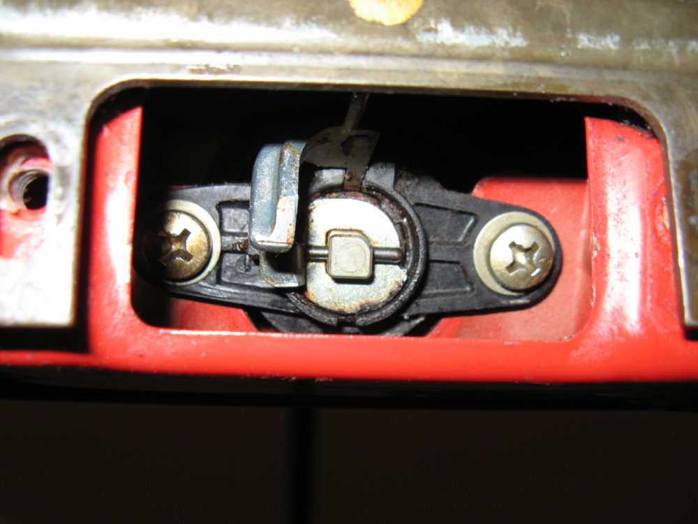
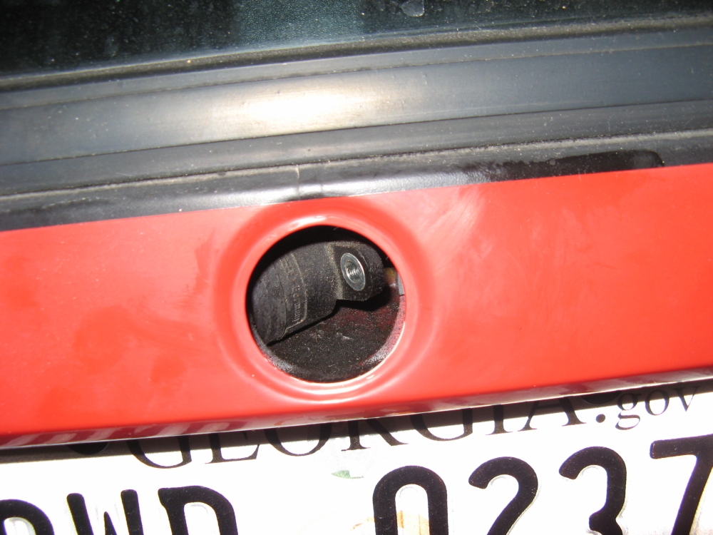
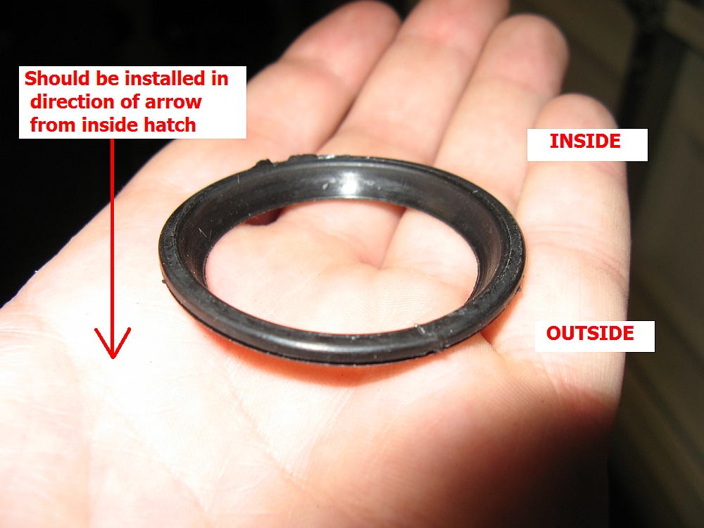
At some point in the car's history, the rear hatch lock seal had disintegrated and one of the POs had decided to caulk around it with some type of black goop.
I used some Goof-Off to remove all of the mystery black stuff so I could install the new seal. Two screws are removed inside to allow the latch mechanism to
hang down, it is hanging by the connection to the release lever. It can be unhooked from the release lever and removed. Once out, the two screws holding the
release button can be removed so that the seal can be pushed in from behind. There is a lip around the seal that should seat around the release button on the hatch
sheet metal. Once the seal is installed the release button can be pushed in from behind, it will be tight. Two screws are reinstalled for the latch button, the
latch mechanism is rehooked to the release lever, and the last two screws are reinstalled. No more leaks or aesthetic issues with mystery black goop
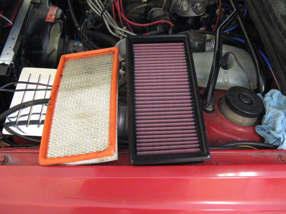
I was unsure of the old air filter condition so I decided to order a reusable S&B air filter. Similar to a K&N
or aFe, S&B makes all their products in house so they are more reasonable in price and look to be better constructed than a K&N.
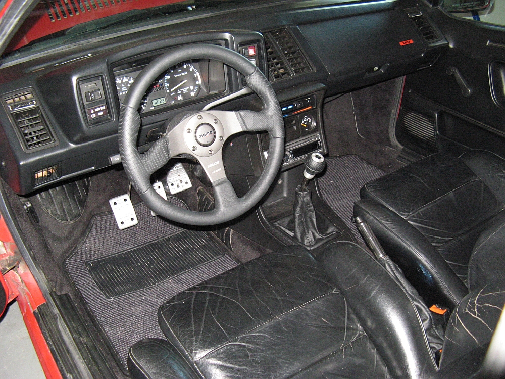
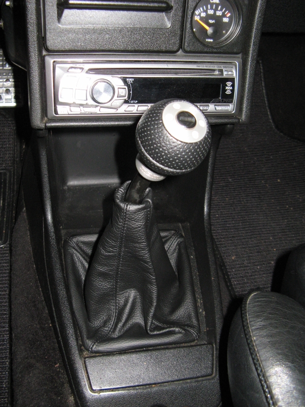
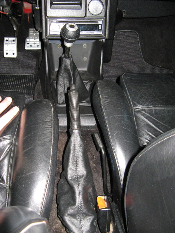
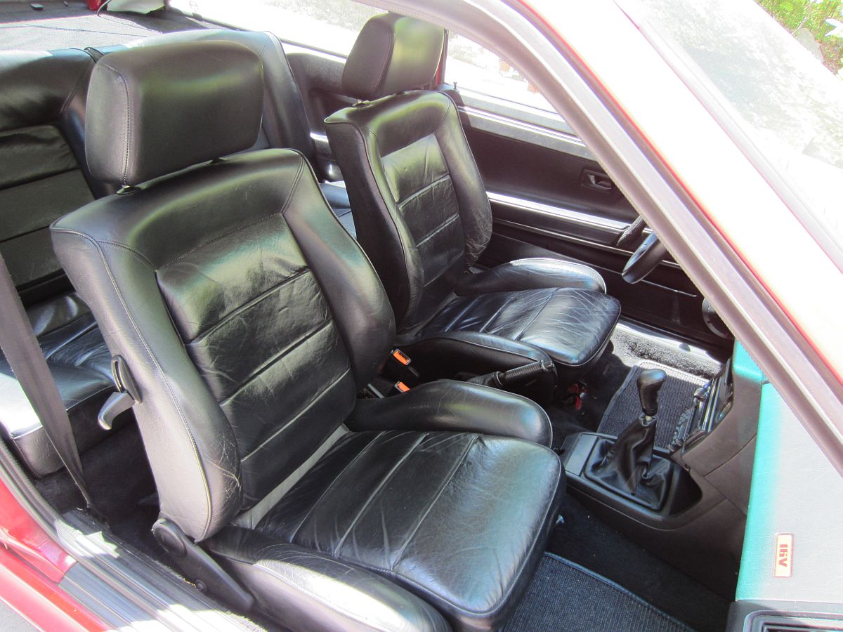
A few new interior mods and fixes. I replaced the old Momo steering wheel and shift knob with a new
Momo 320mm Race steering wheel and Race shift knob- the new steering wheel is a bit smaller
and makes it easier to slide between the wheel and seat to get in the car.
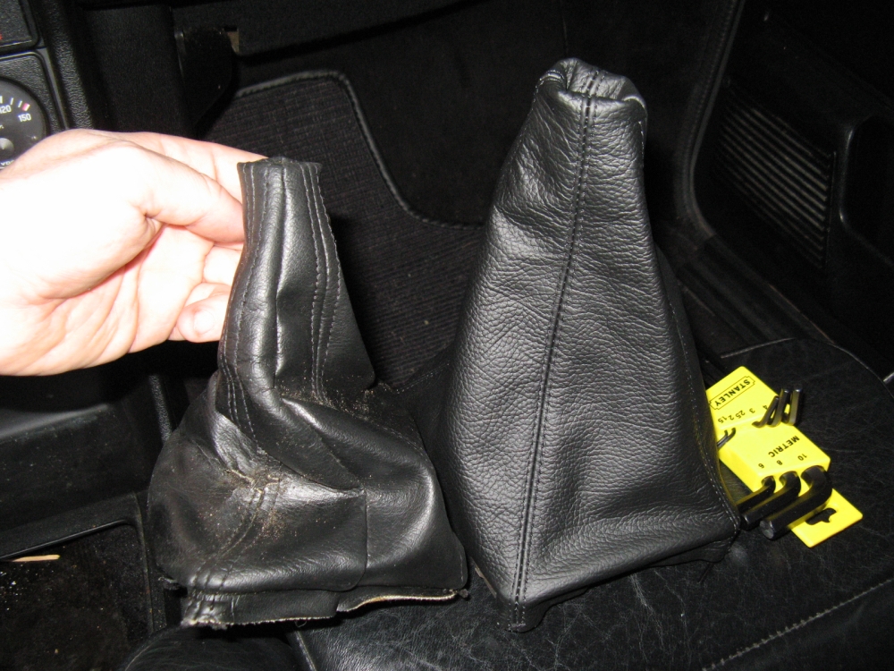
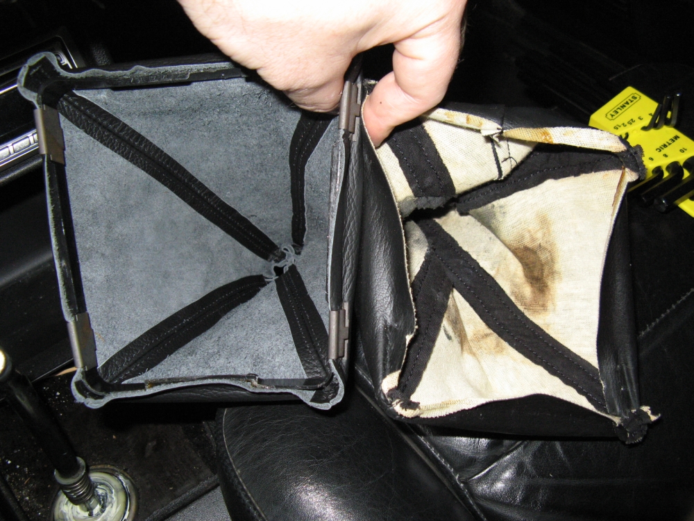
The new leather boots were sourced from Redline Goods, I have ordered their boots for previous cars
and have always been impressed with the quality and fitment. The four clips and plastic ring from the OE shift boot have to be reused, the parking brake
boot has elastic around the bottom to stretch fit over the plastic base. The shift boot clips are removed by lifting the clip inside the boot and pulling off with
the boot.
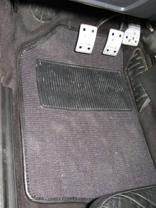
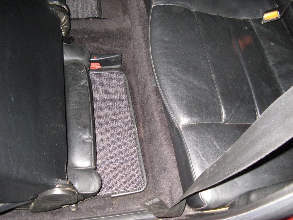
Coco Mats Sisal mats installed to replace missing and worn OE mats. These mats are superior in every
way: thick and stable with more coverage, I'm sure they will last a long time as well. Mercedes Benz Magazine wrote an article about the company
HERE.
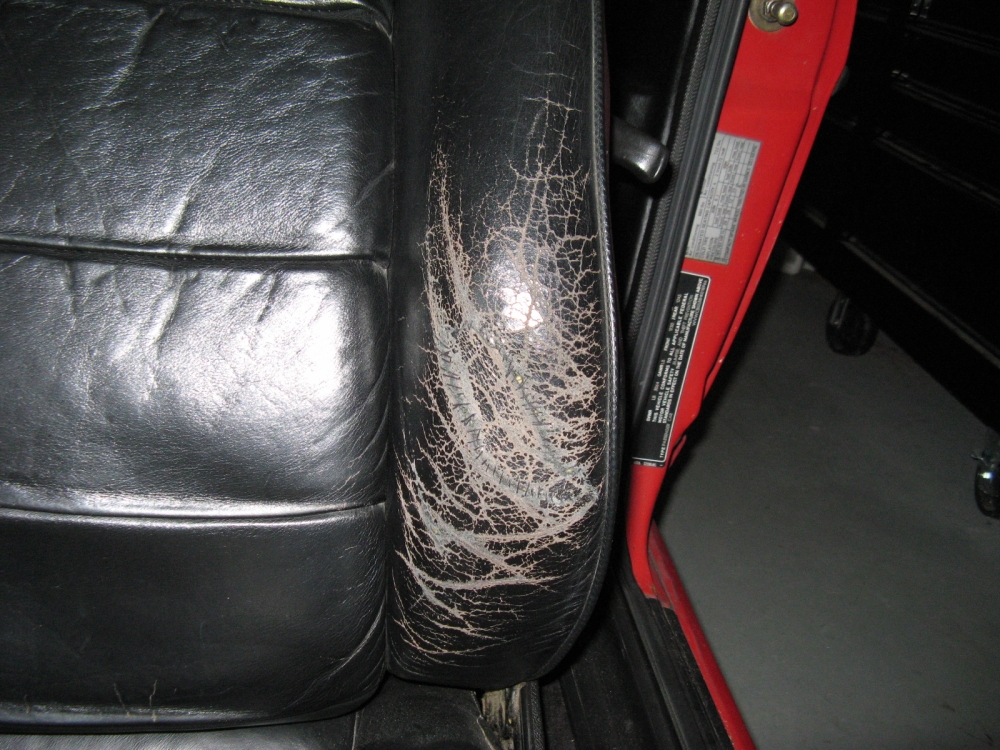
I also stitched the leather on the drivers side bolster back together until I can find someone to recover the seat, and used some SEM black dye to make it look
better- once dry leather conditioner was used to soften the dry leather.
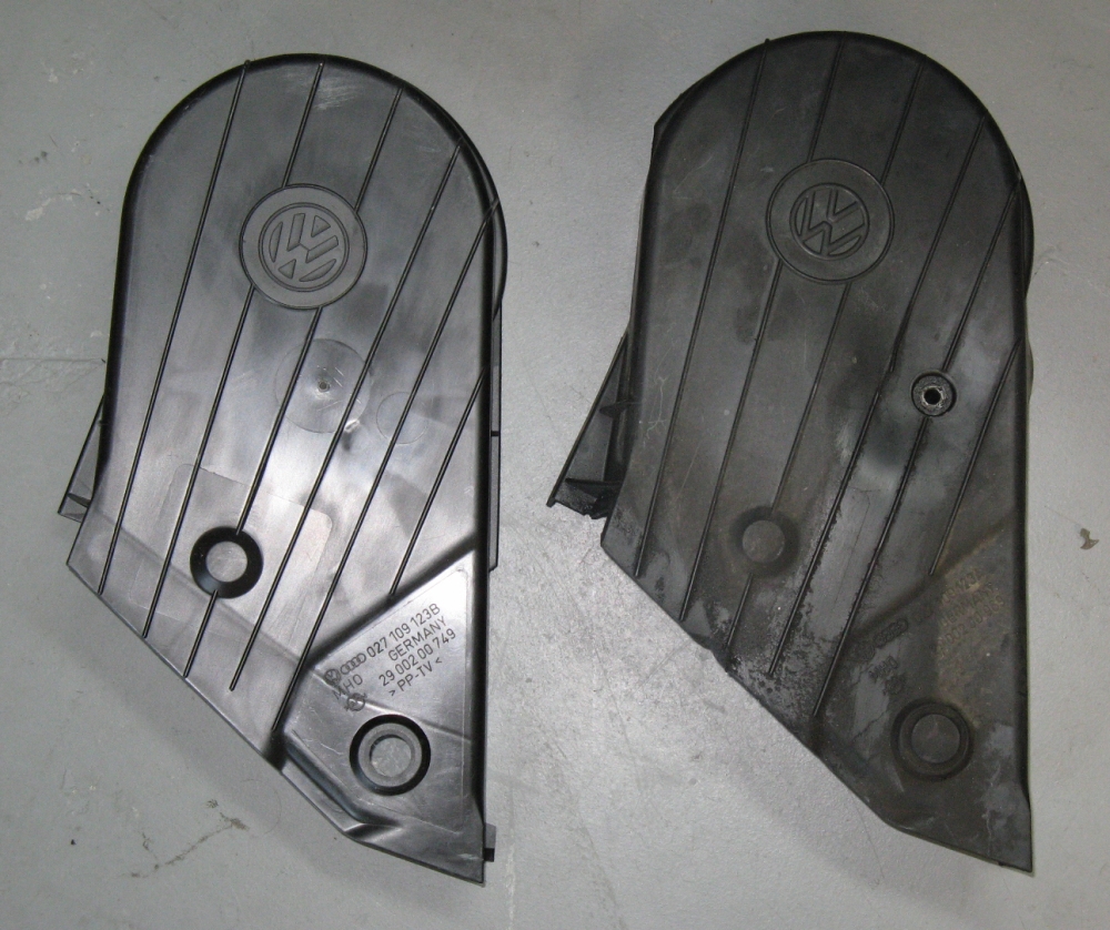
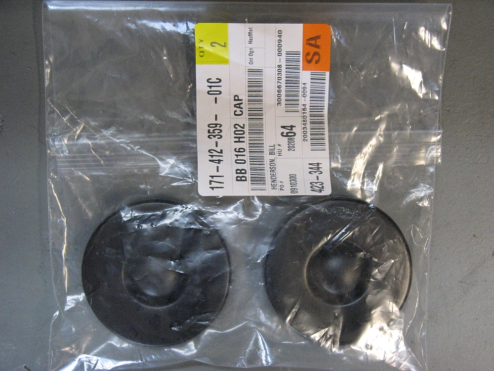
Some new plastic engine parts sourced from 1st VW Parts. The strut tower caps were cracked and loosely attached
when I bought the car and the upper timing belt cover had warped so that it was not effectively covering the timing belt on one side. It seems the new
upper timing belt cover was revised to clip to the motor up front in place of the hex bolt/washer that had been used in the OE piece. The upper timing
belt cover is part number 027109123B and the strut caps are part number 17141235901C:
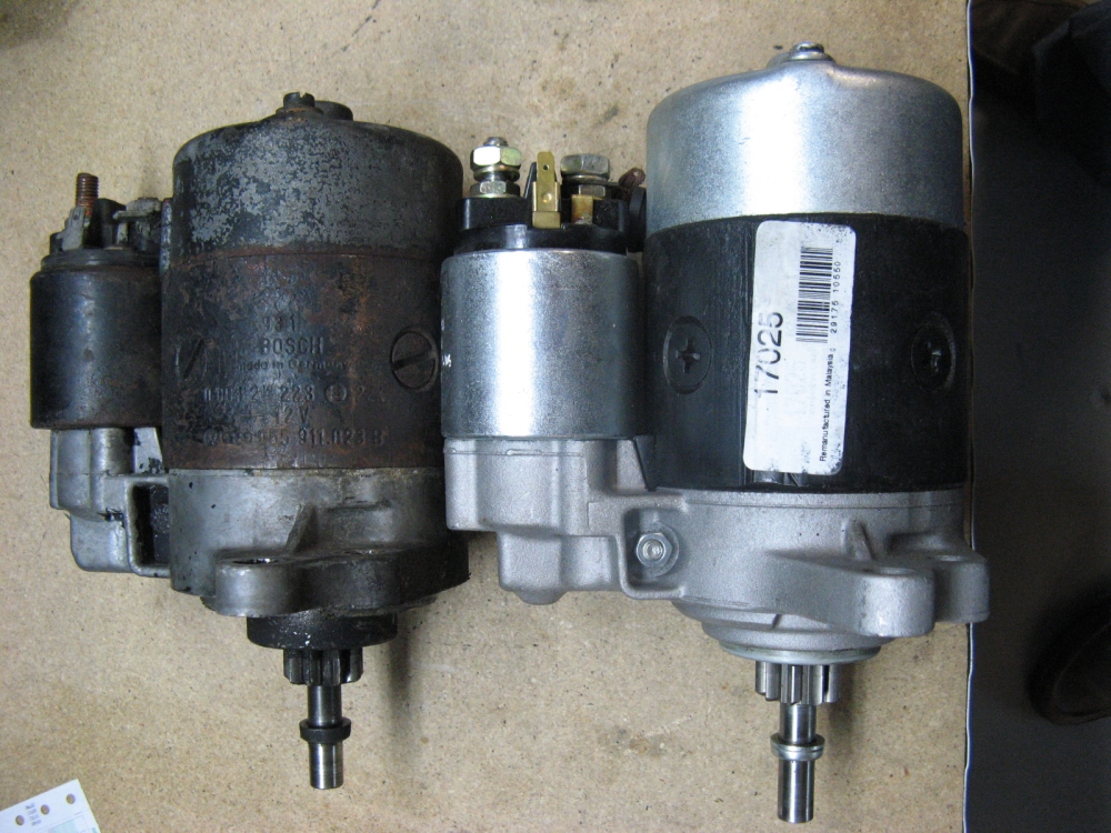
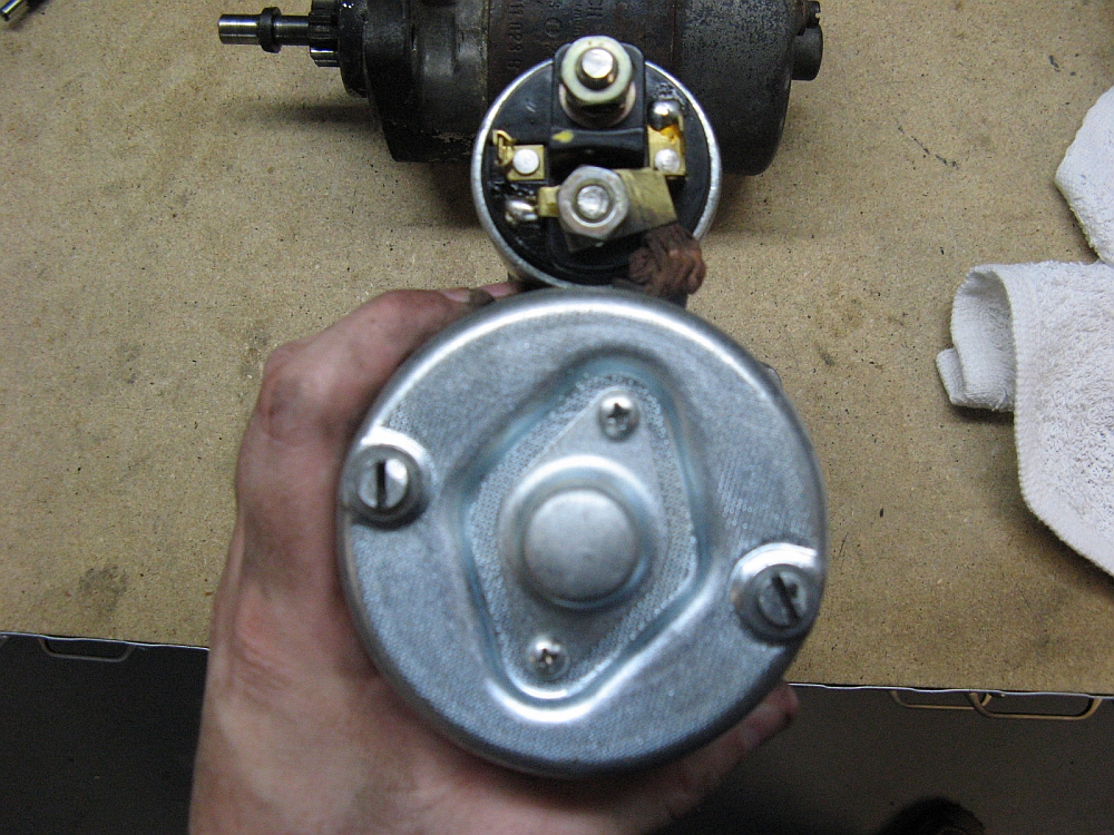
The car had been failing to crank, what started out as slow cranks soon turned into the starter not turning the motor over- as soon as the starter engaged
it would suck the battery dry. This was the original starter and I figured that internal parts may be worn to the point that a short was occuring under load, I knew
the battery and alternator were fine. I decided on an O'Reilly Auto Parts
remanufactured starter; the price was competitive, it has a limited lifetime warranty, and it is the only McParts store in town with knowledgable counter
staff.
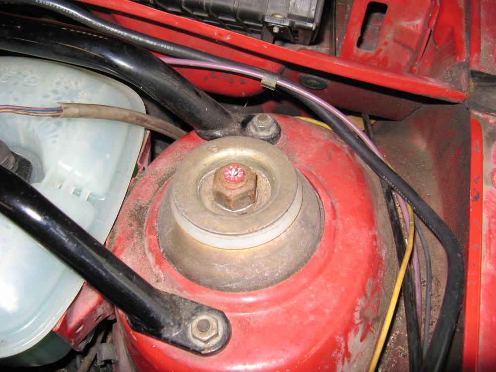
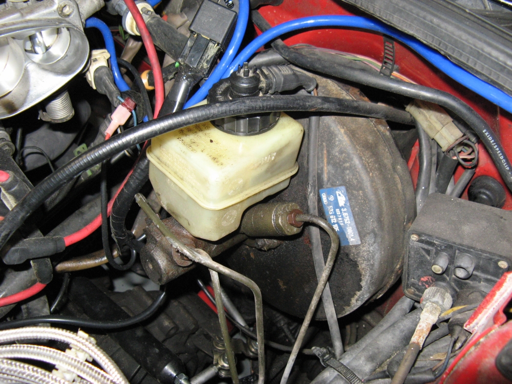
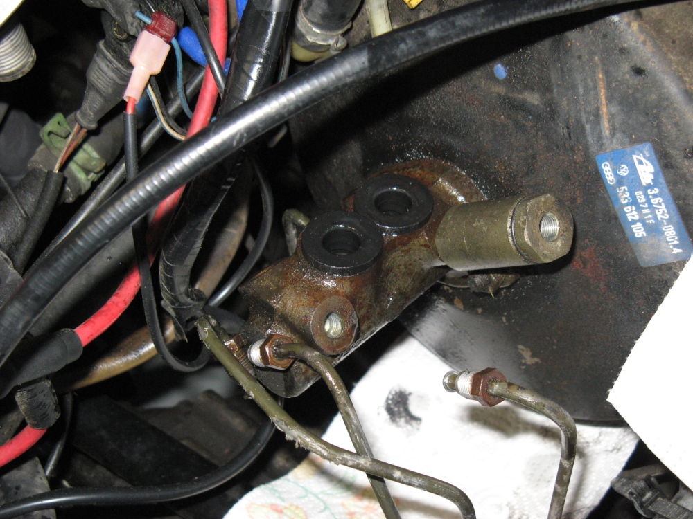
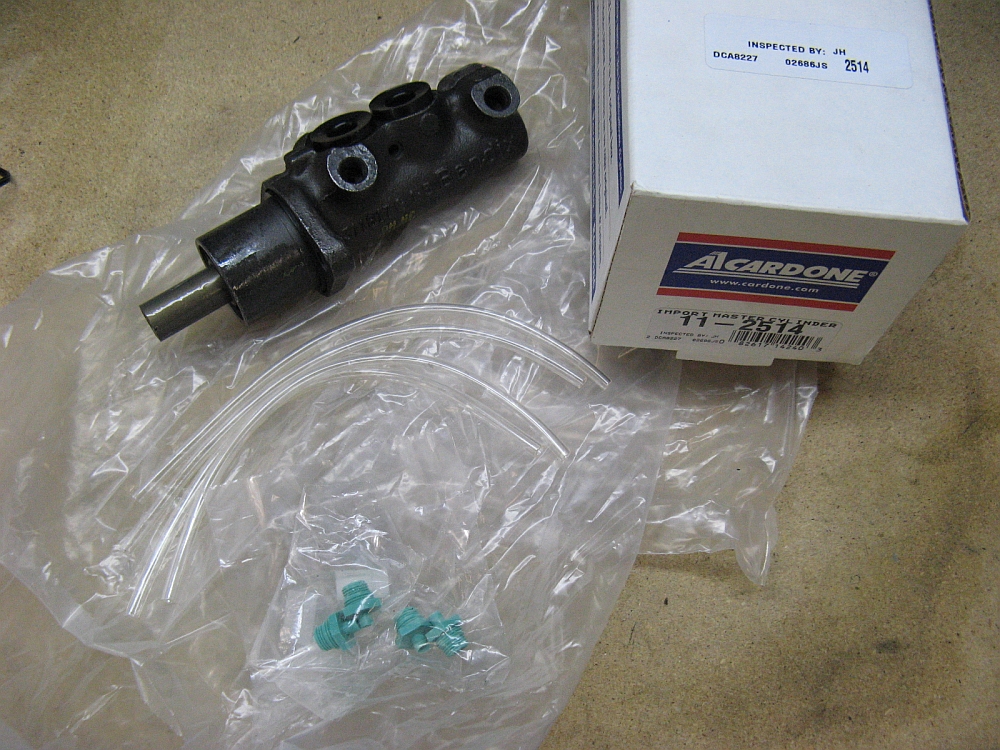
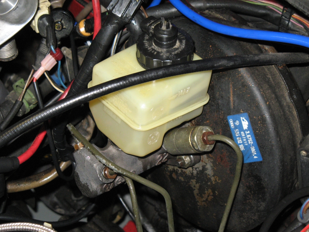
I found that the car was leaking brake fluid, it was dripping down and collecting around the brake line grommet and dripping on the ground. I figured it might be
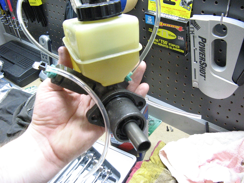
a bad brake line(s) but then narrowed it down to the master cylinder, the brake vacuum booster was wet. Off to the McParts store to get a new master cylinder to
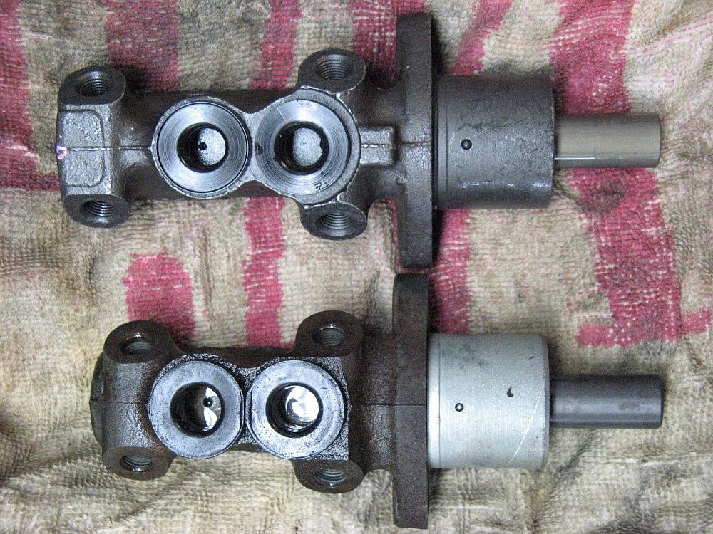
replace my original 22 year old one. The Corrado G60 (~1990 model) brake master cylinder has the same 22mm bore size as the Scirocco 16v and is MUCH cheaper,
the only difference visible is that it is a little longer but does not cause any fitment issues. My strut brace was removed for access to the master cylinder
and the coolant reservoir was temporarily moved to the side as well. [WARNING] BRAKE FLUID is NOT GOOD FOR YOUR PAINT SO BE CAREFUL!!
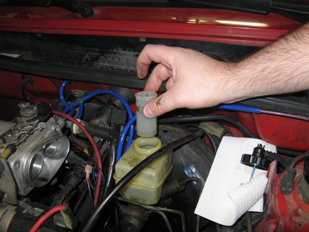
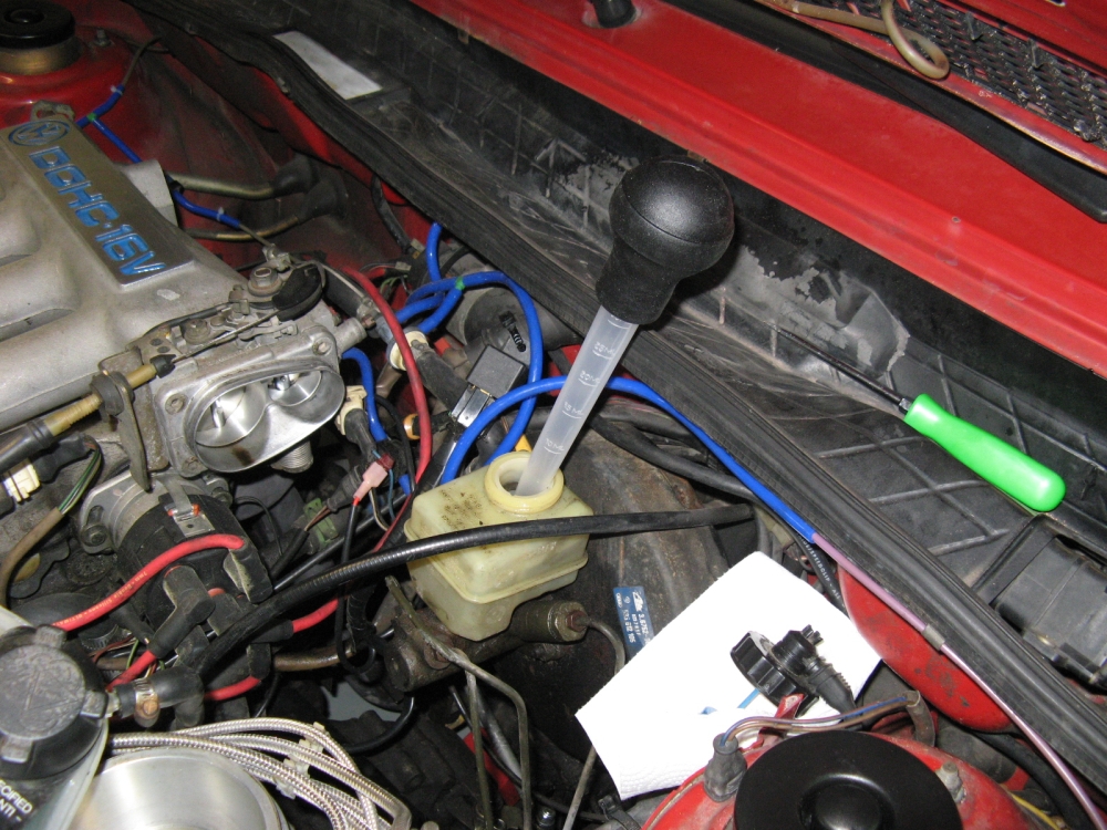
The MC reservoir plastic trap is removed by turning and pulling up and the master cylinder reservoir is emptied using a turkey baster (old empty brake
fluid containers work great for storing the old fluid as the turkey baster is cycled a few times). The reservoir is then removed by pulling up and out of
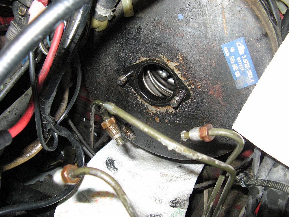
the master cylinder seals, be careful because this will be re-used. The brake lines can then be disconnected using an 11mm flare wrench (not a standard
wrench that might round the edges off of the brake line nuts). After the lines are disconnected two bolts holding the master cylinder to the brake booster
are removed and then the master cylinder is free.....until it gets dropped in the core return box anyway
Timbo also has a master cylinder R&R write-up HERE that is helpful.
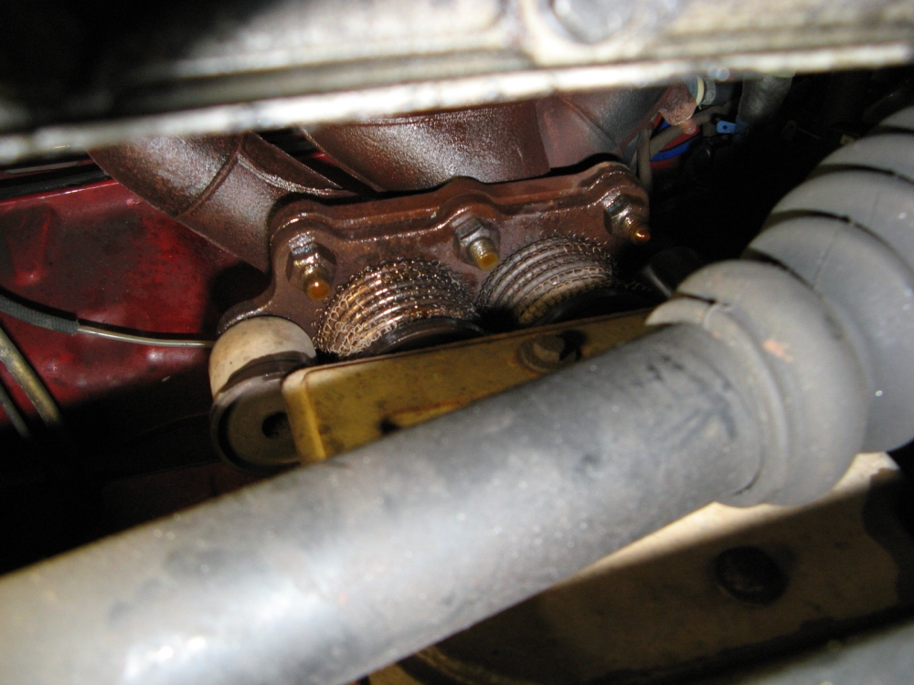
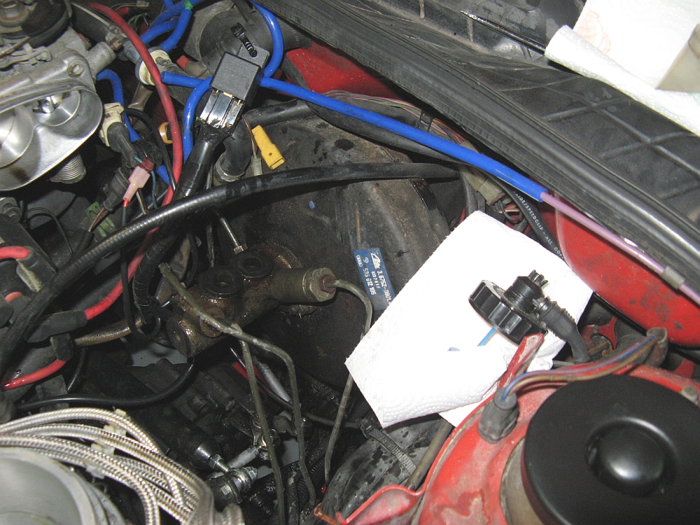
Well, the brake fluid leak continued but maybe a little less. The culprit is the O-ring seal on the proportioning valve attached to the master cylinder, the
other proportioning valve was fine. After trying to source new proportioning valves I gave up......almost. New proportioning valves for a 16v Scirocco were not only impossible to find,
but would have been $$$$ if I had.
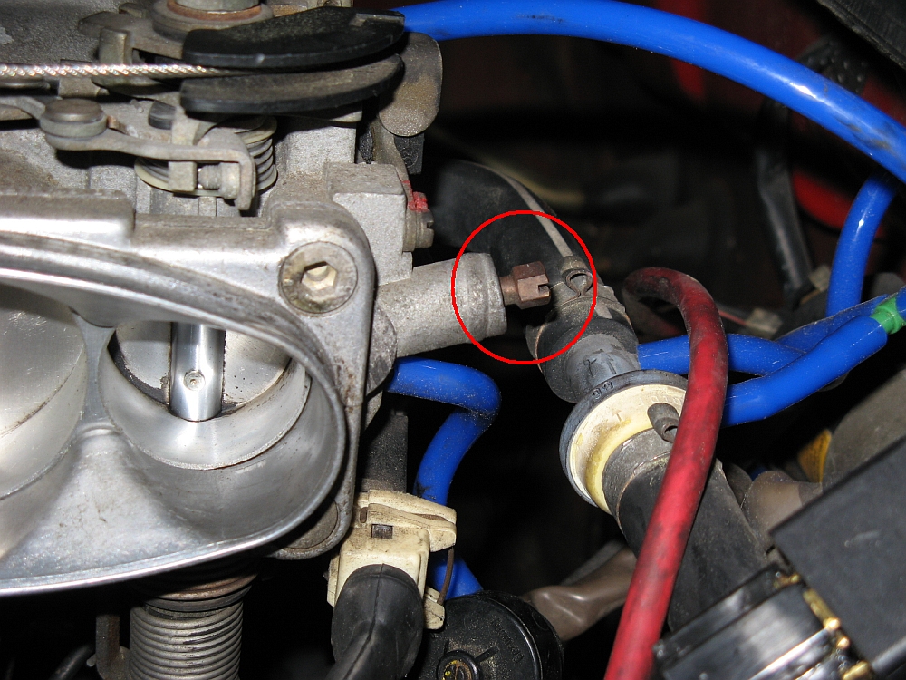
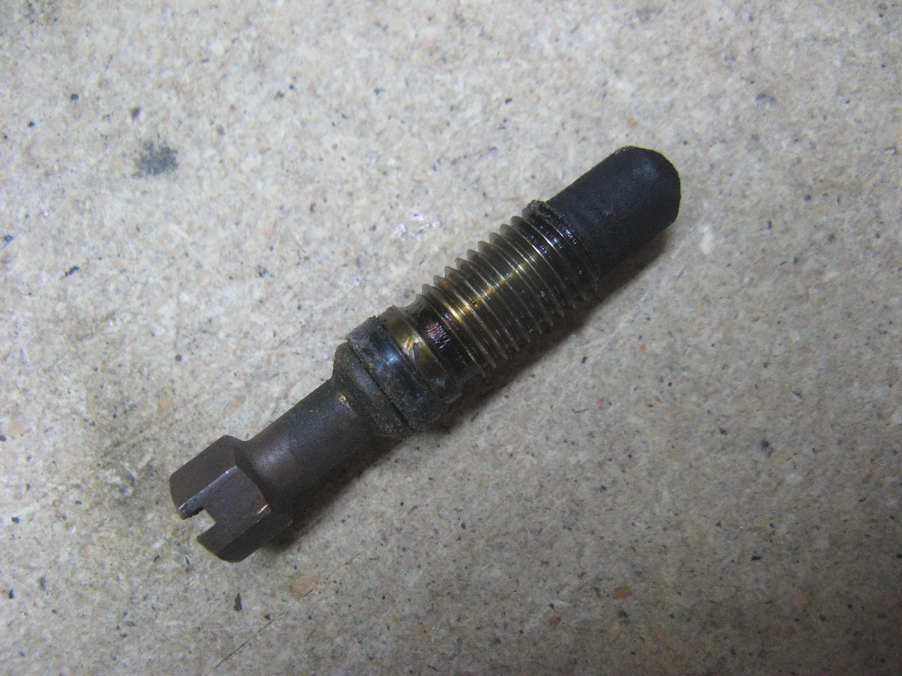
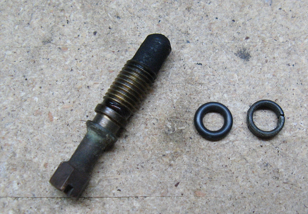
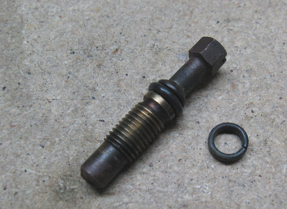
My idle speed seemed to fluctuate at times, even after setting the air/fuel ratio and correcting all the vacuum leaks. As it turns out I still had a vacuum
leak at the idle adjustment screw. The original o-ring was like plastic; hard, brittle, and flat. The o-rings used in this application are Viton, I sourced a
few from ebay vendor moogie2498 (aka MK1 Autohaus). After replacing this,
I had to readjust the air/fuel ratio by almost a full turn counter-clockwise. Idle is more stable now and car gets better gas mileage-simple, cheap fix:
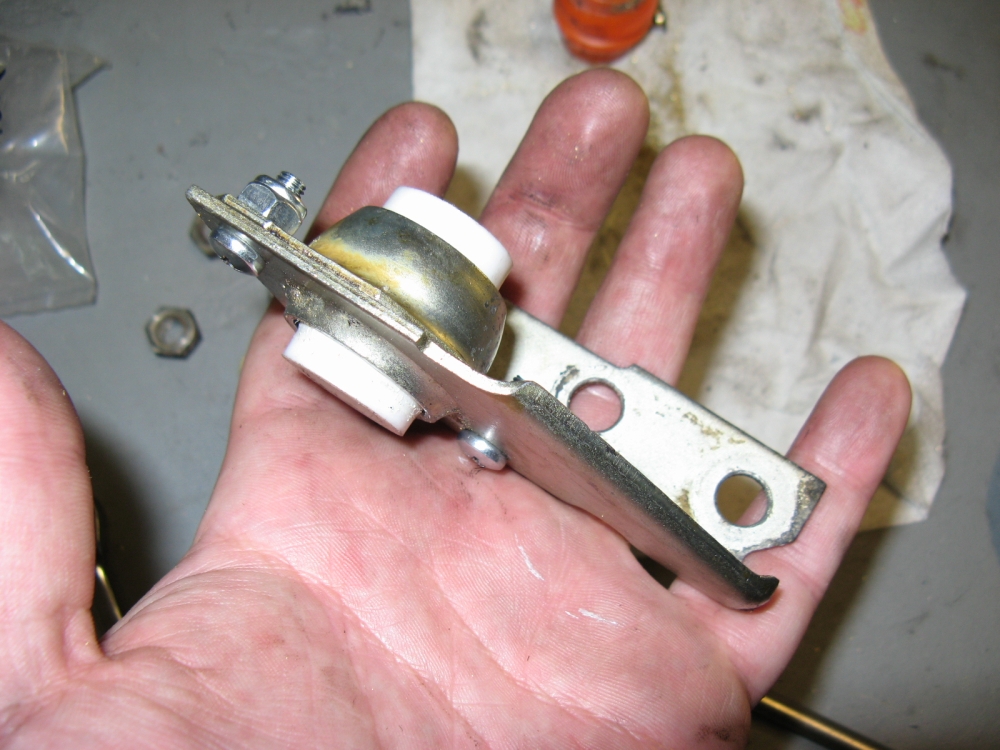
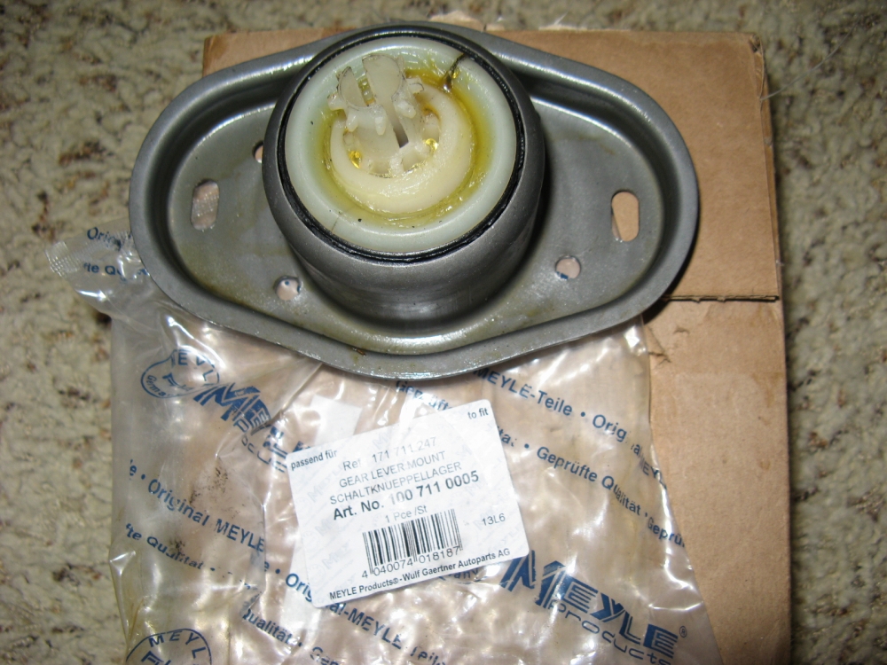
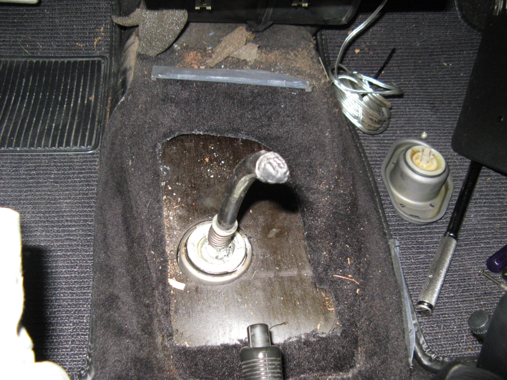
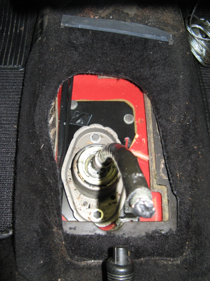
All of the shifter components had been replaced except for one, the gear lever mount, and I still had a little bit of slop. Surprisingly, nothing better than the OE piece exists
so that is what I was forced to R&R, and I'm not sure it was a huge improvement over the original item. See the OE piece slop in the video
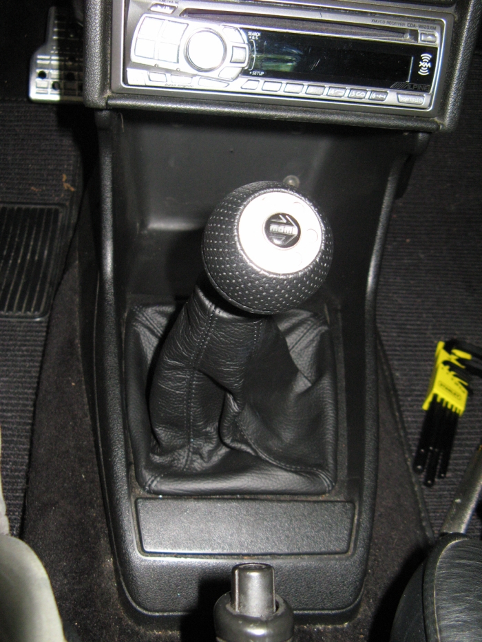
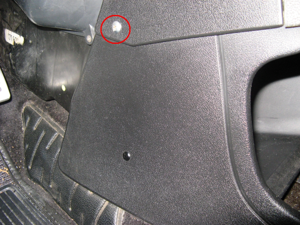
HERE. In order to replace the gear lever mount, the lower console will have to be removed-
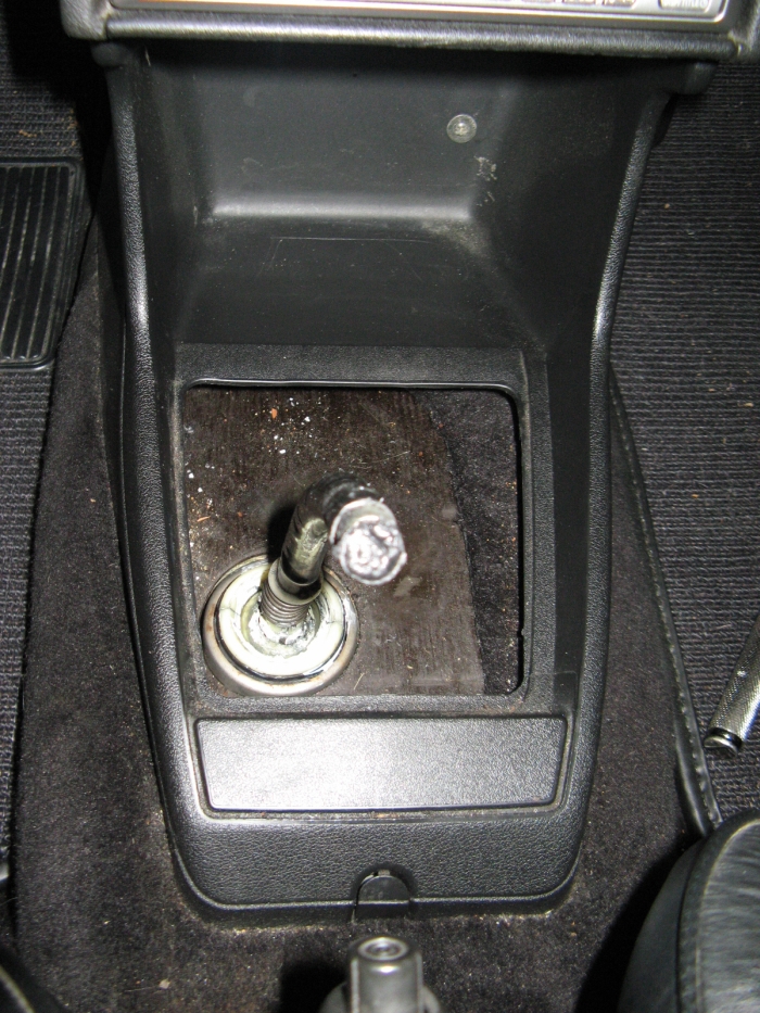
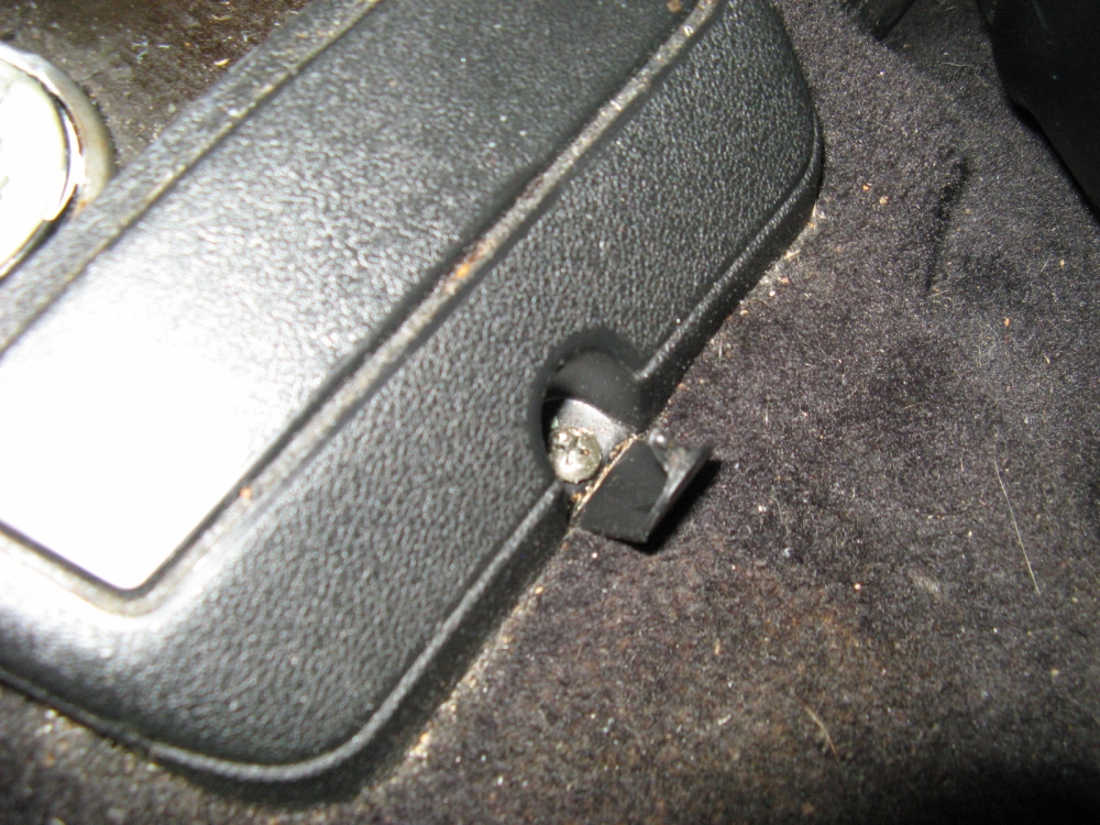
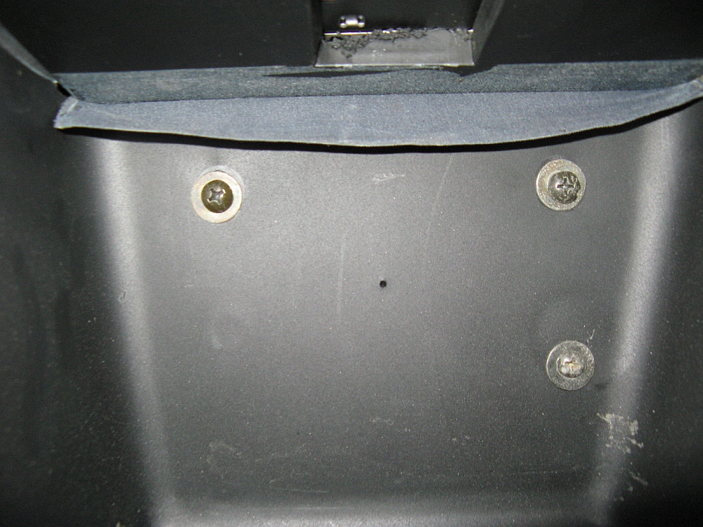
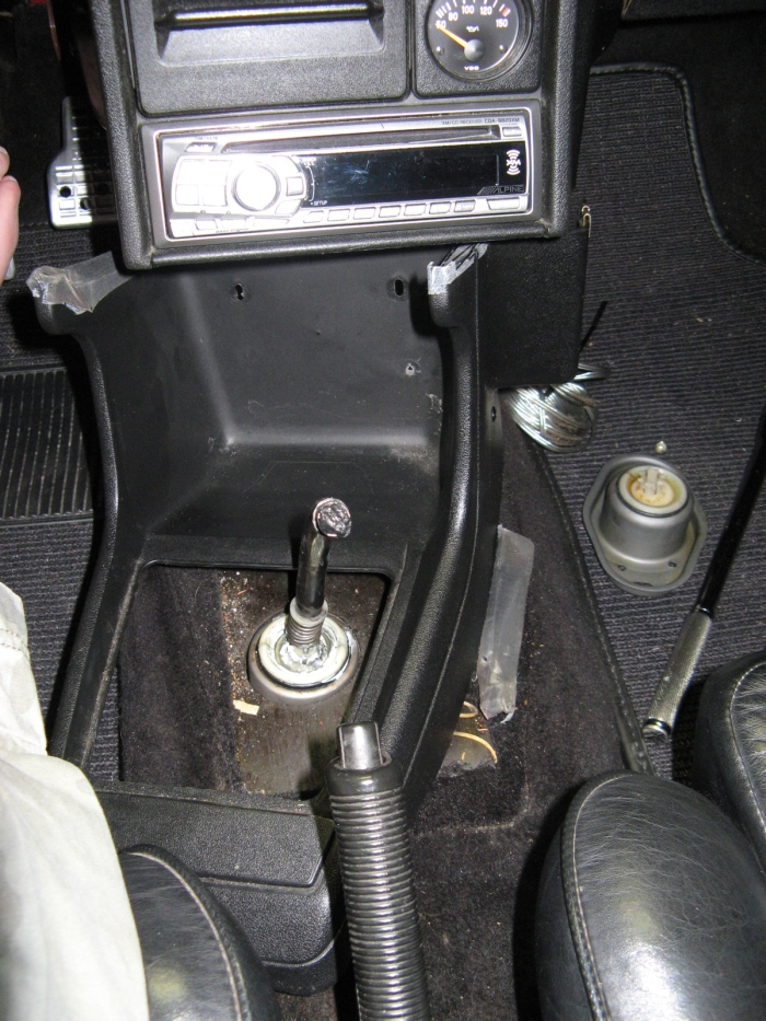
shift knob and boot removed, a few screws on either side, single screw at rear of console under plastic piece, three screws in the back of the cubby....and then the puzzle of how this thing comes out without breaking it. A little twisting and
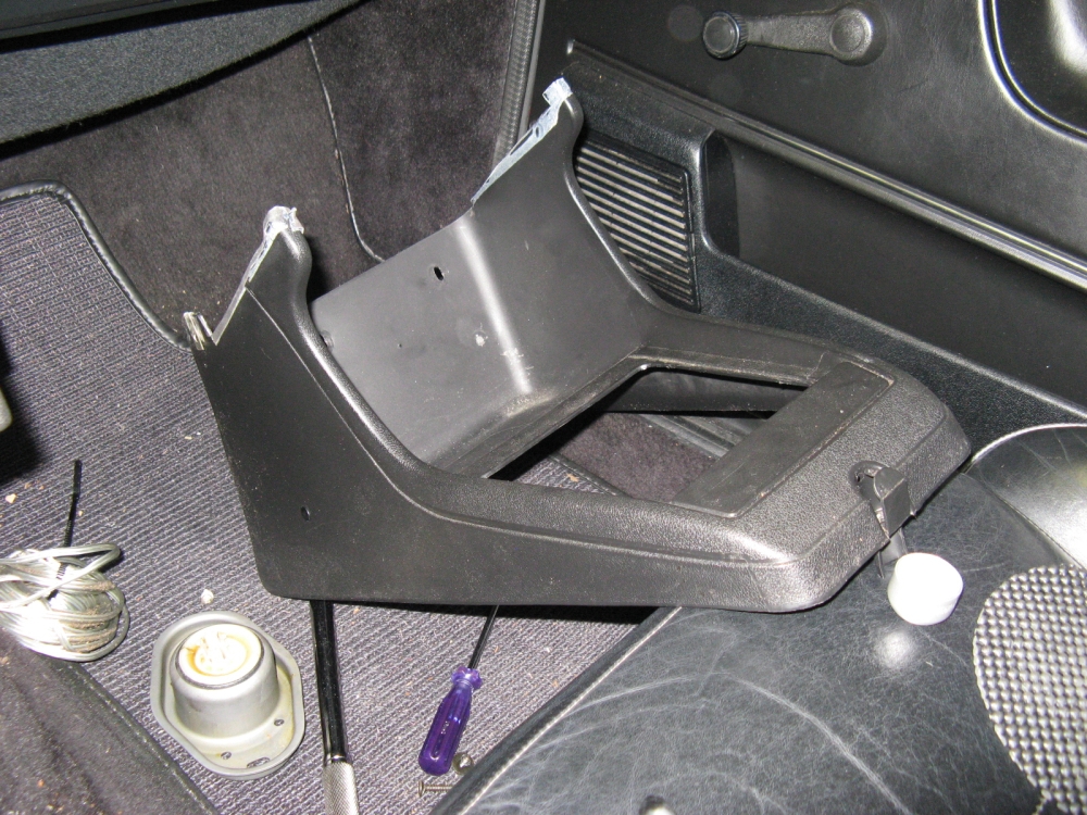
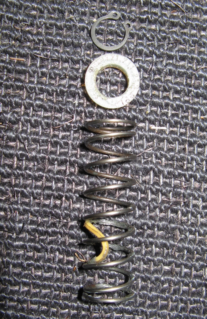
flexing and it will pop right out. After the console is out the shifter insulation pieces are removed to gain access to the two gear lever mount screws. The retaining
spring is held in place with a snap ring, snap ring pliers make quick work of this. The plastic piece on the shifter rod has to be removed if you have one (I left
this piece off when reassembling). The gear lever mount can now be removed by pulling up/off the shifter rod. Installation is reverse of removal:
Just when you think you might have some vacation from repairs, the odometer dies. Not a big surprise as I have had other European cars with VDO speedometers
that had the infamous gear slip (wonder why the German engineers didn't key the gear to the rod to keep it from slipping??).
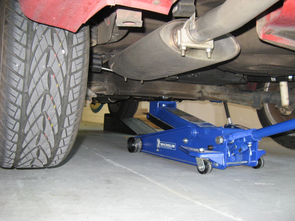
Time for transmission fluid change. I know the second owner tracked the car occasionally and was pretty religious about changing the transmission fluid (he
used Redline MTL) but I'm not sure since he sold it if it had been done or not. I drove the car up on ramps and used a jack in the middle of the rear beam
to get the car level for it to drain completely (I know, I have heard the rear beam stories but mine is still straight and car aligns fine, YMMV). I always
take the car for a drive to bring the fluid up to operating temperature prior to get all of the sludge and sediment out with the drained fluid. I have a
MetalNerd tool I used with my R32 that works great for the Scirocco too.
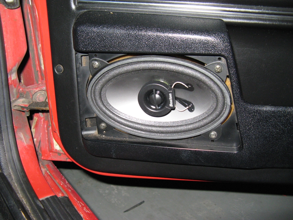
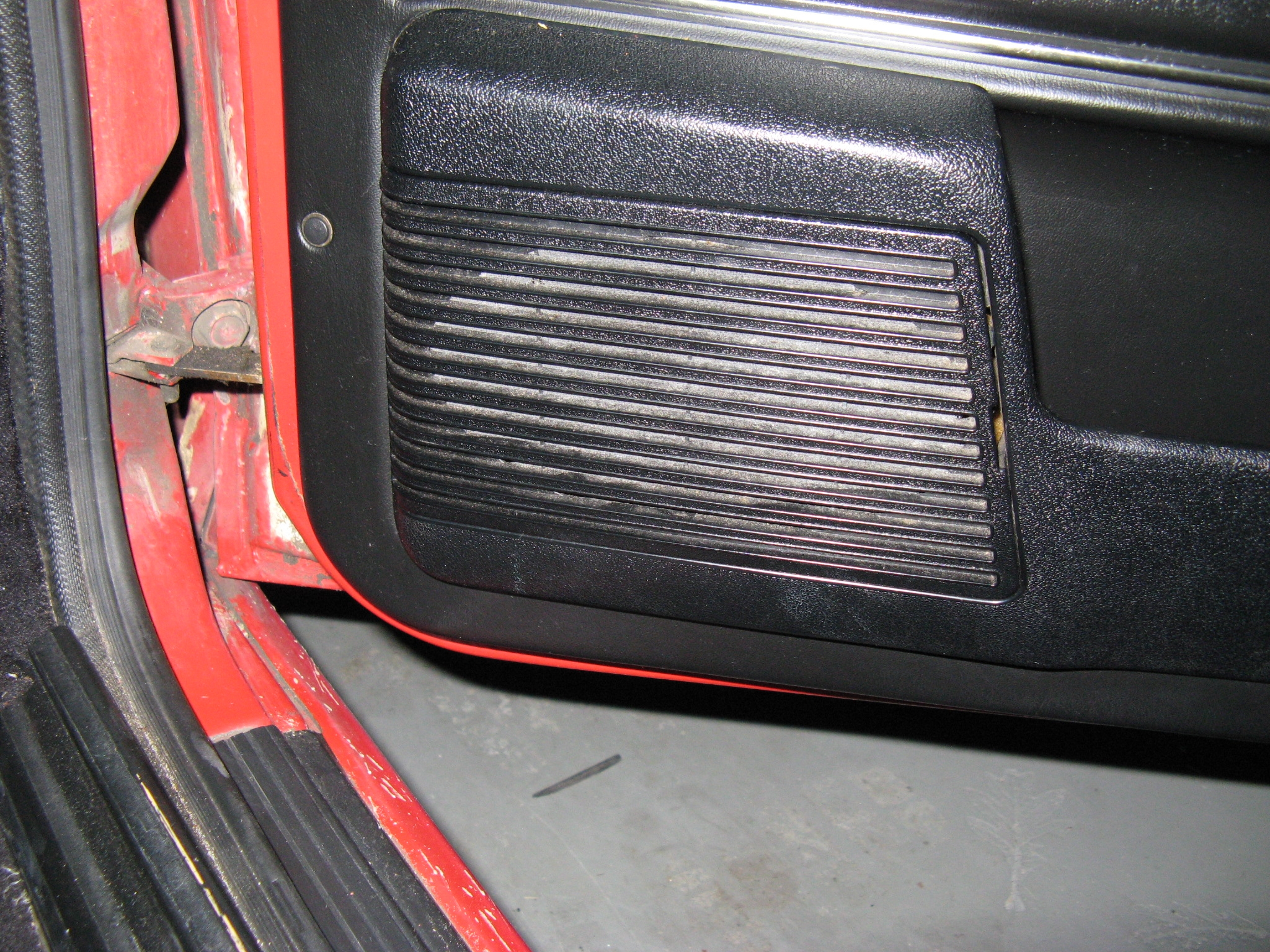
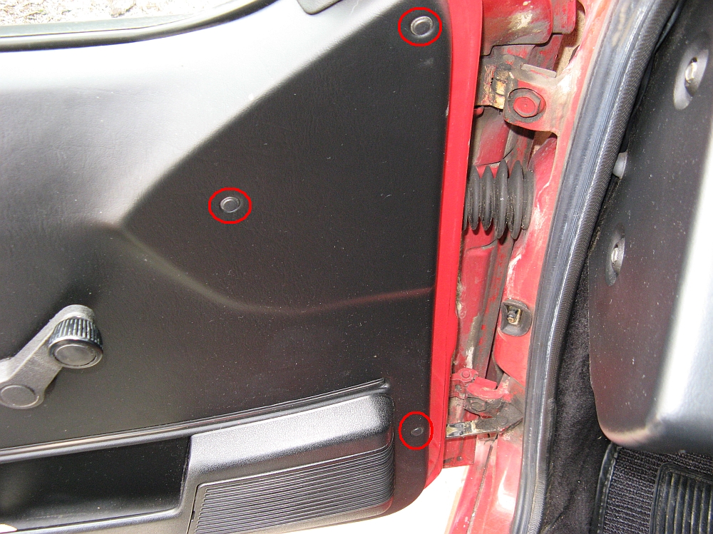
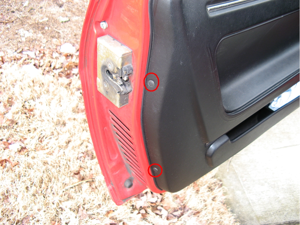
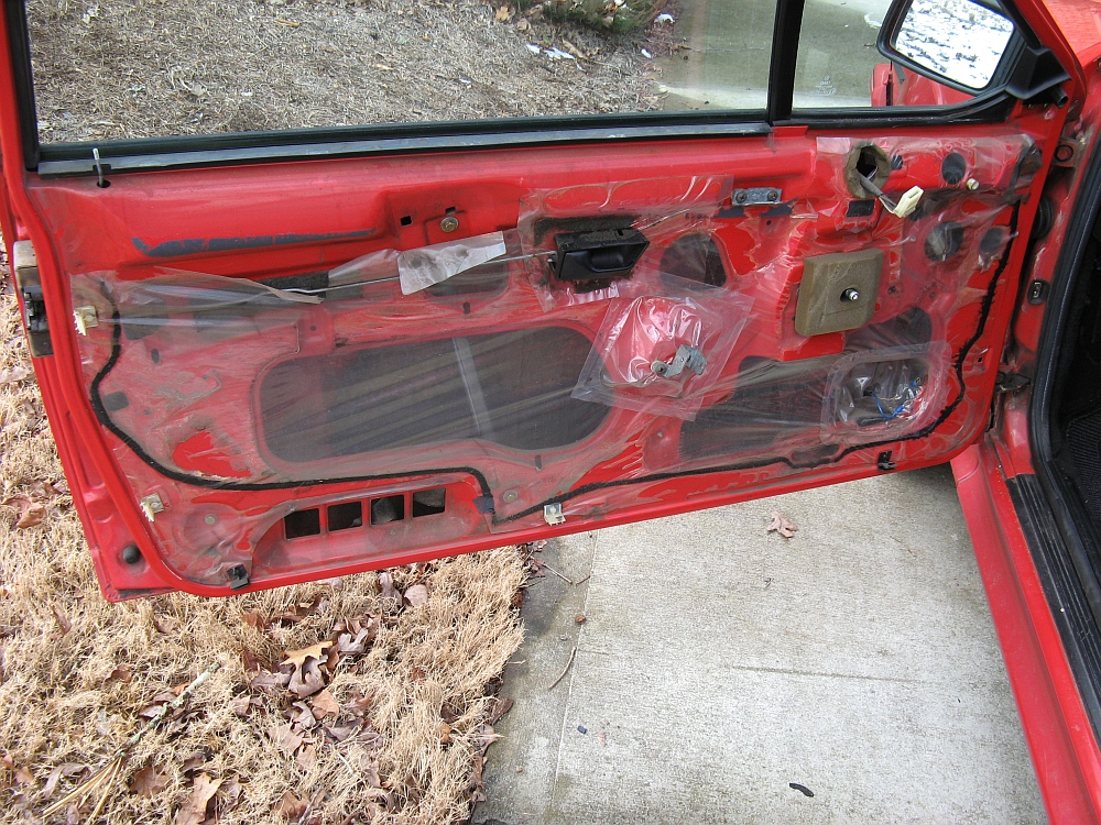
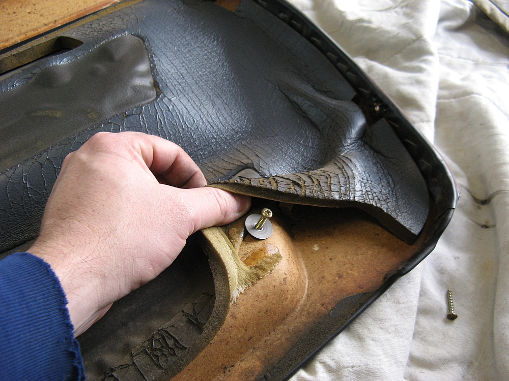
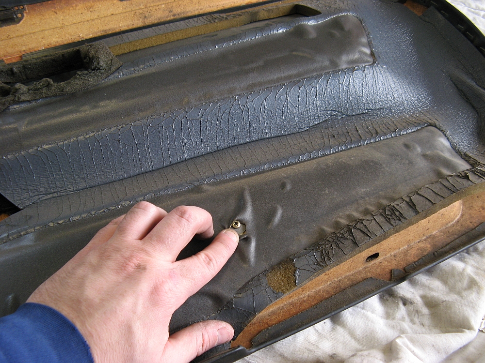
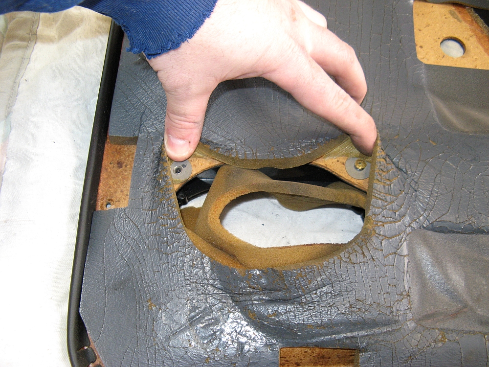
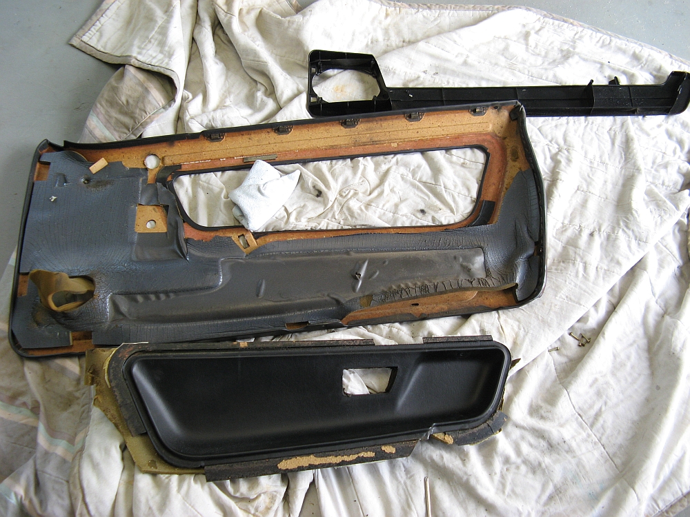
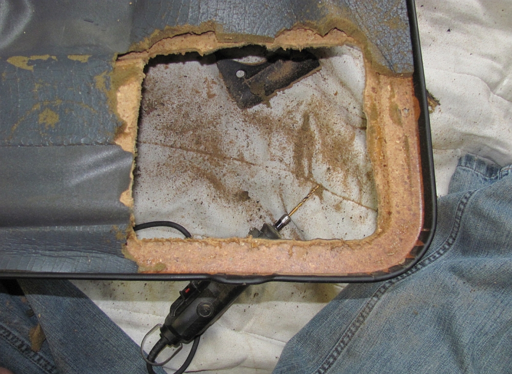
New and Improved Door Speakers: The 4x6 speakers in the rear are OK for rear fill, but having them in the front is horrible- no mids/bass. I decided to cut up my perfectly good door panels
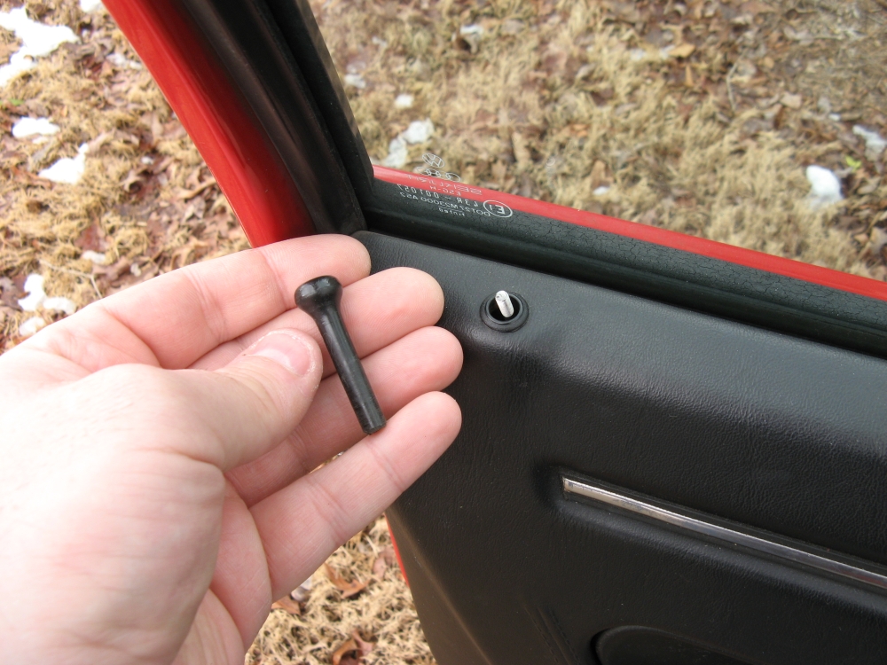
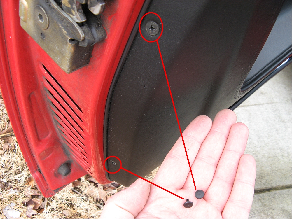
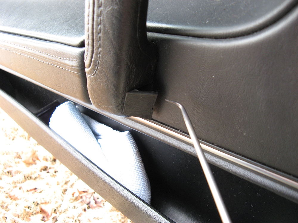
after removing the OE door pockets/speaker enclosure (screws buried under the foam on the door panel). The screws on bottom and rear edge are removed (after removing the center plastic piece that makes them look nicer
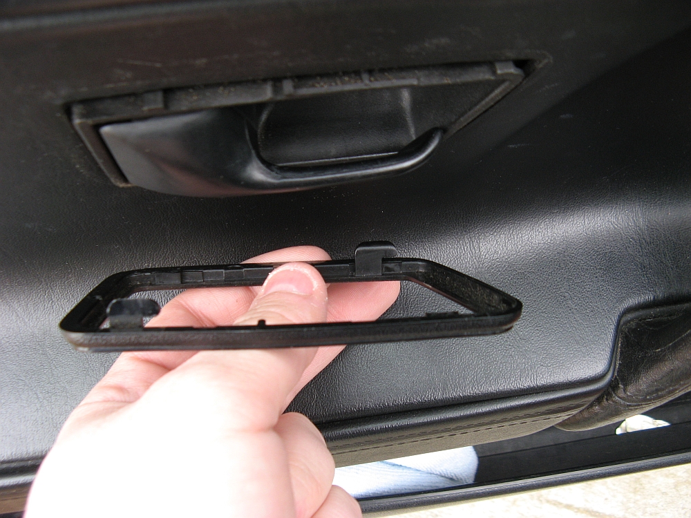
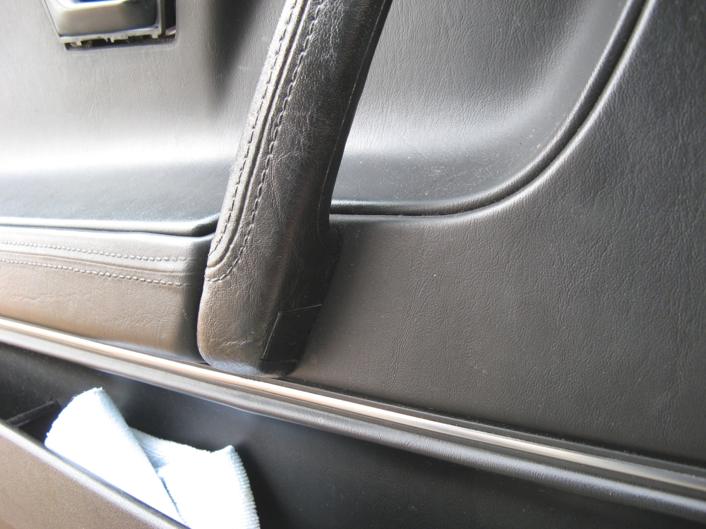
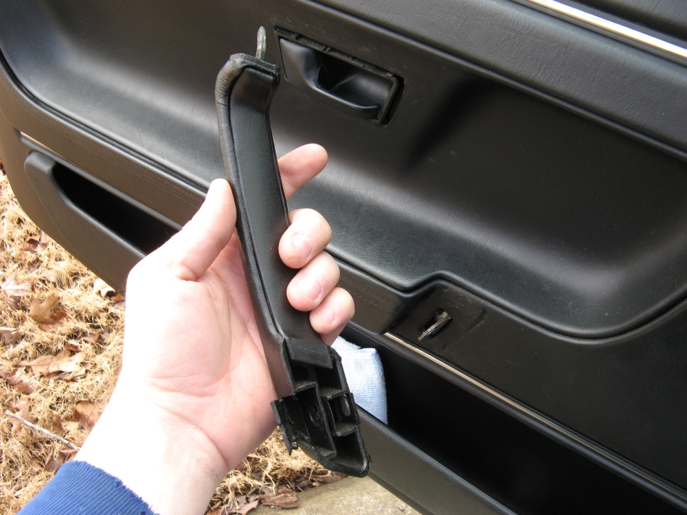
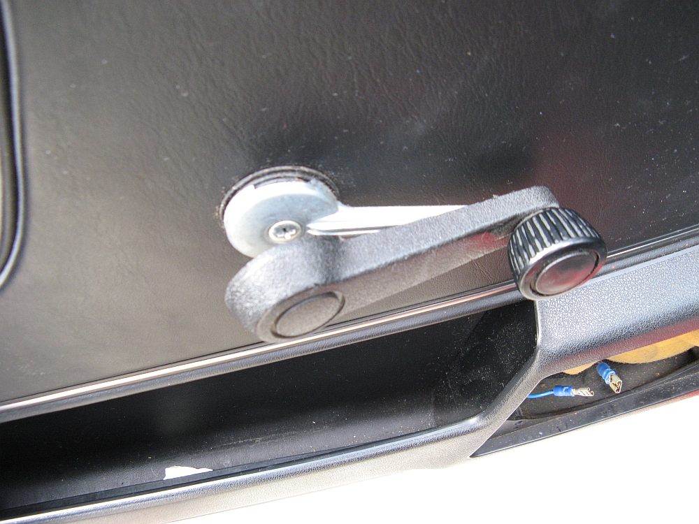
than just screws), the trim around the door latch is removed (by pushing back to unhook and pulling out), the window crank is removed (by pulling the plastic cover up to expose the Phillips head screw), the door handle is removed (by popping open the
hinged cover at the base to expose the single Phillips head screw-the top is just hooked into place), the door lock knobs are uscrewed/removed,
the rear view mirror switch is popped out and unplugged (not pictured), and the speaker cover is removed using a flat blade screwdriver so that the speaker can be unplugged and removed (4 screws).
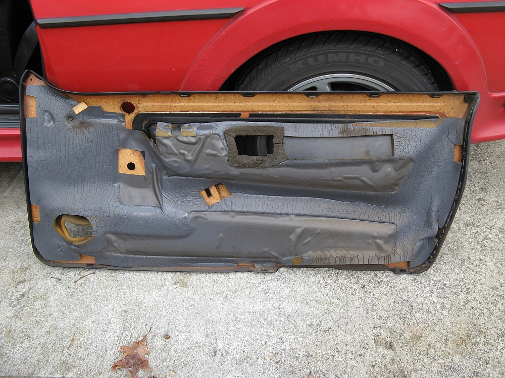
The door panel is carefully lifted over the door lock rod and pulled out of the window trim piece.
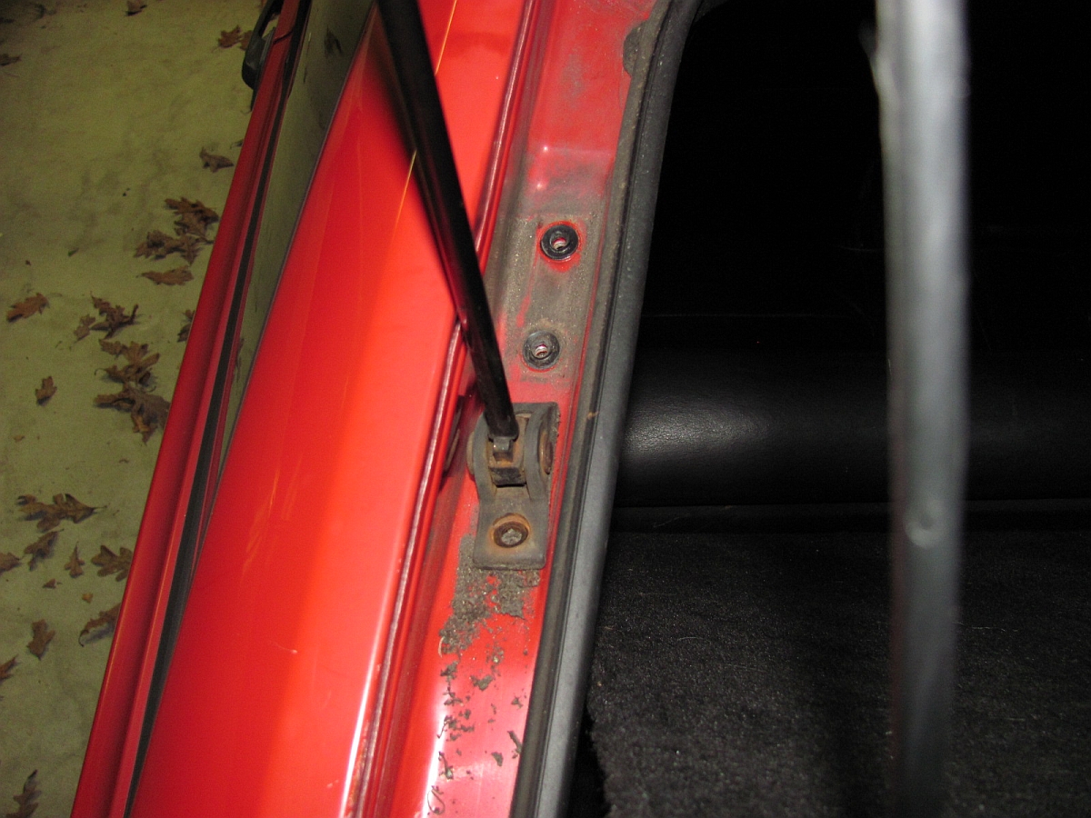
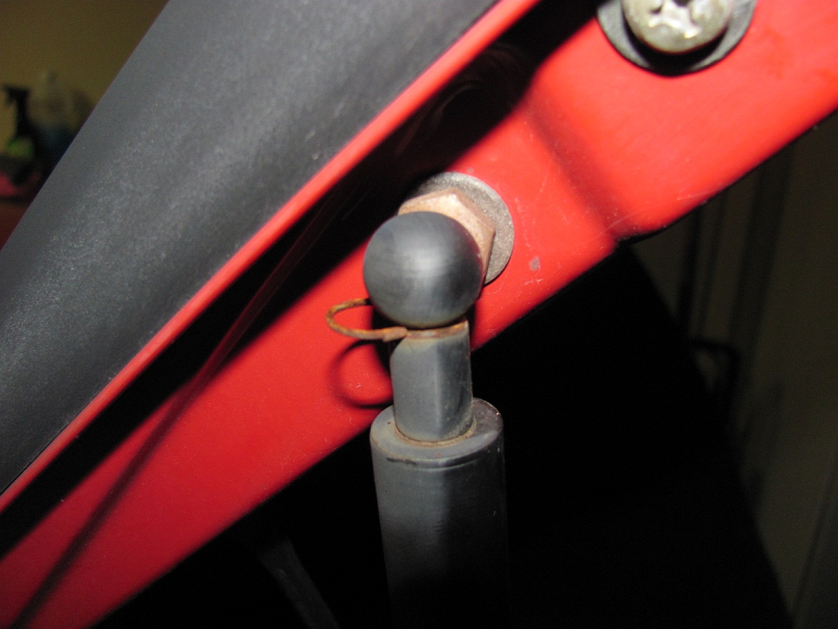
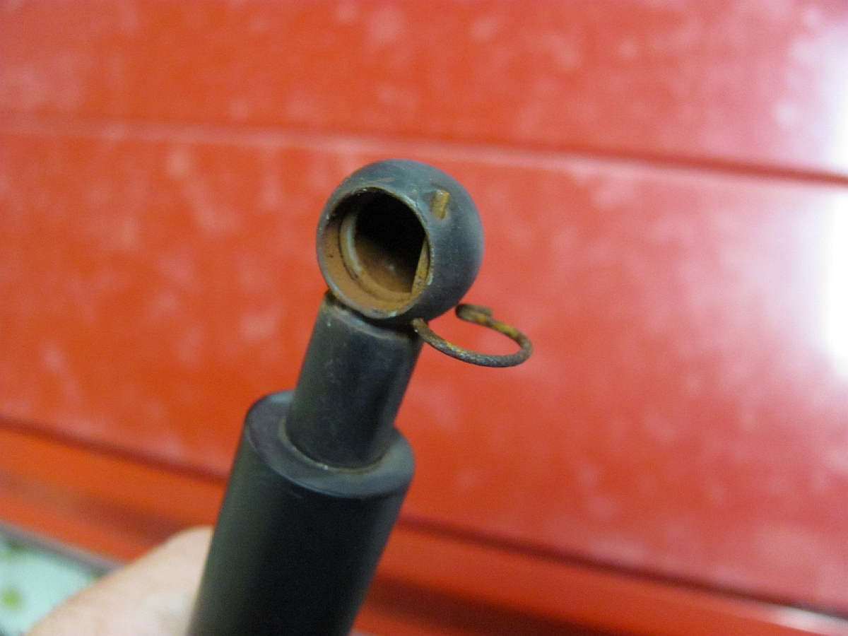
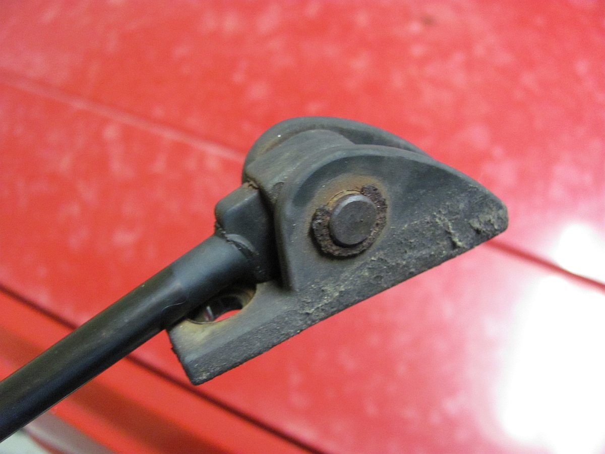
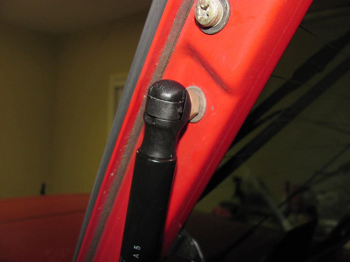
Time for new hatch struts when the hatch will not stay open, I sourced new Sachs Stabilus struts (P/N SG301002) from Rock Auto.
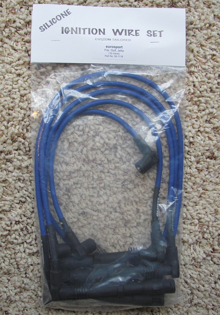
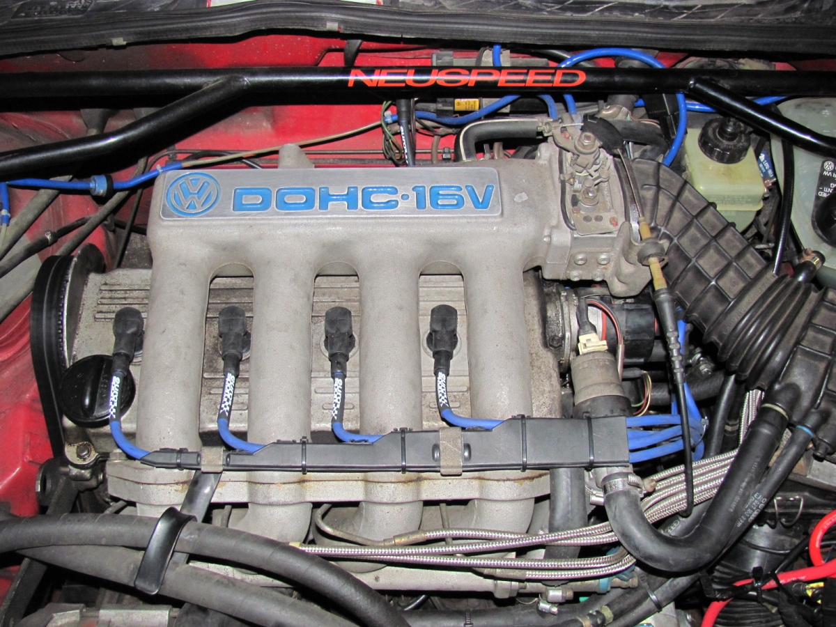
New EuroSport Accessories ignition wires. Old ones were out of spec, these are performance oriented wires with a lifetime warranty. Sourced from Supreme Power.
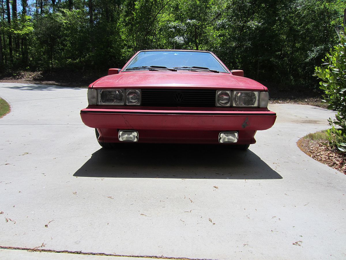
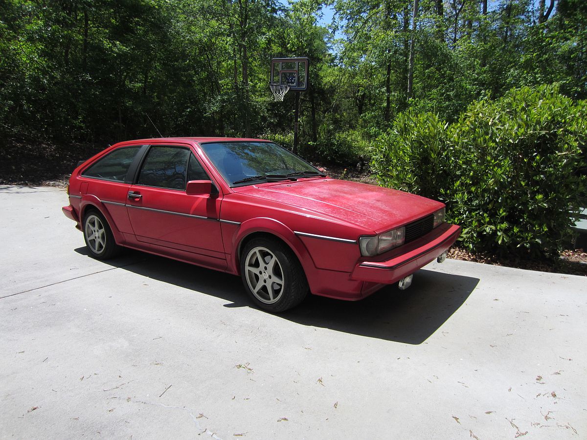
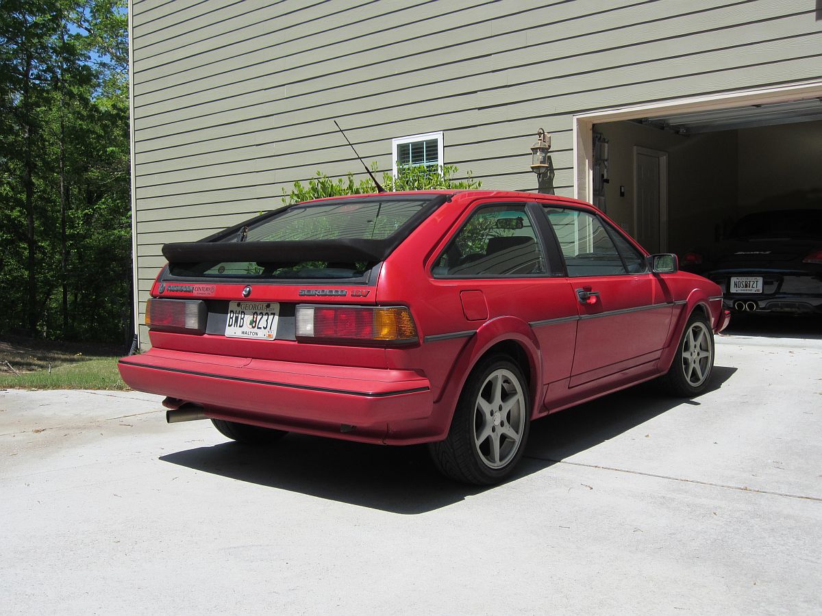
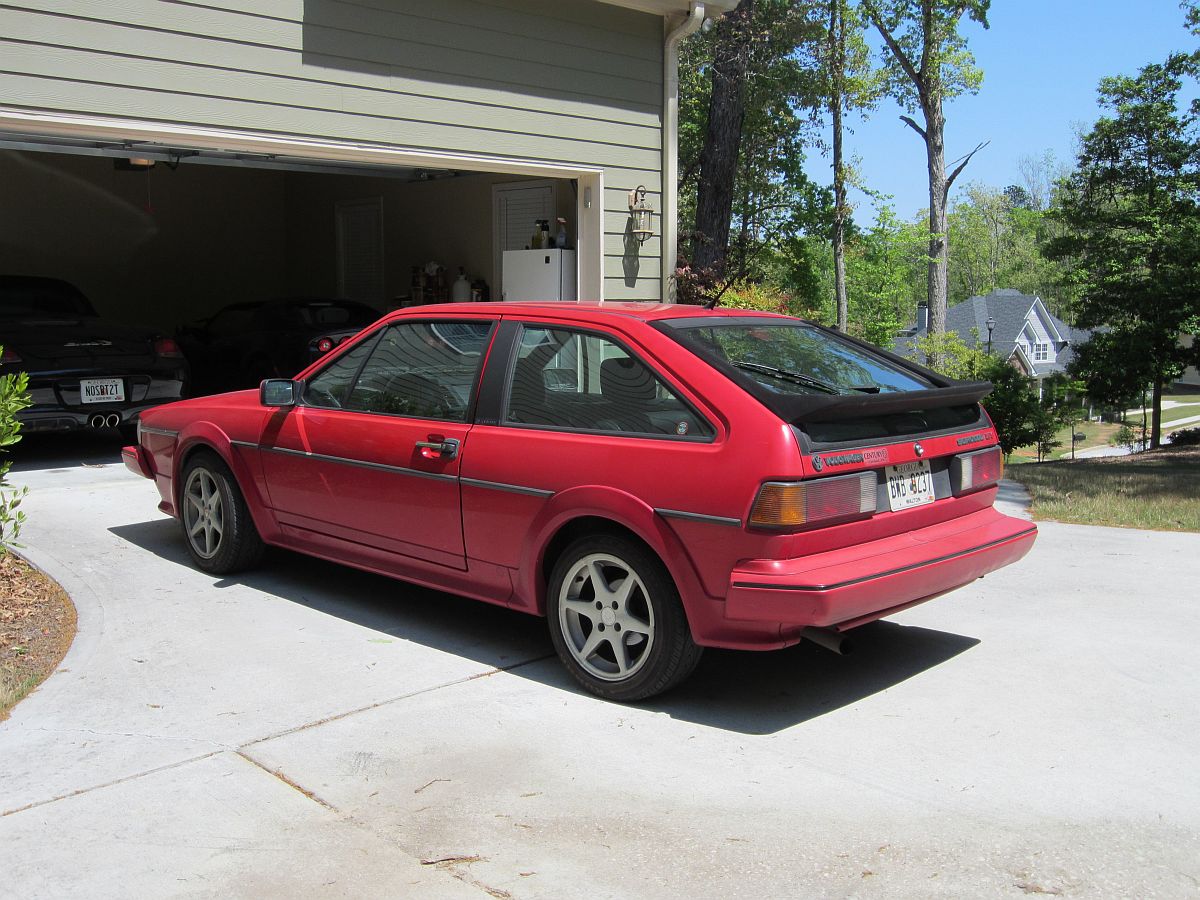
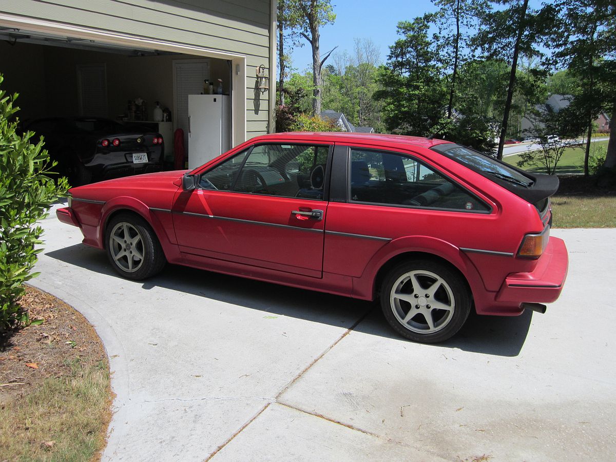
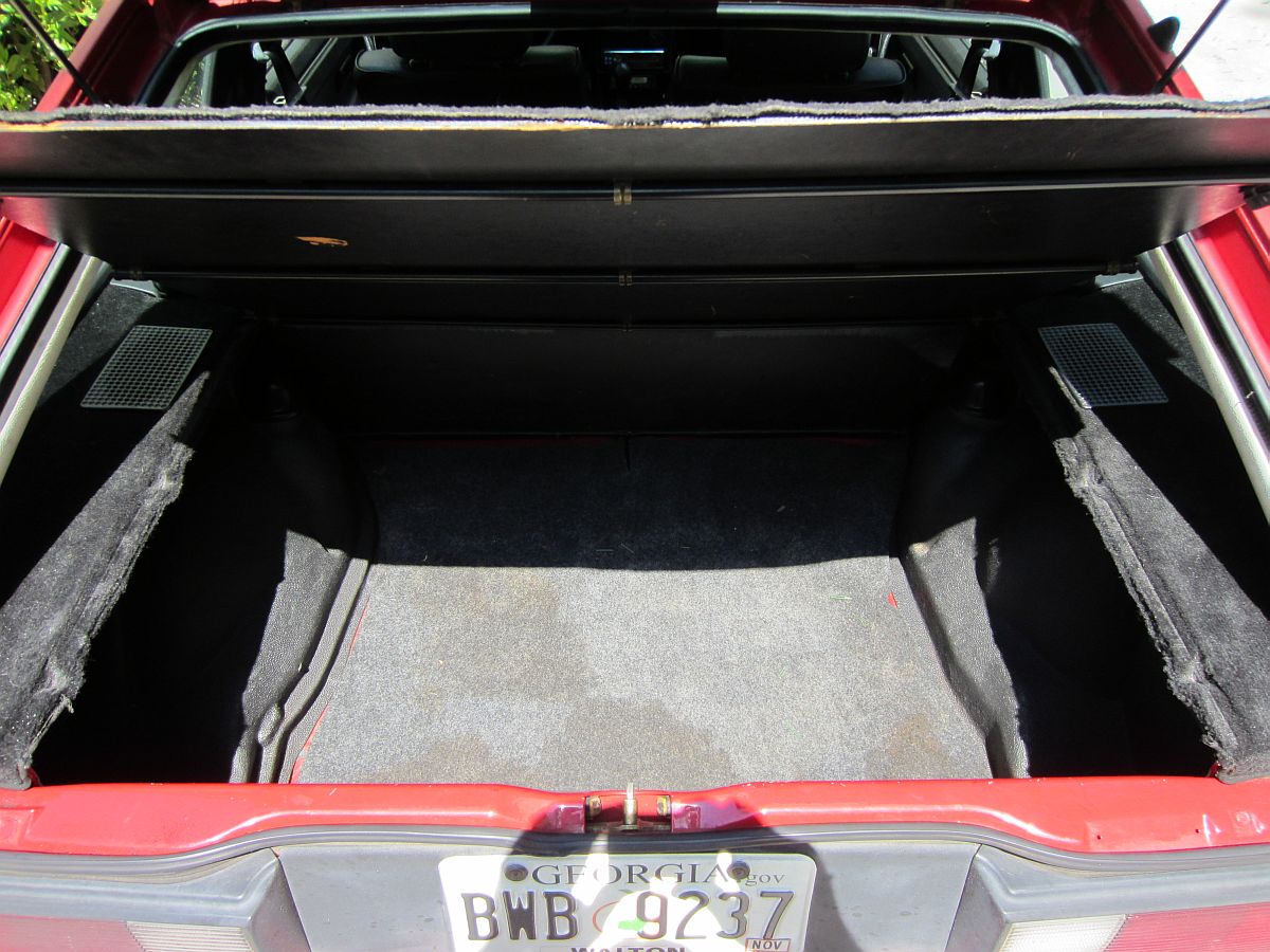
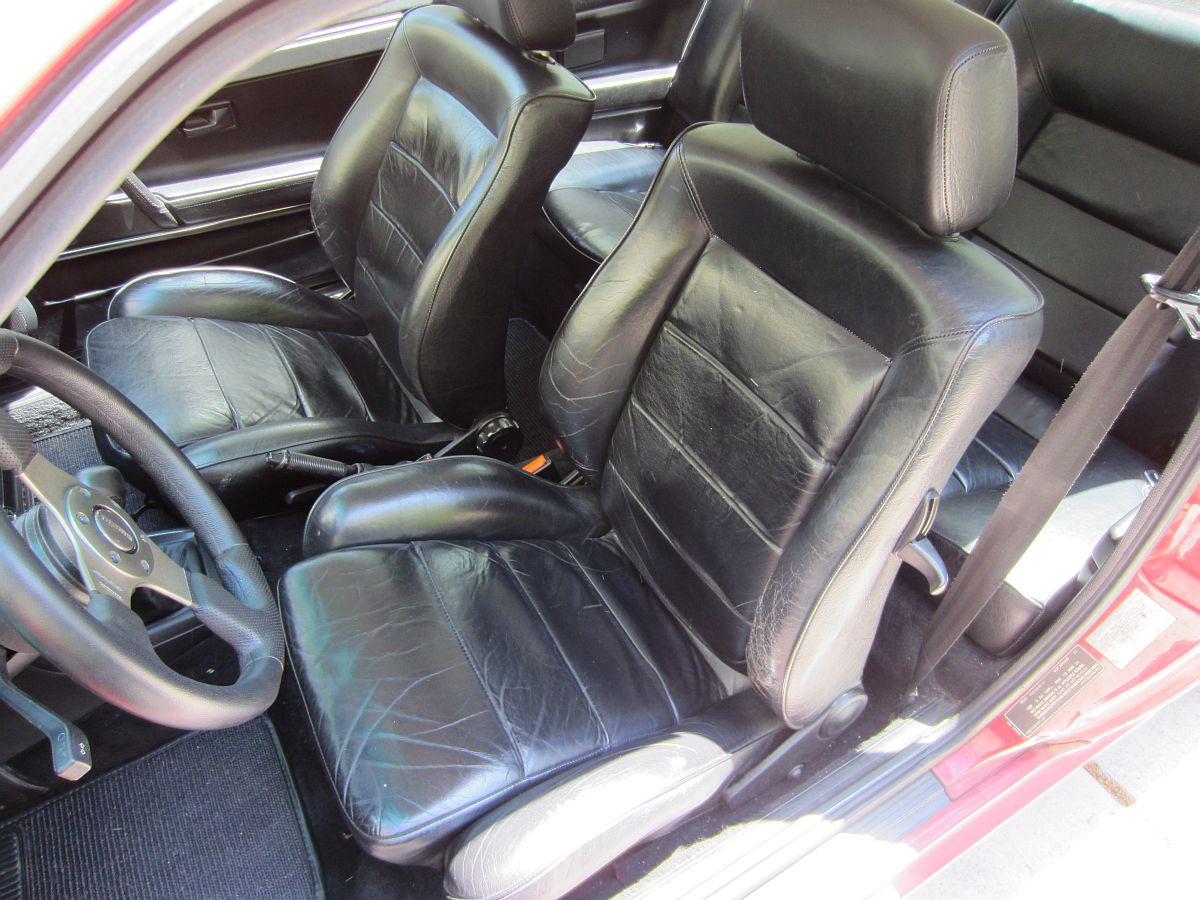
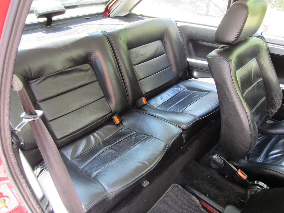
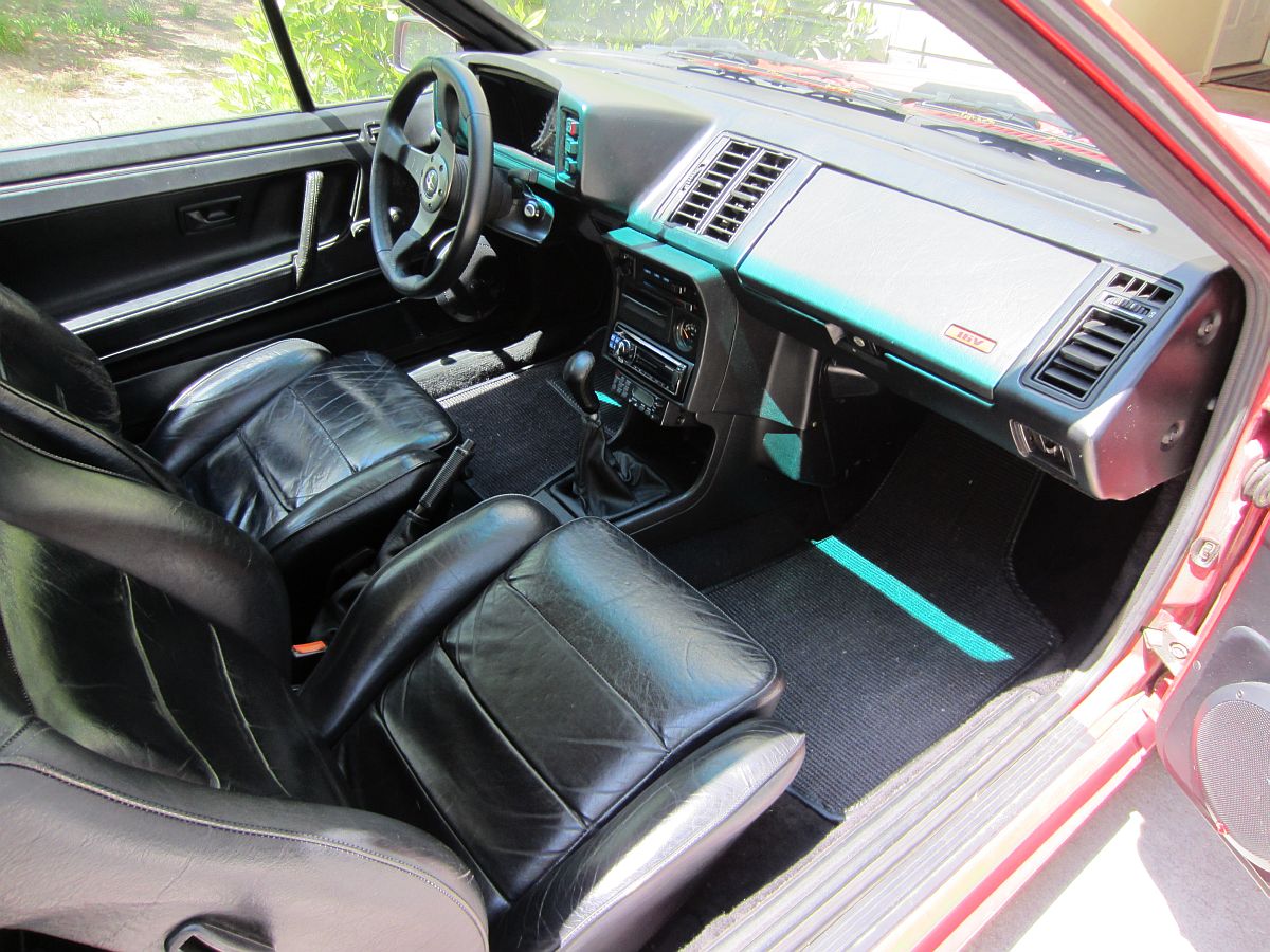
FOR SALE PICS (04/14/2012)
Scirocco Articles/Reviews:
Scirocco Buyers Guide
- from European Car 2005
1987 Scirocco 16v Road Test
- from Road & Track 1987
1988 Scirocco 16v Road Test
- from Road & Track 1988
Upshift, Collectible Classic: 1986.5-1988 Volkswagen Scirocco 16v
- from Automobile 2010
VW Scirocco Video:
*High Speed Connection Recommended*
Scirocco DIY Guides/Information:
Drivers Found:Scirocco- Information and Tech Tips/DIYs
Bad Habit Rabbit- Some DIYs for the Rabbit applicable to the Scirocco
BrokeVW.com- VW 020 Transmission Information and DIYs
A2 Resource-The Brochure Rack: Scirocco 16V Brochures and Ads
Removing SciroccoII Mirrors AND Assembly/Cleaning of Power Window Switch by VW Vortex's ginster86roc
Starter Bushing Replacement from VinceWaldon.com
Front Wheel Bearing Remove/Replace DIY from NorCalGTICup.com
Wheel Paint and Light Scratch Repair by AudiWorld.com's NASAracer
Scirocco Documents/Files/Links:
Online VW Parts Catalog (ETKA)
1987 Scirocco 16v Service Training
1986 Scirocco 16v Ad - "Powerful Argument"
1987 Scirocco 16v Ad - "Owner or Follower"
Car and Driver March 1983: Callaway Turbo Scirocco (courtesy of VW Vortex's 83Caddy16v)
Scirocco Forums:

Original Window Sticker HERE. 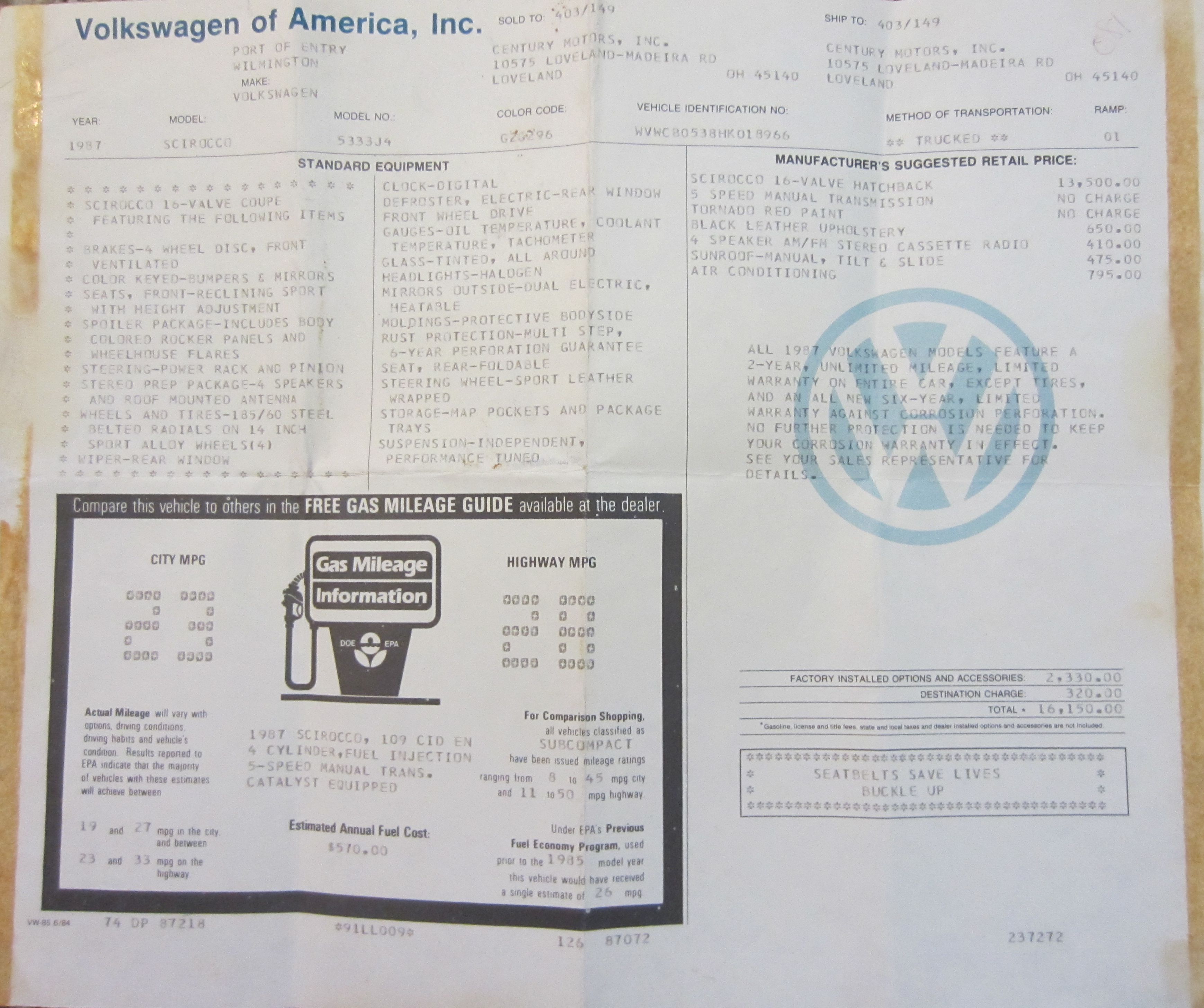


 ).
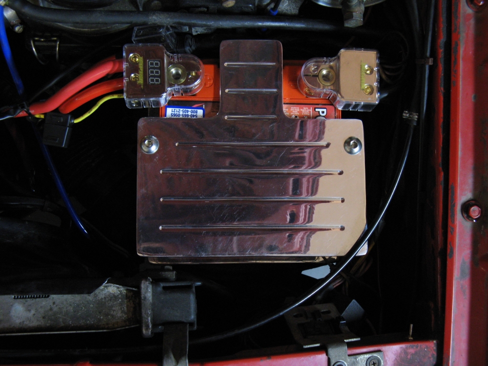
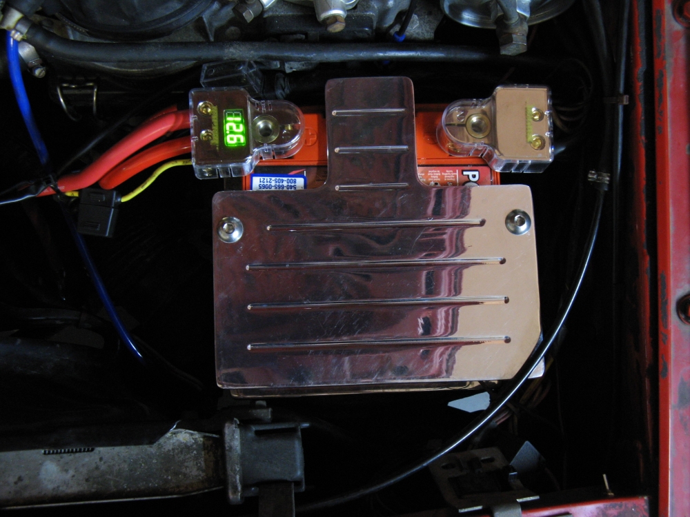
Next the EGR hose was replaced, the intake hose was repaired with E6000 adhesive, vacuum
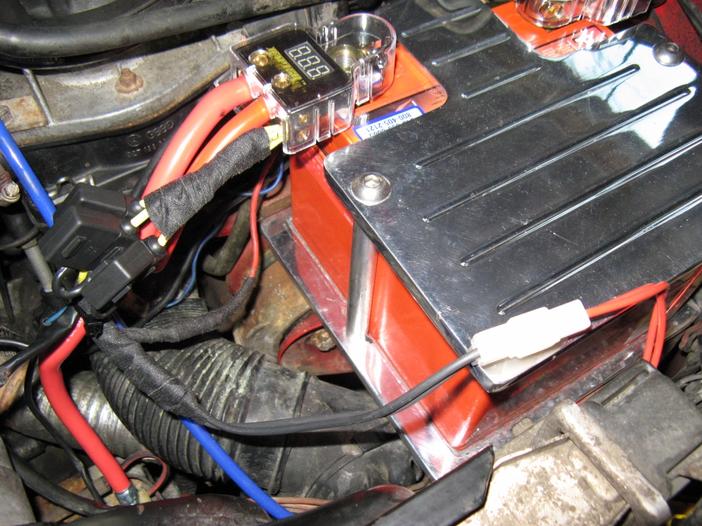
lines were all replaced, and the battery was mounted with new wires/terminals. The OE muffler also gave up the ghost so the SuperTrapp in the parts pile was
installed as a temporary solution. An Odyssey mount and PC925 battery were installed with new power/ground wires and terminals, the + terminal voltage display
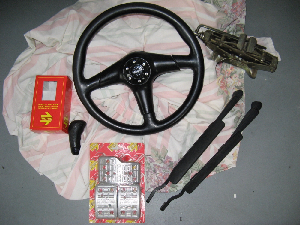
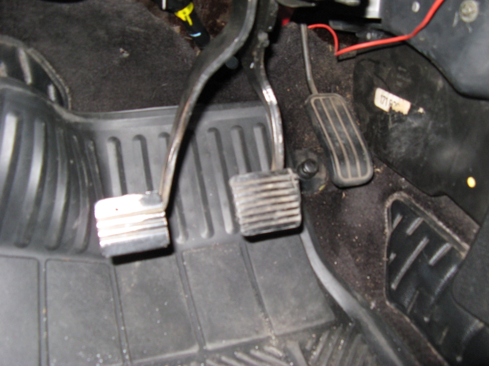
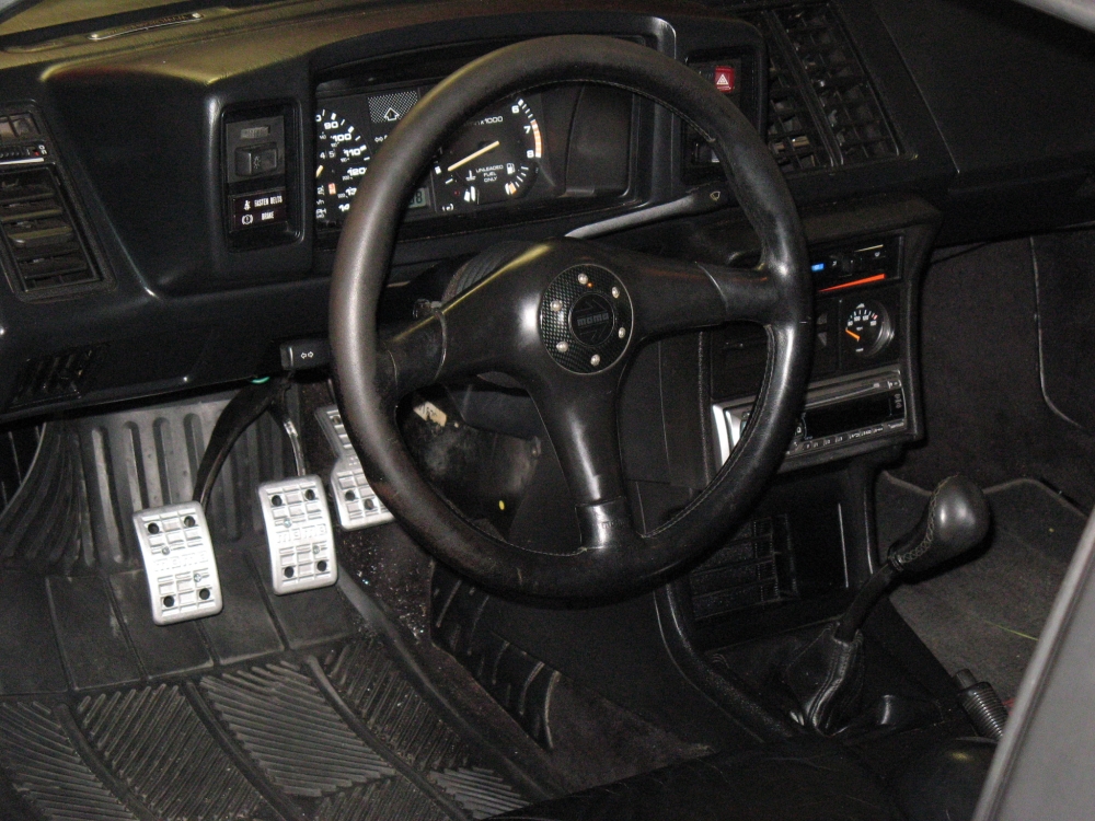
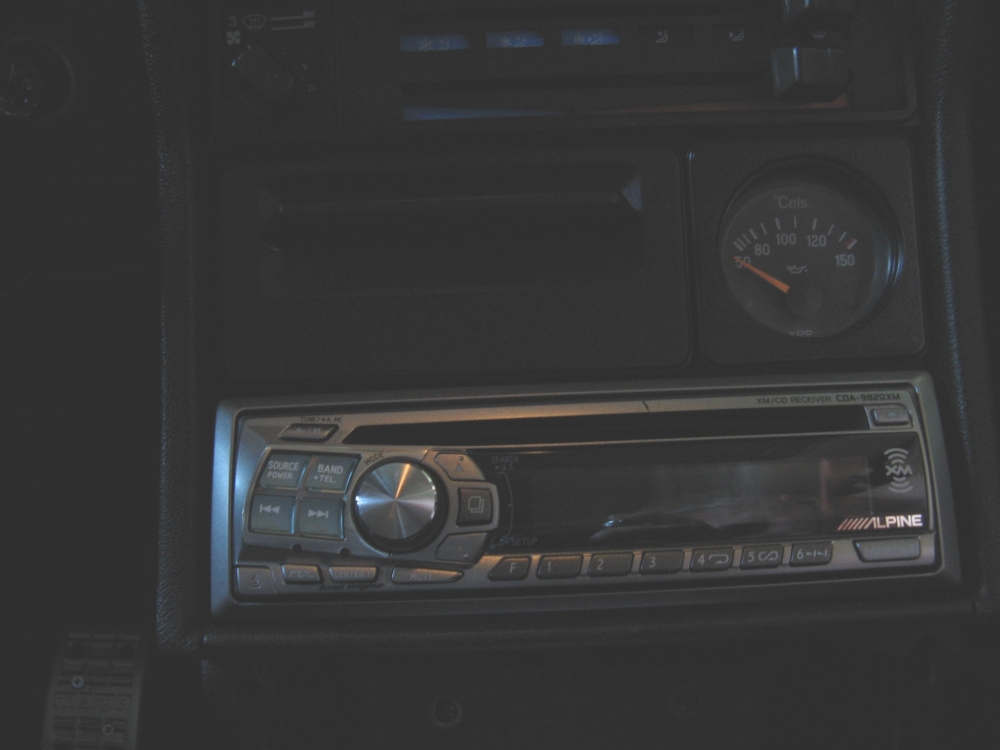
was wired to a switch (visible at lower right in pics). The fusible links had been removed from the fusebox power wires so they were fused (no fires needed). I found wiper arms and a jack from my old GTi,
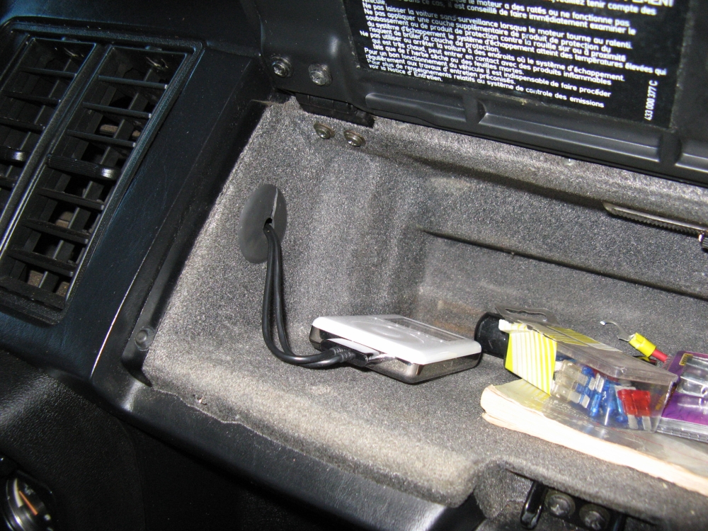
and Momo steering wheel/pedals/shift knob from past projects. I had an Alpine CDA-9820XM head unit from a past project that I installed along with
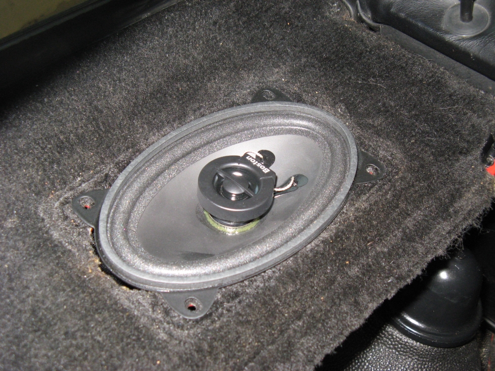
the Alpine KCA-420I for iPod control- iPod located in glovebox. New european-sized
Boston Acoustics CX7e 4"x6" speakers were
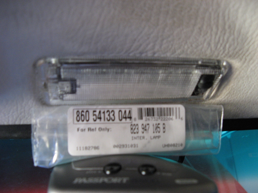
installed at all four corners, the rear grille speaker cloth had disintegrated and was replaced. Domelight above mirror was replaced with OE Hella part:
).
Next the EGR hose was replaced, the intake hose was repaired with E6000 adhesive, vacuum
lines were all replaced, and the battery was mounted with new wires/terminals. The OE muffler also gave up the ghost so the SuperTrapp in the parts pile was
installed as a temporary solution. An Odyssey mount and PC925 battery were installed with new power/ground wires and terminals, the + terminal voltage display
was wired to a switch (visible at lower right in pics). The fusible links had been removed from the fusebox power wires so they were fused (no fires needed). I found wiper arms and a jack from my old GTi,
and Momo steering wheel/pedals/shift knob from past projects. I had an Alpine CDA-9820XM head unit from a past project that I installed along with
the Alpine KCA-420I for iPod control- iPod located in glovebox. New european-sized
Boston Acoustics CX7e 4"x6" speakers were
installed at all four corners, the rear grille speaker cloth had disintegrated and was replaced. Domelight above mirror was replaced with OE Hella part: 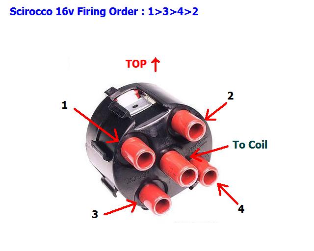


 ).
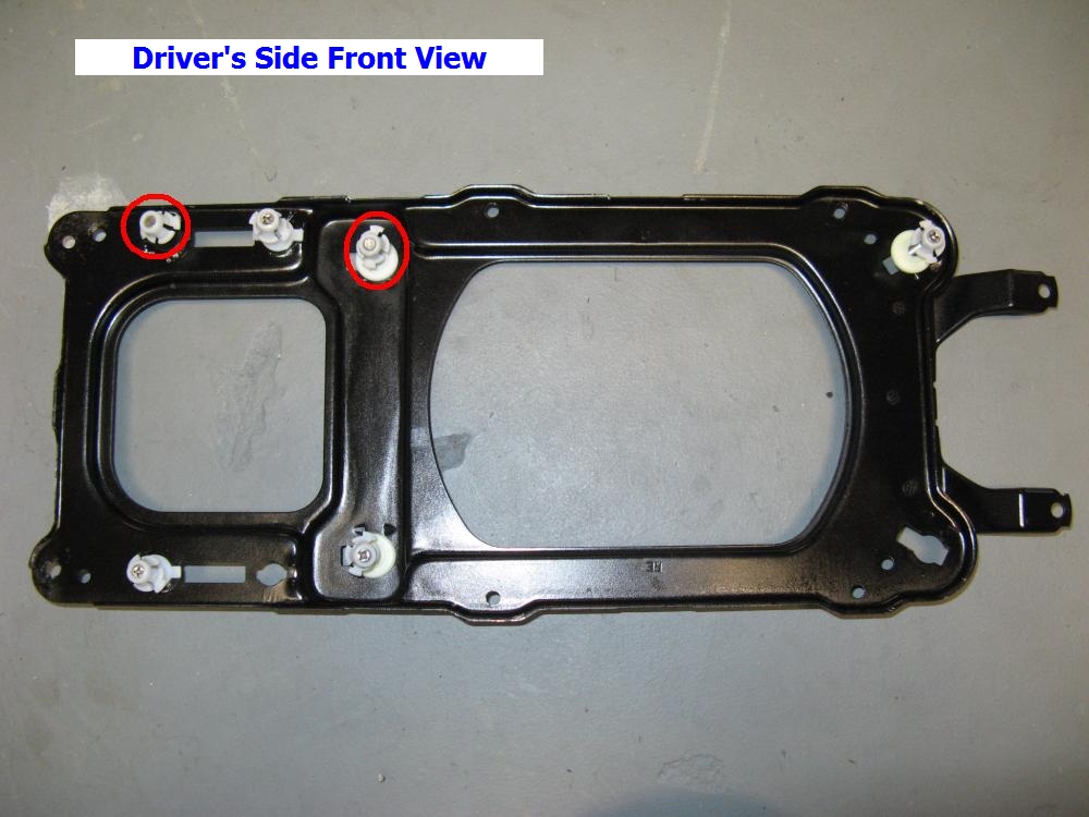
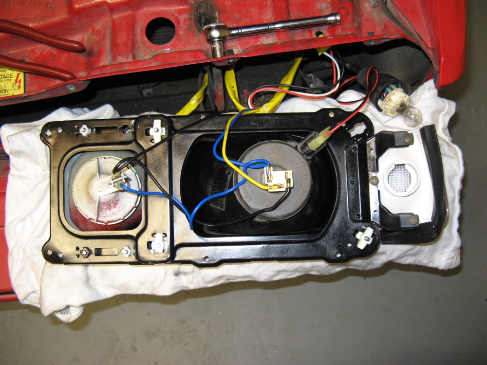
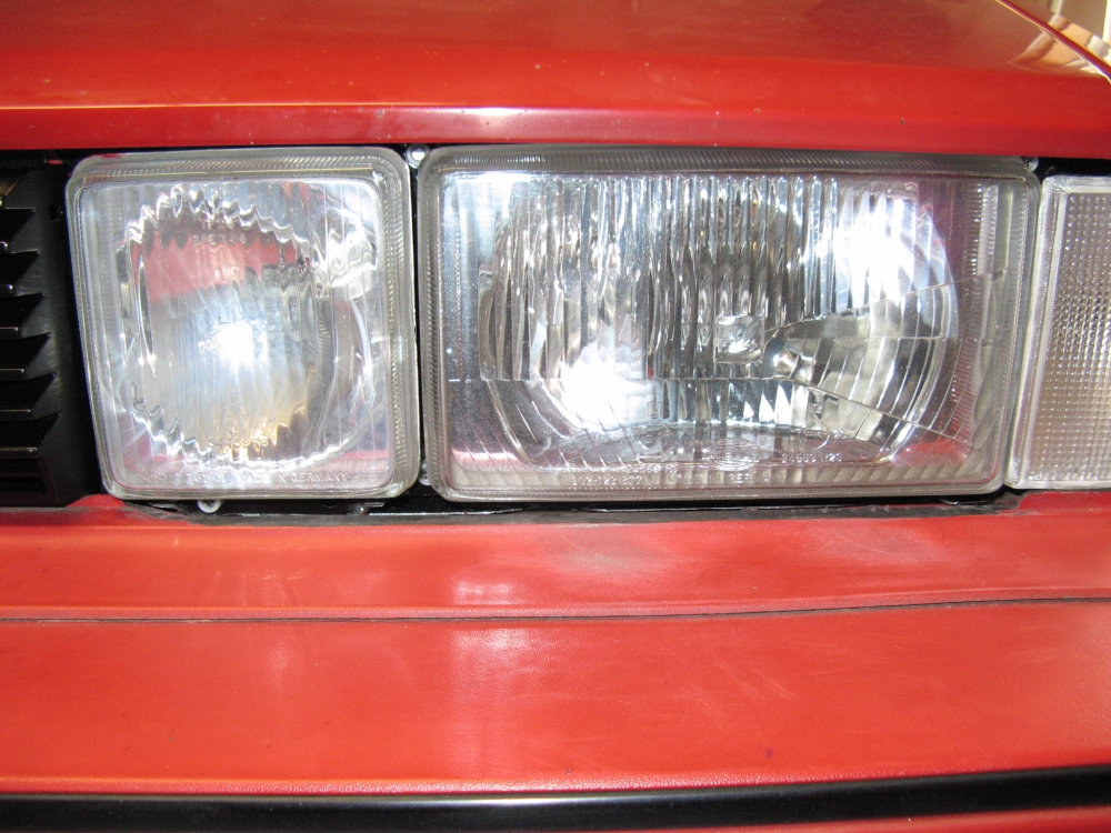
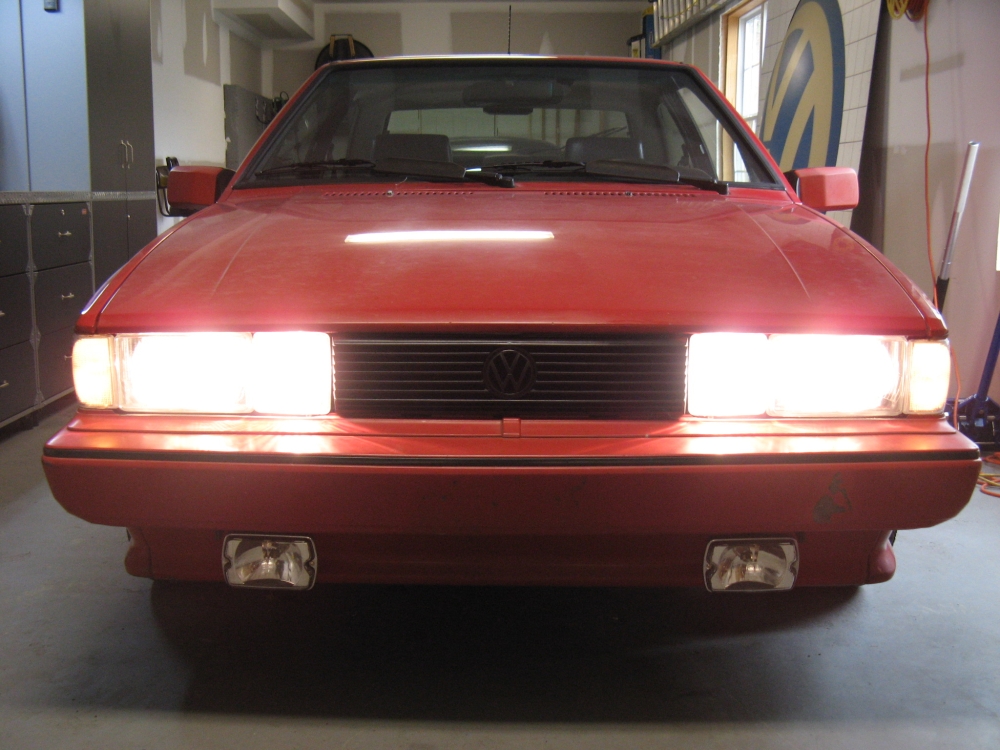
I went with Sylvania Silverstar H3 and H4 bulbs. The adjuster tabs were missing
and sourced from Parts4VWs. Some slight changes were made to the
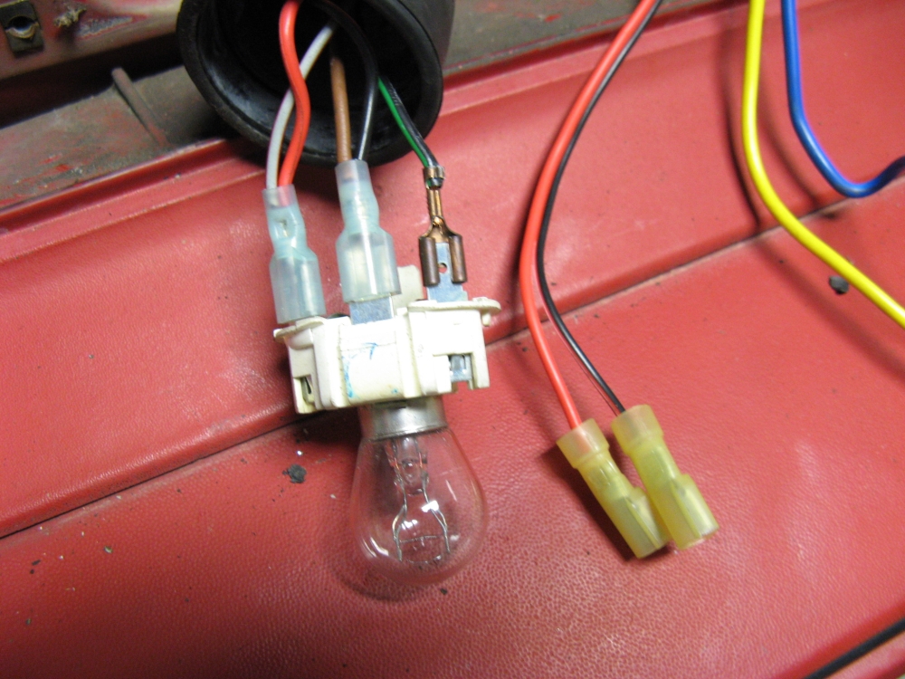
wiring harness- the "city" light bulb in the main reflector was tapped into the existing parking light circuit, the high beam H4 connector was cut off and
replaced with spade connectors to work with the H3 bulbs, and the input plug pins were reorganized to work with the factory VW plug. The headlight backing plates and headlights
were masked and painted black to cover the previous overspray, the adjusters were installed using needle nose pliers to twist them into locked position (be CAREFUL, these adjusters are EASY to break)
- note the circled mounting pins are the ones that offer no adjustment. I also applied some Lamin-X 20 mil protective film to all four glass lenses prior to installation.
).
I went with Sylvania Silverstar H3 and H4 bulbs. The adjuster tabs were missing
and sourced from Parts4VWs. Some slight changes were made to the
wiring harness- the "city" light bulb in the main reflector was tapped into the existing parking light circuit, the high beam H4 connector was cut off and
replaced with spade connectors to work with the H3 bulbs, and the input plug pins were reorganized to work with the factory VW plug. The headlight backing plates and headlights
were masked and painted black to cover the previous overspray, the adjusters were installed using needle nose pliers to twist them into locked position (be CAREFUL, these adjusters are EASY to break)
- note the circled mounting pins are the ones that offer no adjustment. I also applied some Lamin-X 20 mil protective film to all four glass lenses prior to installation.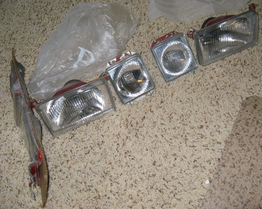


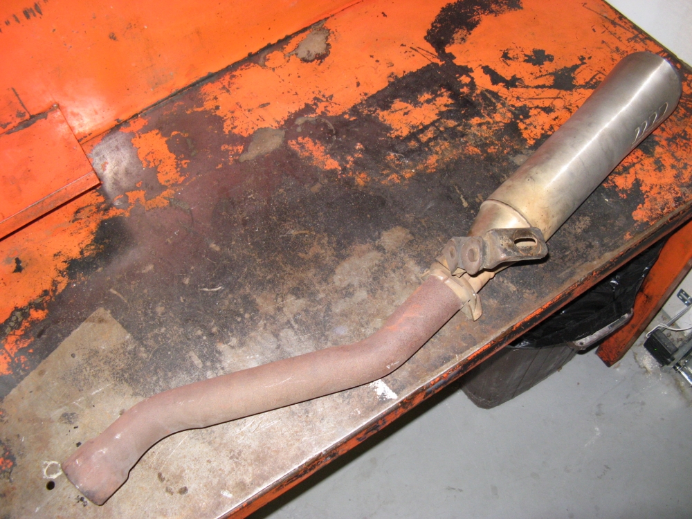
Comparing the OE exhaust manifold/downpipe to the header, it is easy to see how much weight will be saved and how it is quite possible for the exhaust to flow better.
Header pictured with NEW OE O2 sensor.


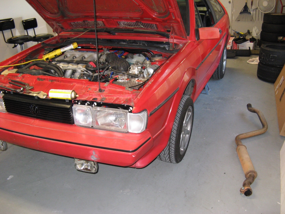


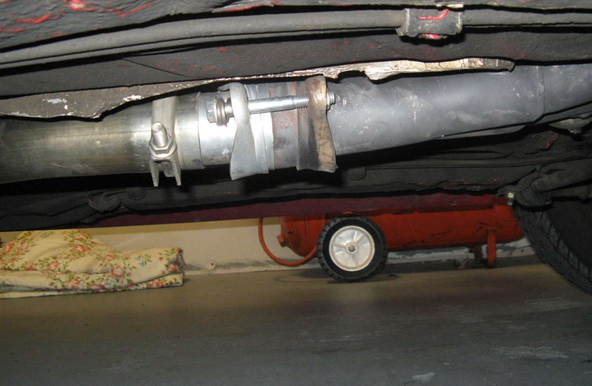
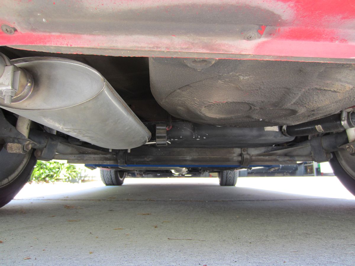
This was installed at the same time the header above was installed so the exhaust on the car had already been removed.
I started at the front and worked my way back, loosely installing clamps until everything was together and some slight adjustments were made, THEN tightening the
clamps down. This exhaust sounds great and will probably outlast the car  ......


 Installation instructions HERE.
The car handles much better now, less body roll and turn in is much better, this bar has dialed out most of the understeer.


 . The USRT Heim joints and other shifter bushings should periodically be dosed with lithium grease:

 .
.


 .
.


 .....I have learned this lesson the hard way in the past. Plug physically functions much better now:
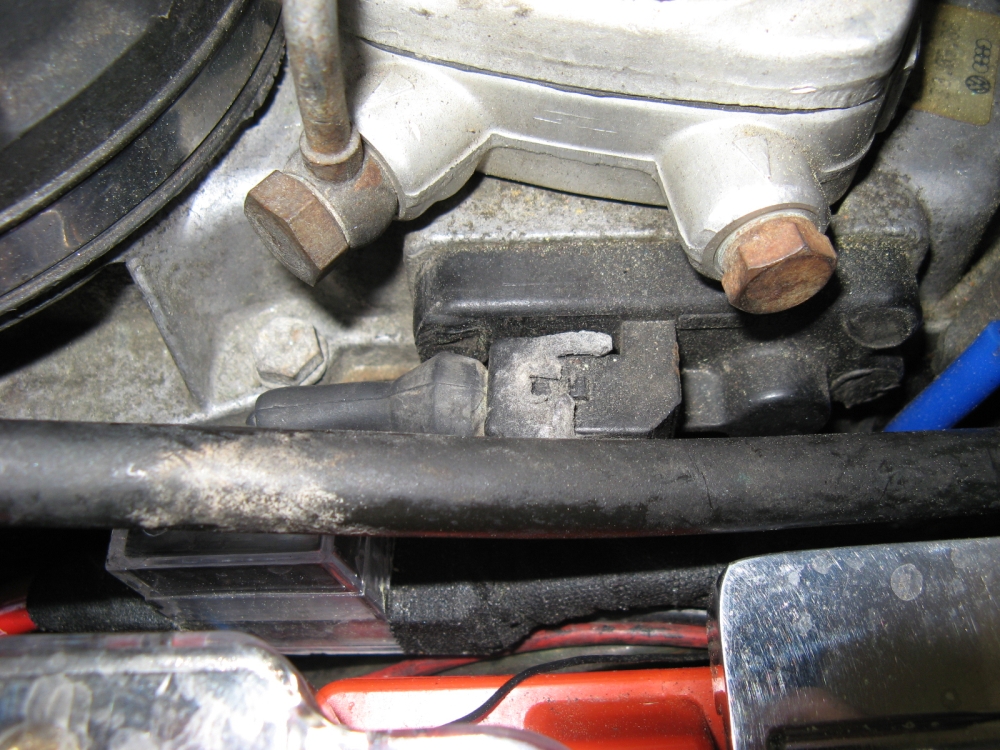


This is available from Mike via this
VW Vortex post, for best (fastest)
results call him (407-447-5363) , don't rely on IMs or email (mike@forgemotorsport.com):


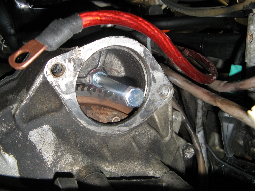
The old starter was removed by first removing the power steering hose support on bottom, and then the lower bolt/nut mounting the starter to the front engine
mount- the top bolt was removed last. The top and bottom bolts were removed with a ratchet, extension, and hex socket- the bottom nut requires a wrench, the top
"nut" is captive (welded to and part of the front engine mount).
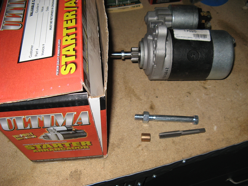
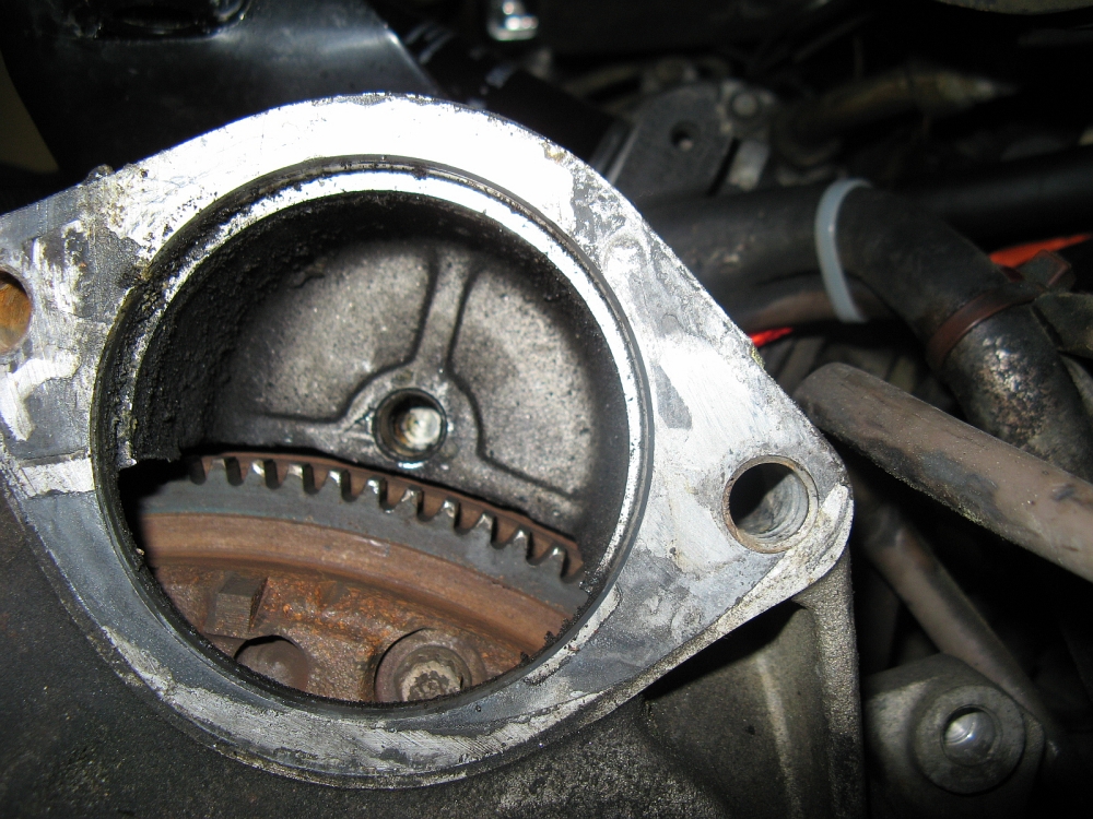
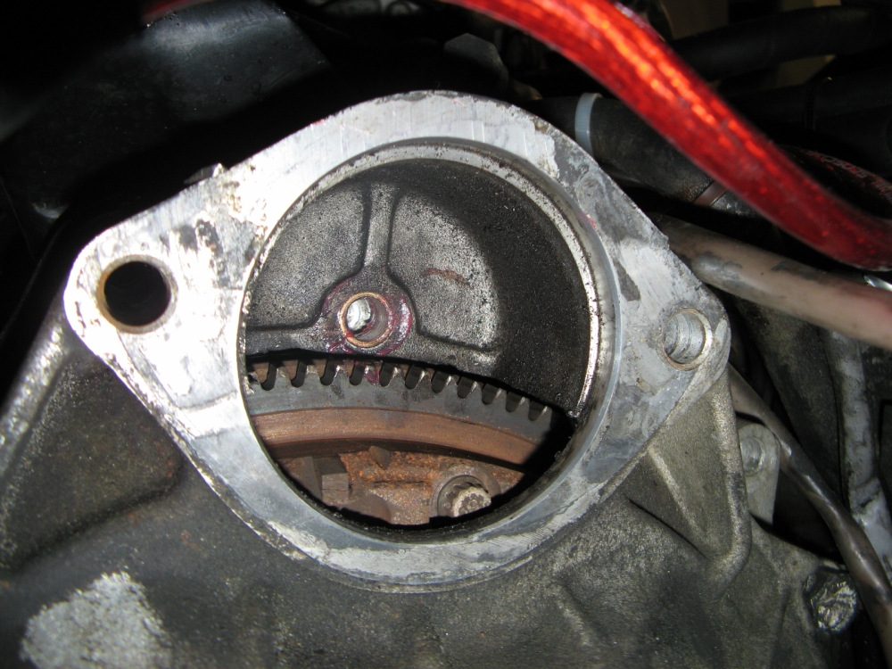
Part of the warranty conditions were that the supplied starter bushing needed to be installed in the transmission housing. This required an 11mm tap to
remove the old bushing and a tool made with a 7/16" nut and bolt to drive the new bushing into place as per
Vince Waldon's website DIY. One additional step
I took was to lightly file a chamfered edge on the new bushing on the entry side so that it would center in the hole to be pushed into place with the help
of a rubber mallet and a few light taps. Some Mobil1 grease was used to coat the inside and outside of the bushing prior to installation.
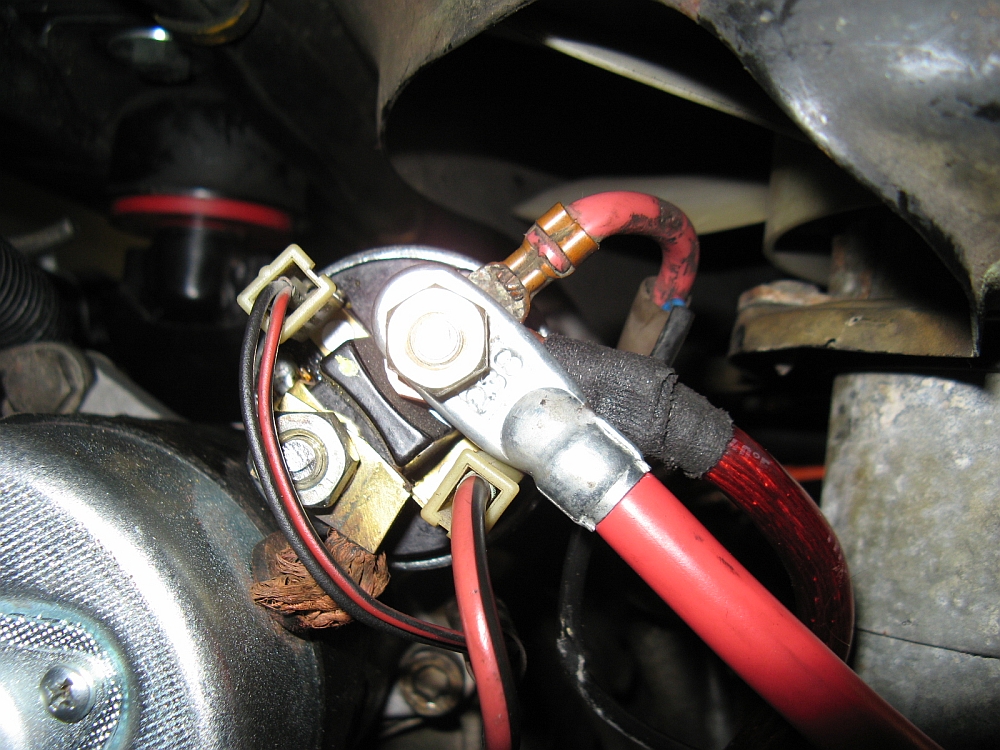
Installation is reverse of removal . I found removing and installing the starter was easiest from below with the car on ramps.
The new starter had a small spade adapter that I removed since my connectors were the fullsize spade, the electrical connections were hooked up the same as
they had been with the OE starter. Car starts fine now so the starter was the issue:


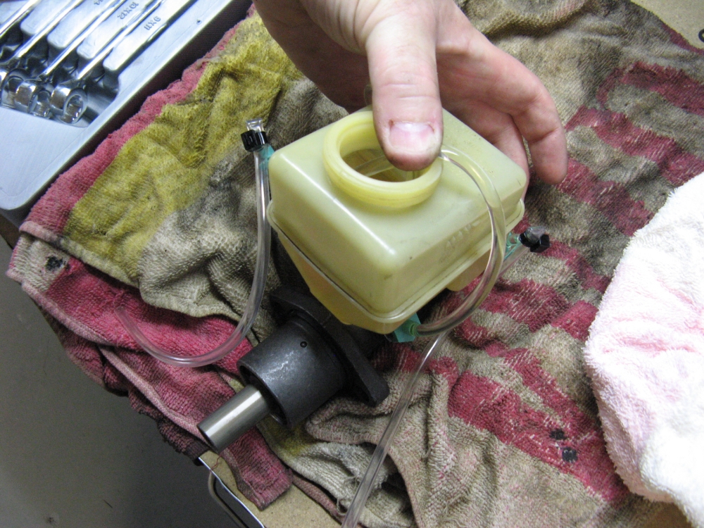
The new master cylinder will need to be bench bled using the tubing and fittings provided. The brake proportioning valves need to be installed on the master
cylinder during the bench bleed process, since only one of mine was directly attached to the master cylinder and the other was downstream in the middle of
a brake line, I just went with the one that was attached to the master cylinder- I felt that the regular bleeding process would work fine for catching the other one,
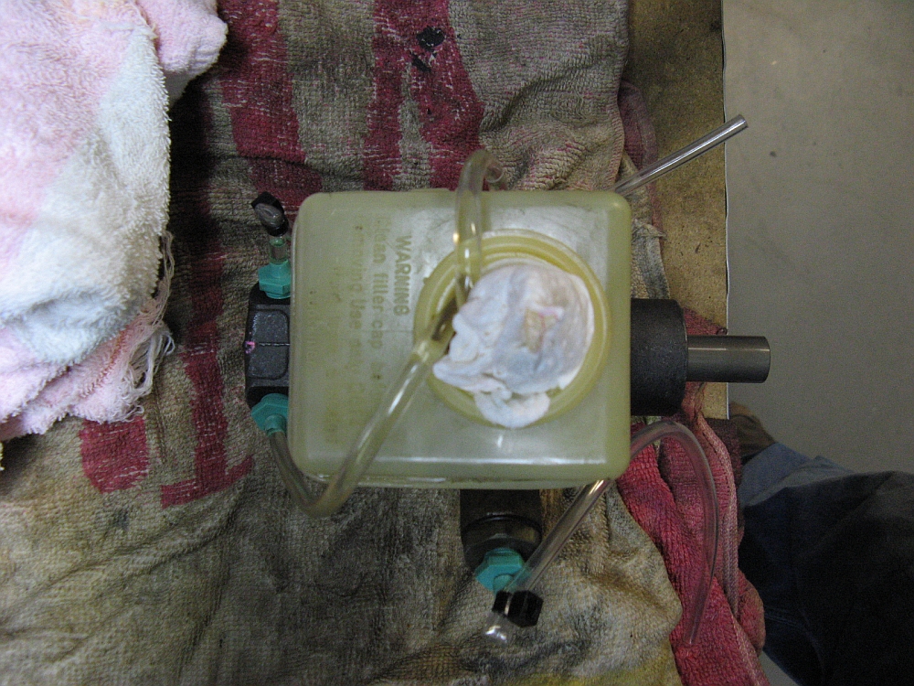
YMMV. I rinsed out the master cylinder with some clean brake fluid to get the sediment out of there and then followed the instructions by lubing the two reservoir
seals/grommets with brake fluid and pushing the reservoir down and into the new master cylinder, you should be able to feel when it is properly seated. The two
master cylinder lines WITHOUT proportioning valves are looped into the reservoir that is now filled with clean fluid, the other two are capped off. The bleeding
process involves pushing the master cylinder piston in/releasing until no more air bubbles are seen in the lines going back into the reservoir. The new master cylinder is then reinstalled
after removing the bench bleed fitting and lines, installation is reverse of removal. I used brake cleaner without prejudice to remove any brake fluid from the engine
bay and then moved to bleeding the brakes with my Motive Black Label pressure bleeder, RR>LR>FR>FL.
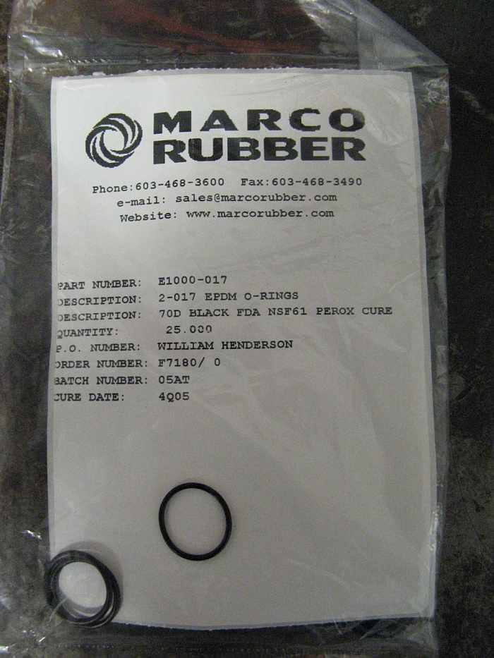
I searched the internet for a few hours to figure out what material the o-rings needed to be to play nice with brake fluid and where I could source them.
I found that they needed to be EPDM (ethylene propylene diene monomer) type o-rings and found a place called Marco Rubber that
sold a gazillion different types of o-rings with various diameters and sizes, and fortunately
had what I thought would be close to a replacement for my proportioning valve, P/N E1000-017. I actually ordered 2 different sizes to minimize downtime in the event
that one size did not work.
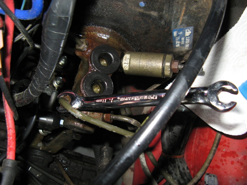
The proportioning valve was taken apart by clamping the bottom wrench flats in a vice and using a wrench to remove the top. Sorry I didn't take pics,
but the parts should be placed in a logical order if removed so that you can reassemble the valve. I cleaned up all the pieces and reassembled the valve using my new o-ring
and it worked-success at last and no more leak. The only thing that ever goes wrong with these proportioning valves is probably the rubber o-ring, and a
bag of 25 for ~$10 is a bargain compared to the price of a new valve (who wants a used valve- you already have one of those).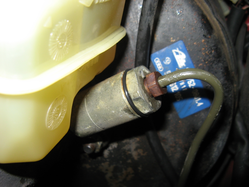

The DIY that worked for me was the one here (http://www.garageprosoftware.com/scirocco/tech_odometer.htm) but there are a few more
on the Vortex Scirocco FAQ HERE and another HERE.
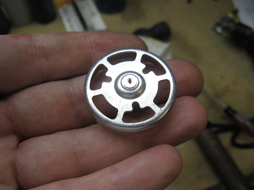
Not much for me to add....but be prepared to need a spare cluster for parts, these old parts have a tendency to resist repair. I found that by pulling the speedo
needle off carefully, the speedo shaft snapped, maybe defective? Anyway, I purchased a spare from a Vortex member and canibalized the speedo drive parts that I needed and
used needle nose pliers to rough up the gear shaft at the metal gear position- I had to use a rubber mallet to beat the shaft back in the gear set so hopefully it won't slip again
any time soon. Not so surprising, my mileage has gotten better :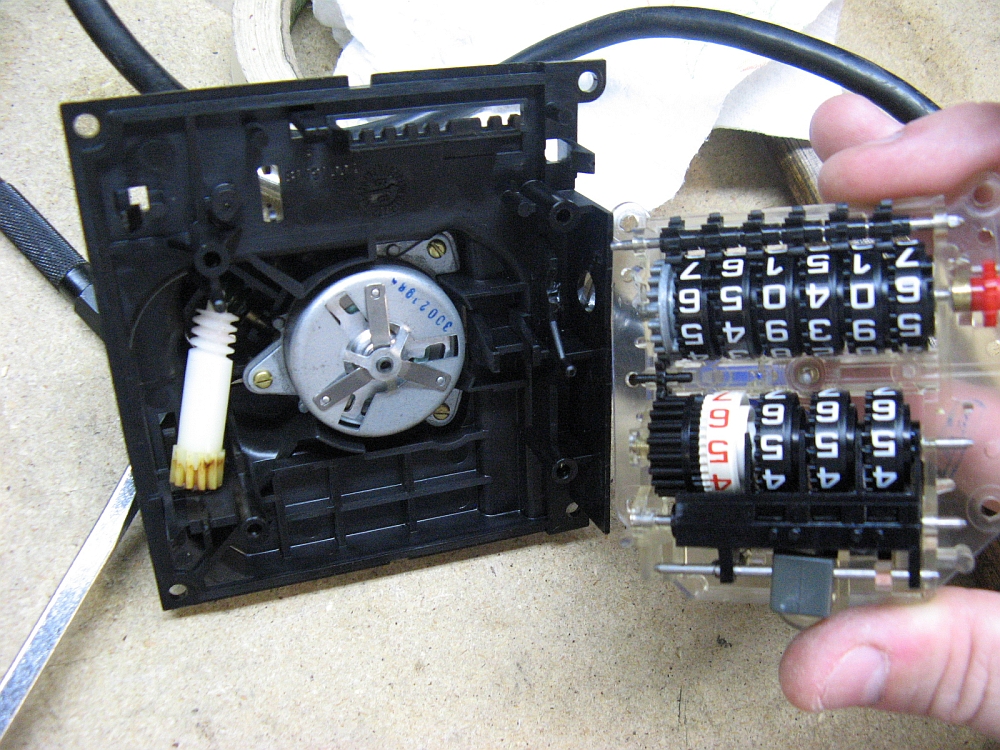

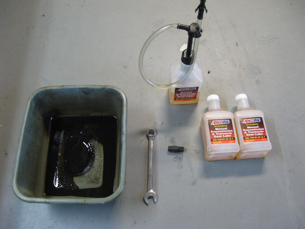
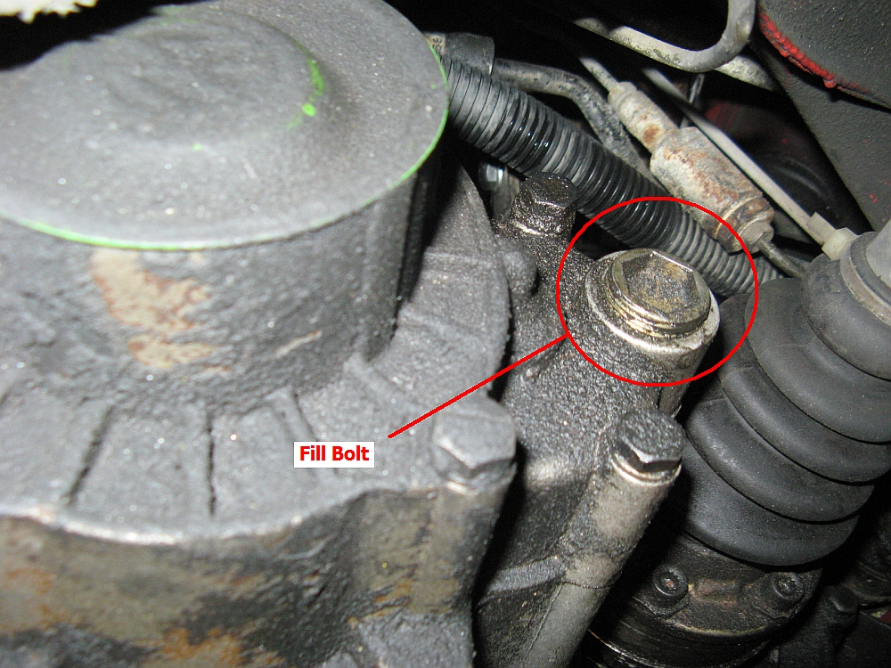
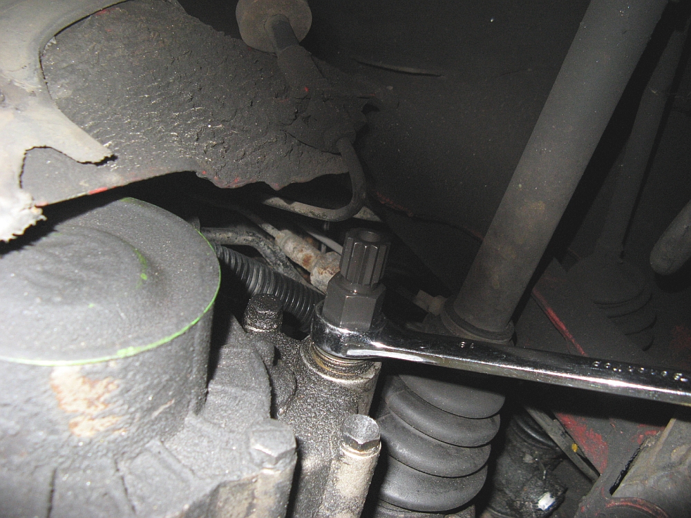
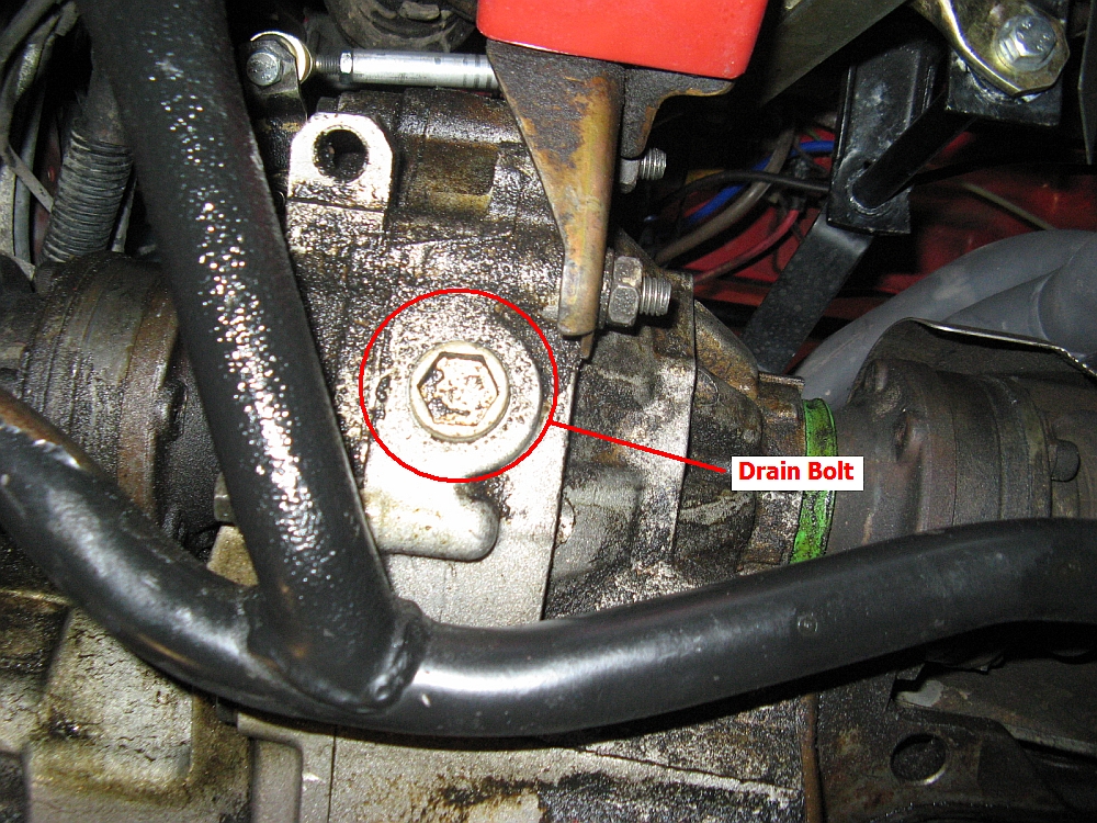
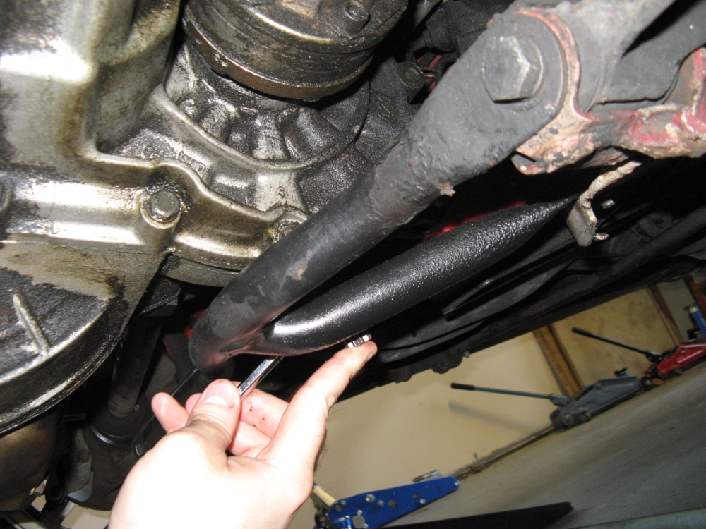
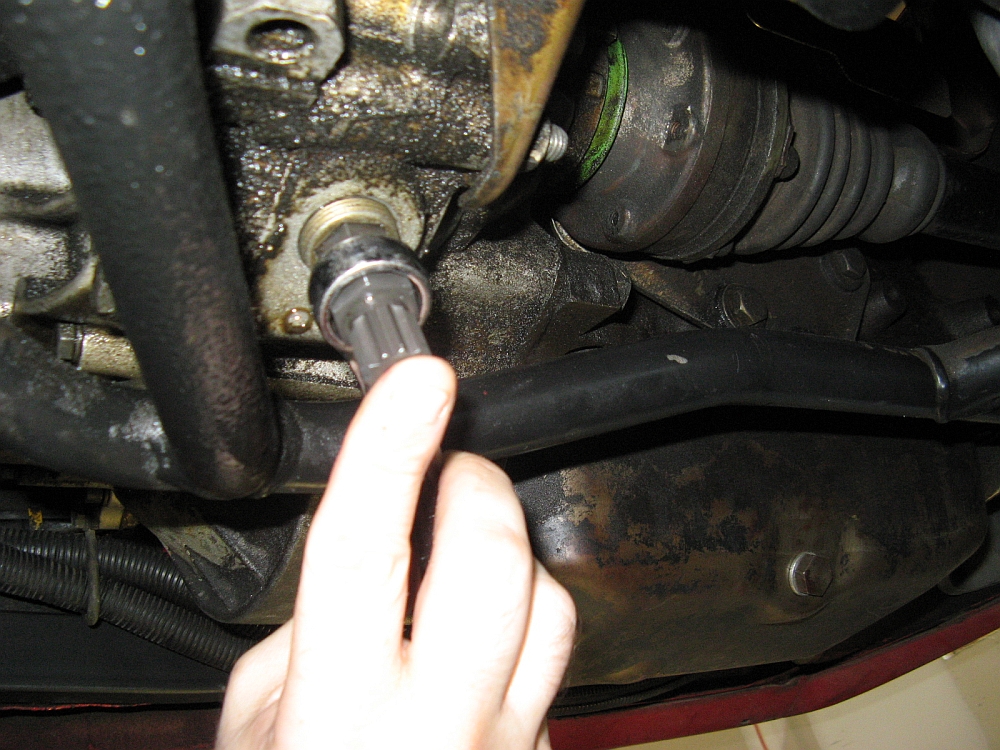
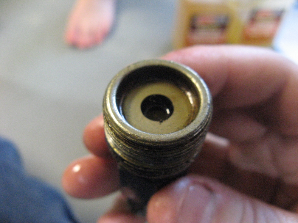
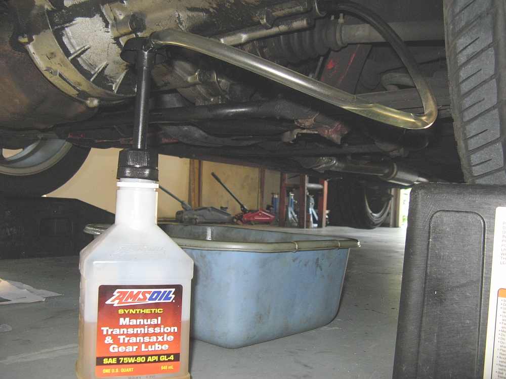
Simple change- Remove fill bolt, remove drain bolt, drain old fluid into pan,
clean/replace drain bolt, jack car on drivers side to facilitate 2.1 quart fill in old style fill hole, clean/replace fill bolt.
I used Amsoil MTF 75w90 GL4 for this change since I have had great results with it in the past.
Great primer on the O2O transmission used in the Scirocco and transmission fluid change HERE.
I found the driver side plastic piece that is the armrest and housing for the door latch was barely bonded to the door so a quick detour was needed to reglue this,
I used E6000 and taped it in place and let dry. If I keep the car I feel sure I
will be redoing this in fiberglass, the plastic has become pretty brittle and cracks/breaks easily.
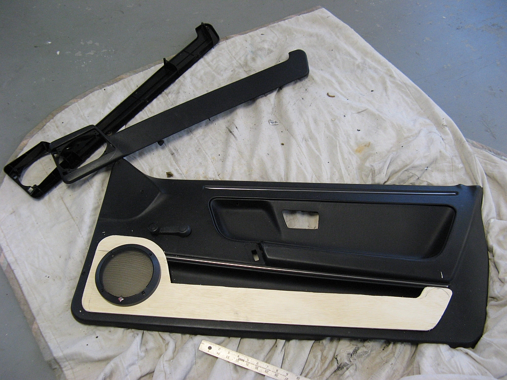
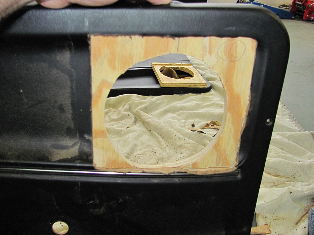
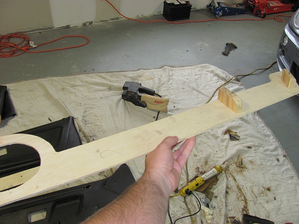
I really wasn't sure how I wanted to do the speaker door panel replacements at first, but after playing with a few different ideas decided on using thin plywood (1/8" thick)
for the face and use 3/4" plywood on the back to sandwich the door panel and clamp down when the speaker was screwed down through all 3 pieces for stability.
Another thing to consider was the window cranks, the design needed to clear those
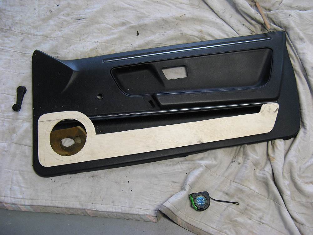
so that they would still be functional. The face pieces were cut first to cover the molded door pocket and
allow for a 6.5" speaker hole to be cut, two small pieces of wood were cut and shaped to hold the face on the door at the original door pocket screw points.
Next the door panels were cut (measure three times and cut once, door panels are harder to replace than wood). Finally,
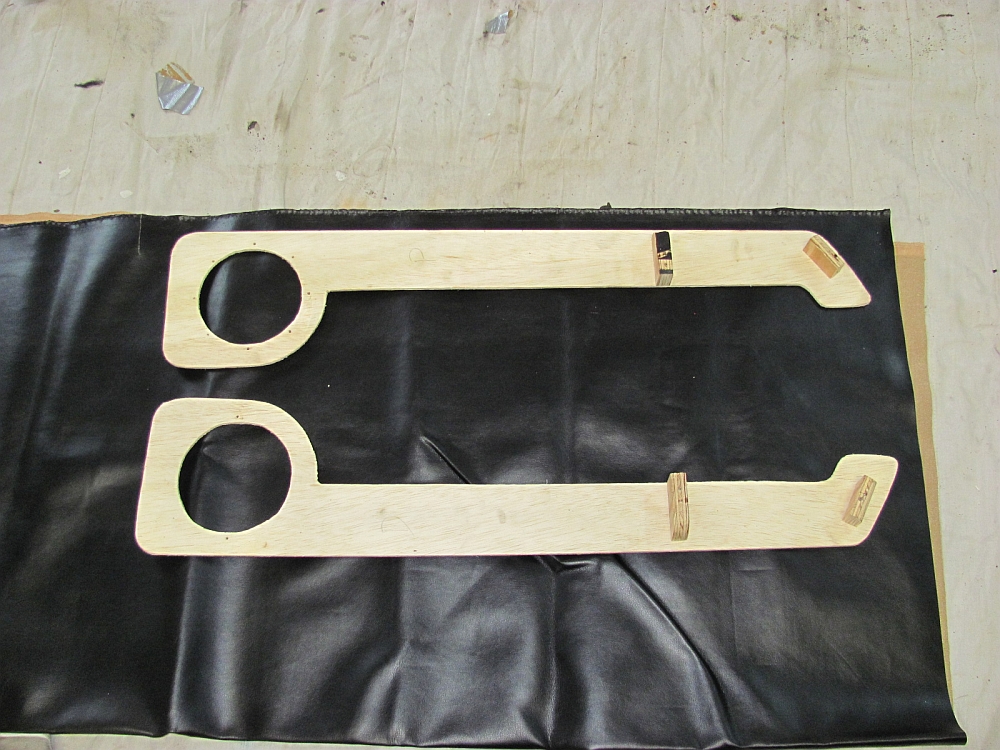
the rear pieces were cut and after alignment with the face pieces were glued into place with E6000
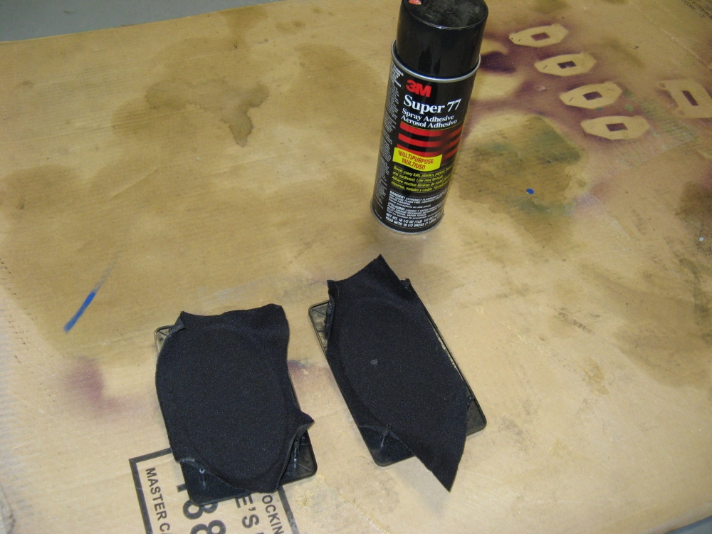
and allowed to dry overnight. The next day the face pieces were
covered in vinyl, I lucked out and hit a half price sale when sourcing vinyl at the fabric store. Good vinyl costs a bit more but is MUCH easier to work with,
3M Spray 77
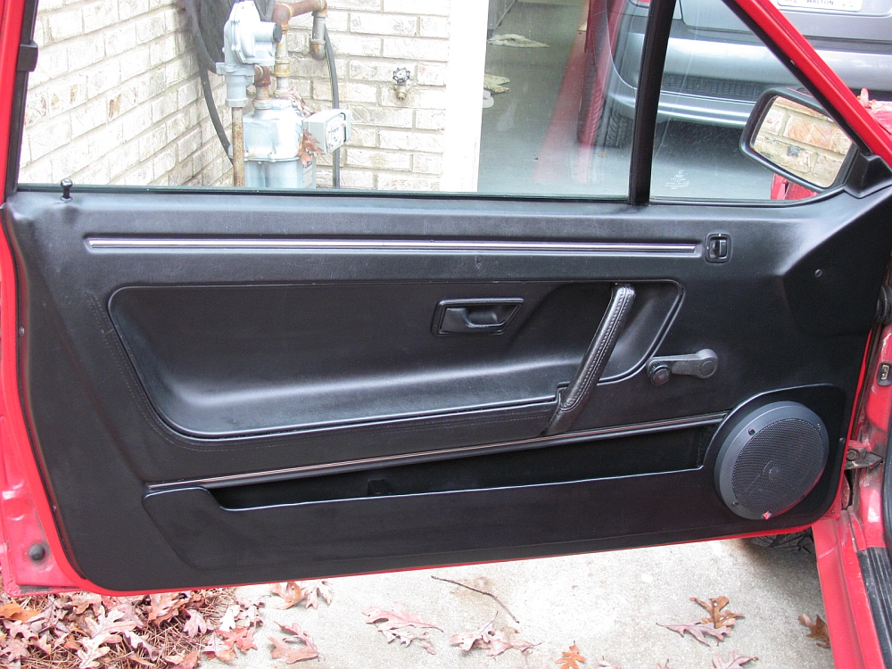
was used to bond the vinyl to the wood. The door panels were reassembled and reinstalled. The door needed a little persuasion that these speakers would fit,
a ball peen hammer was used to provide a little additional clearance on the bottom and front edges of the original speaker cavities.
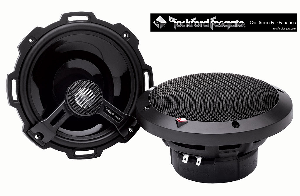
The sound is MUCH improved with the 6.5" speakers, I used Rockford Fosgate T1652
Power series speakers, the tweeters are angled up and the sound is perfect.
Owner's Manual for the speakers can be found HERE.


The approach I used was to remove the two Phillips head screws at the base and free it, then to remove the clip at the top and pop the strut off the upper mount- the old clips were wire clips and need to be rotated/unclipped from the strut before pulling down and out of the hole, the new style clips can be removed using a small standard screwdriver to pry off. Once the strut is removed, the lower retaining pin can be removed by first using a small standard screwdriver to remove the circlip and pushing the pin out- WD40 is helpful here to free an old somewhat rusty pin like mine. The new strut is positioned in place and the pin reinserted through the lower mount and strut and the circlip then reattached using pliers. Make sure the plastic base is aligned properly, insert/tighten down the two screws, and snap the strut top on to the ball joint. Done.
I found the struts felt OK when off but just didn't have enough strength left to support the hatch.


 Timbo's Tech Notes: A1 Engine Mounts
Timbo's Tech Notes: Cleaning the CIS Airflow Sensor by ATS
Timbo's Tech Notes: Setting the Air/Fuel Ratio
Timbo's Tech Notes: Replacing or Upgrading the Brake Master Cylinder
Timbo's Tech Notes: Relay DIN Standard Terminal Definitions
Timbo's Tech Notes: OXS/Oxygen Sensor Light Reset Procedure
Timbo's Tech Notes: Exhaust Studs
Timbo's Tech Notes: Foglight Relays
Timbo's Tech Notes: Installing Headlight Relays
Timbo's Tech Notes: Fuse Panel Quick Reference
Timbo's Tech Notes: Tail Lights- Removing Ridges and Polishing by VW Vortex's ginster86roc
Timbo's Tech Notes: Re-Keying Door Handle Locks by VW Vortex's scirocco*joe
Timbo's Tech Notes: Replacing the Ignition Switch by VW Vortex's ginster86roc
Timbo's Tech Notes: Replacing the Steering Column Bearings by VW Vortex's ginster86roc
Timbo's Tech Notes: Sunroof Maintenance and Repair by ATS
Timbo's Tech Notes: Replacing the Fuel Filter by ATS
Timbo's Tech Notes: Odometer Repair by ATS
Timbo's Tech Notes: V-Belt Configurations
Timbo's Tech Notes: Water and Oil Coolant Systems Maintenance
Timbo's Tech Notes: Passing Emissions FAQ
Timbo's Tech Notes: Replacing the Clutch
Timbo's Tech Notes: O2O Transmission Gear Oil Change
Timbo's Tech Notes: Clutch Cable Replacement by ATS
Timbo's Tech Notes: Alternator Information and Replacement/Upgrade
Timbo's Tech Notes: Instrument Cluster Lighting
Timbo's Tech Notes: Troubleshooting Engine No-Start Condition
Timbo's Tech Notes: Troubleshooting Ignition Problems
Timbo's Tech Notes: A1 Engine Mounts
Timbo's Tech Notes: Cleaning the CIS Airflow Sensor by ATS
Timbo's Tech Notes: Setting the Air/Fuel Ratio
Timbo's Tech Notes: Replacing or Upgrading the Brake Master Cylinder
Timbo's Tech Notes: Relay DIN Standard Terminal Definitions
Timbo's Tech Notes: OXS/Oxygen Sensor Light Reset Procedure
Timbo's Tech Notes: Exhaust Studs
Timbo's Tech Notes: Foglight Relays
Timbo's Tech Notes: Installing Headlight Relays
Timbo's Tech Notes: Fuse Panel Quick Reference
Timbo's Tech Notes: Tail Lights- Removing Ridges and Polishing by VW Vortex's ginster86roc
Timbo's Tech Notes: Re-Keying Door Handle Locks by VW Vortex's scirocco*joe
Timbo's Tech Notes: Replacing the Ignition Switch by VW Vortex's ginster86roc
Timbo's Tech Notes: Replacing the Steering Column Bearings by VW Vortex's ginster86roc
Timbo's Tech Notes: Sunroof Maintenance and Repair by ATS
Timbo's Tech Notes: Replacing the Fuel Filter by ATS
Timbo's Tech Notes: Odometer Repair by ATS
Timbo's Tech Notes: V-Belt Configurations
Timbo's Tech Notes: Water and Oil Coolant Systems Maintenance
Timbo's Tech Notes: Passing Emissions FAQ
Timbo's Tech Notes: Replacing the Clutch
Timbo's Tech Notes: O2O Transmission Gear Oil Change
Timbo's Tech Notes: Clutch Cable Replacement by ATS
Timbo's Tech Notes: Alternator Information and Replacement/Upgrade
Timbo's Tech Notes: Instrument Cluster Lighting
Timbo's Tech Notes: Troubleshooting Engine No-Start Condition
Timbo's Tech Notes: Troubleshooting Ignition Problems