Golf/Bora MK4 Fans Repair
Prepared By:-
Tamer Emin
August 2007
Contents
The
VW Golf MK4 uses electric looking fans with two speeds, slow and full.
The slow speed is required by the air conditioning system. It runs
continuously while the air conditioning is on.
The
cooling fan motors include a series power resistor within their casing
to provide the slow speed. It is a common failure that this resistor
breaks, leaving only high speed operation. Without any air circulation,
the air conditioning condenser heats up enough to force the fan
controller to turn on full speed fan operation.
The
owner of the car only notices this problem when full speed fan
operation starts and stops intermittently while the air conditioning is
on.
The fans are switched from off, low and high by a small device under the battery tray, called the fan control module.
It
receives signals from various places, including radiator temperature
sensor and air conditioning, and controls two relays for low and high
speed.
The
relays are embedded into the controller and are not replaceable. There
are two multi-plugs connecting to the controller. The 14 pin plug
contains the signal wiring. The 4 pin plug connects straight to the
relays inside of the controller.
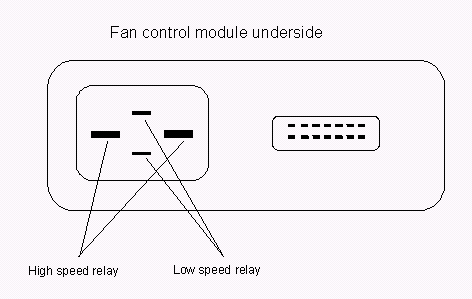
Within
the 4 pin plug there are two large connectors, they switch the full
speed wire of the fans. The two remaining smaller connectors switch the
low speed. Refer to the diagram below.
This solution works by driving the fans high speed wire with a pulse width modulated supply from a PWM speed controller.
The
speed controller is powered from the fan control module's low
speed output. So that, when the fan controller switches the low-speed
output, the fans run at low speed. When the fan controller switches to
high speed, the speed controller is bypassed and the fans run at
full speed. Power electronics are used to efficiently reduce the
speed of the fan motors without dissipating excess energy as heat.
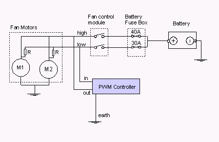
The
diagram below shows the standard two fan configuration used in the Golf
4, everything apart from the PWM Controller is standard. As you can
see, it only needs three connections to take over the function of the
blown motor resistors.
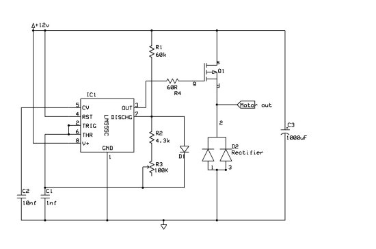
The
speed controller circuit diagram is shown below. It uses a 555 timer IC
to generate the waveform. The output frequency is about 20 khz, and has
adjustable duty cycle from 8% to 60%. In testing, it was able run the
fans fast enough to keep the air conditioning happy, whilst drawing
only 6A of current for both motors!
Interest
in ready made controllers has been quite healthy, and as a result, I
have produced a few units ready for sale. I can supply a unit for
£85.00 inclusive of VAT and delivery costs.
You can securely order one right now, by visiting the Nime Shop
here
Alternatively, email us at
Enquiries for questions concerning the product, installation or payment.
You can view the installation guide for the speed controller right now. Click here to view.