![]()
Installing Mini Cooper (R50/53)
Camber Plates
One of the
shortcomings of our BMW Mini Cooper is the lack of negative camber up front AND
weak strut towers which sometimes leads to mushrooming/deformation (more
details on that found HERE
). Hotchkis
Camber Plates address both issues. I sourced mine from Way’s online store, Way Motor Works, after getting his
feedback on pros/cons of the available types- he runs the Hotchkis camber
plates on his track car.
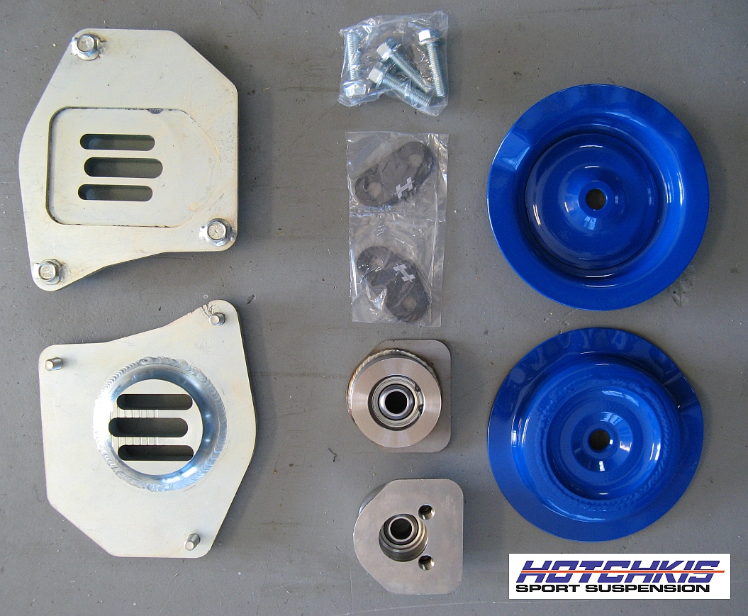
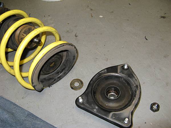
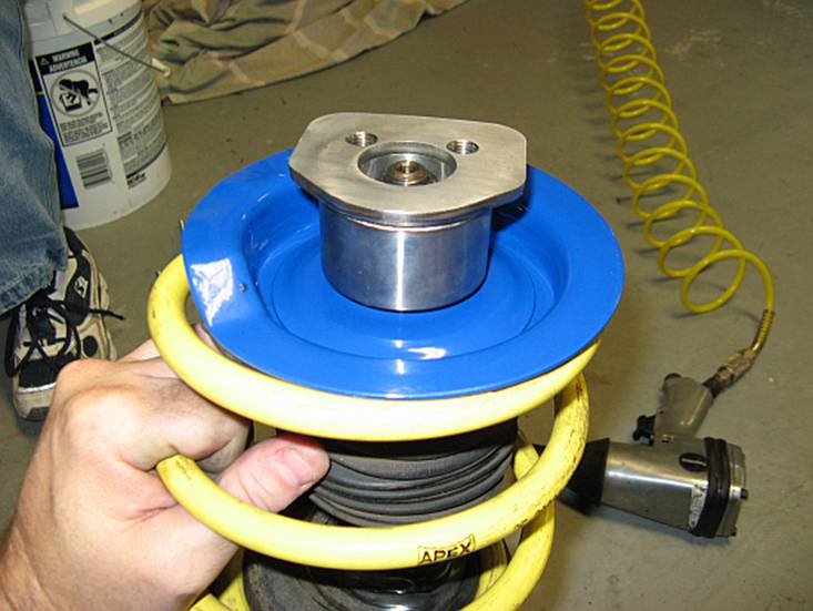
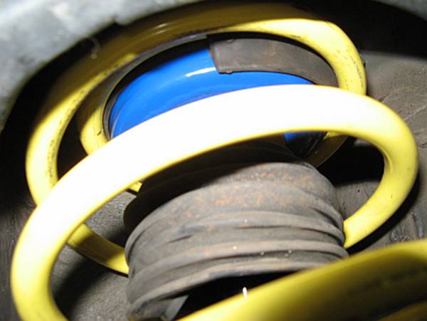
The
spherical bearings on the Hotchkis plates are replaceable and the spring hats
can be replaced if changing to a different spring type, if I change to
coilovers in the future I will just need new spring hats (blue items in below
pic).
Standard
Disclaimer: ANY USE OF THIS INFORMATION
BY YOU IS AT YOUR OWN RISK. This guide is meant to be a supplement to the
Hotchkis Installation Instructions HERE
and not a replacement.
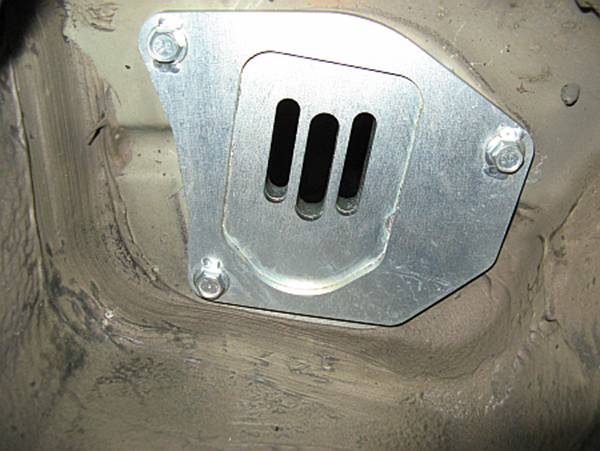
Looking at
how thick the plates are it is easy to see how they will reinforce the weak
strut tower sheet metal:
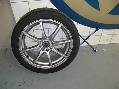
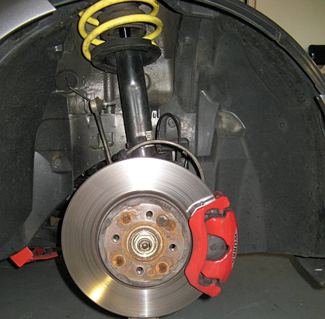
First step
is to jack up the front side that you will be working on (using jack stands of
course) and after placing jack stands under the car, removing the wheel/tire:
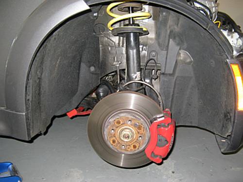
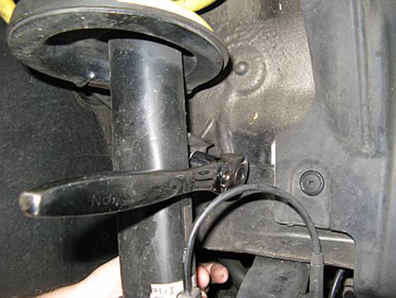
Remove the
brake line and brake sensor wire from the strut retainers carefully:
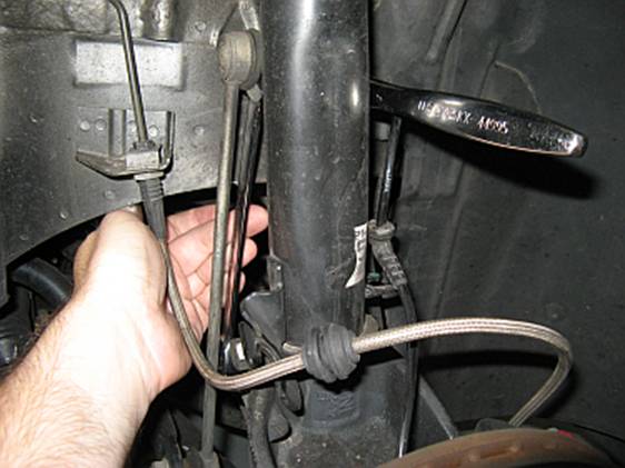
Remove sway bar endlink from strut: Use a 17mm open end wrench on the
flats behind the sway bar link joint to prevent rotation while loosening the
bolt with a 16mm socket/ratchet. Remove the sway bar link from the strut mount
after removing the bolt:
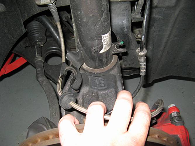
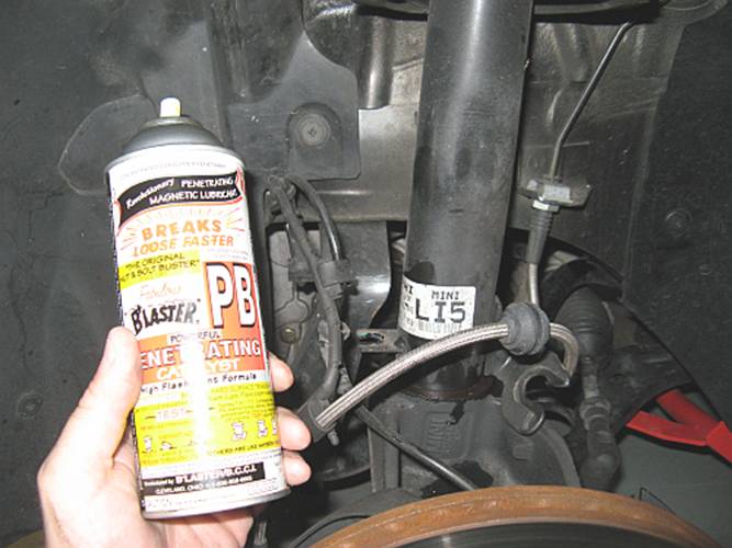
You may want
to soak the base of the strut to steering knuckle union with PB Blaster so that
it will come apart easily:
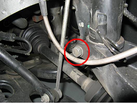
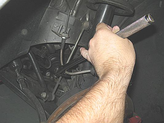
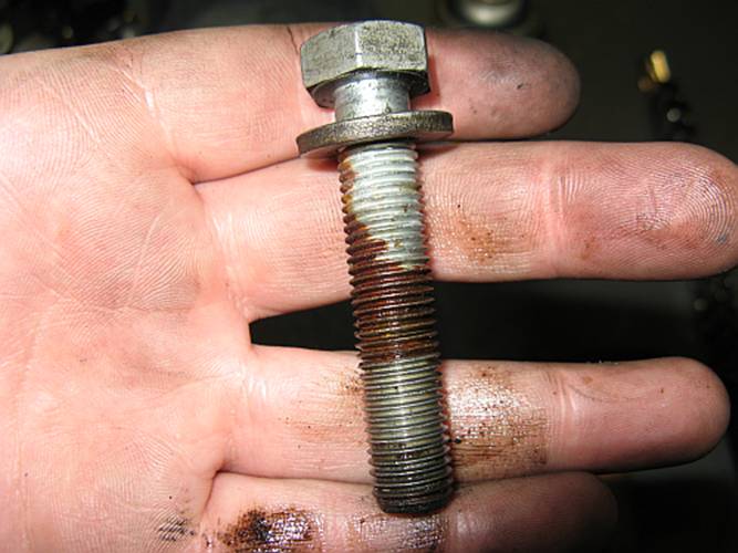
Remove the strut pinch bolt: After soaking both ends of the bolt
liberally with PB Blaster and allowing some time for it to soak in, I used an
18mm socket with a ratchet and/or breaker bar to loosen and remove the pinch
bolt. I also used anti-seize with this bolt on reassembly after reading some
nightmare stories on the forums of people breaking these off in the steering
knuckle due to rust-weld.
The
steering knuckle did drop but contrary to the Hotchkis instructions, the
knuckle did not drop enough to free the bottom of the strut- I had to compress
the suspension to remove the strut assembly after removing the three upper
strut mount nuts (next step below) in order to get enough room to clear the
knuckle. This will require some creative thinking on your part or a spring
compressor that works with the strut installed.
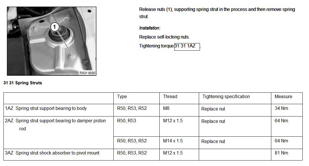
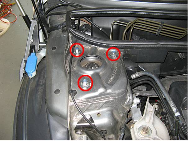
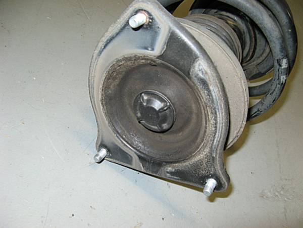
Remove the three upper strut mount nuts:
In my case this required a 13mm socket (OE nuts may be the same….or not):
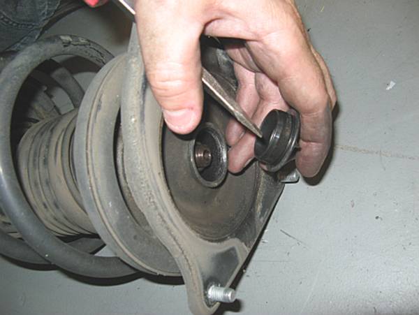
With the strut removed, the plastic cover can be removed using a standard
screwdriver to access the nut:
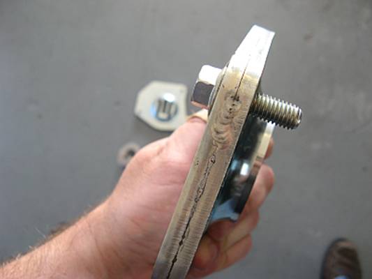
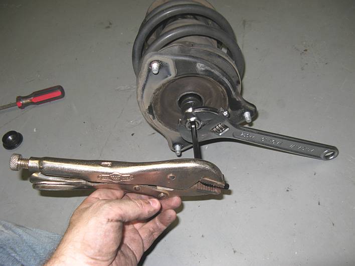
There are
some different ways to remove the nut from the strut but none work better for
me than an impact wrench, I have air but electric works too. If you don’t have
access to one of these, I have used creative solutions like the one below in
the past- a 13/16 spark plug socket and the correct HEX wrench with Vice Grips,
no guarantees this will work for everyone or every car. Pic below is merely to
illustrate a potential alternative to an air wrench, in the past I would have
cut the hex wrench down so that the Vice Grips and the wrench on the spark plug
socket were closer together, and a closed end wrench on the spark plug socket
will always work better than an adjustable:
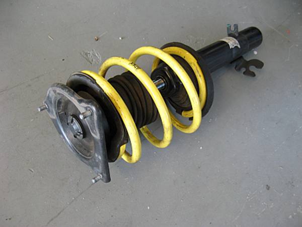
Compress
spring using a spring compressor, I have always borrowed one from a McParts
store like AutoZone using their tool loaner program:
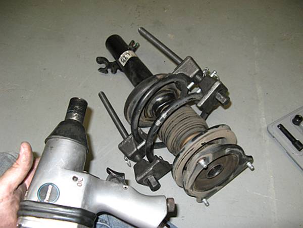
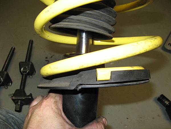
After removing
the nut you will see that there is the spring, rubber insulator, top hat,
washer, strut mount, and nut in that order:
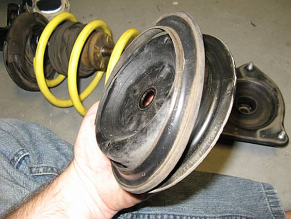
The only
items that will be re-used above the spring with the camber plate installation
are the rubber insulator and the nut. The rubber insulator is removed from the
OE spring hat and placed on the new Hotchkis spring hat:
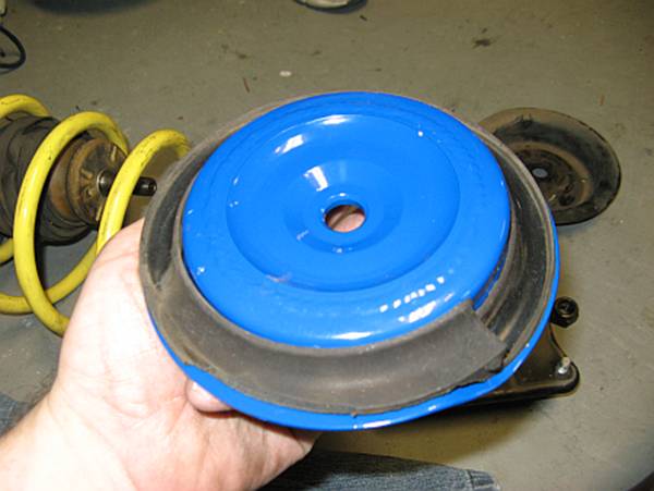
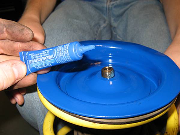
Reassemble
the spring with the new Hotchkis spring hat, now is a good time to apply some
blue LocTite to the strut piston threads. The bearing goes on top of the hat,
and the nut holds it all together.
Make sure
the rubber insulators are aligned with the base and hat stops and that the
spring is tightly aligned at the rubber insulator stops on both ends. If using
the OE springs you may need a spring compressor for the reassembly step. With
my APEX springs, we were able to use the two man method- my son loosely started
the nut while I compressed the spring by pushing down on the spring hat,
finished off with the air impact wrench:
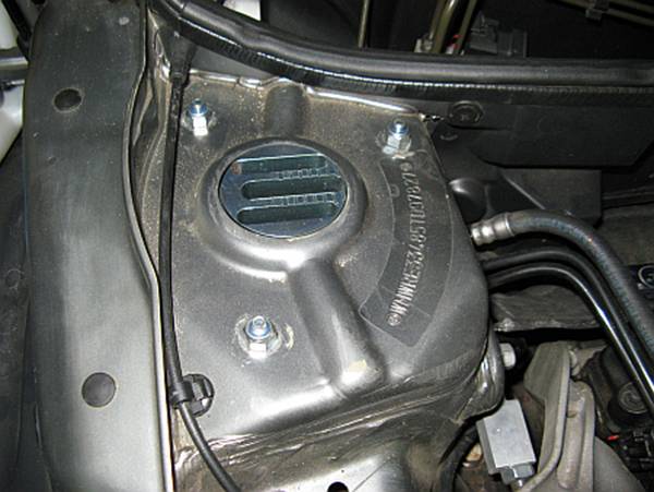
The plates
are installed prior to the strut assembly installation, they are left/right
side specific. This is also the point where you can check for possible
mushrooming issues and correct with a piece of 2x4 and a big hammer. I had some
slight strut tower mushrooming issues and the 2x4/5-lb hammer method took only
a few minutes to repair them:
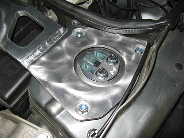
Before
attempting to install the assembly, I turned the Hotchkis strut bearing by hand
to orient it so that it would fit the plate when installed using the pinch bolt
tab on the strut housing as a reference point to align with the rounded end of
the bearing mount. It is TIGHT and will be hard to turn by hand when installing
into place. The alignment plate and bolts on top of the plate were loosely
started before tightening everything up, Hotchkis suggests using blue LocTite
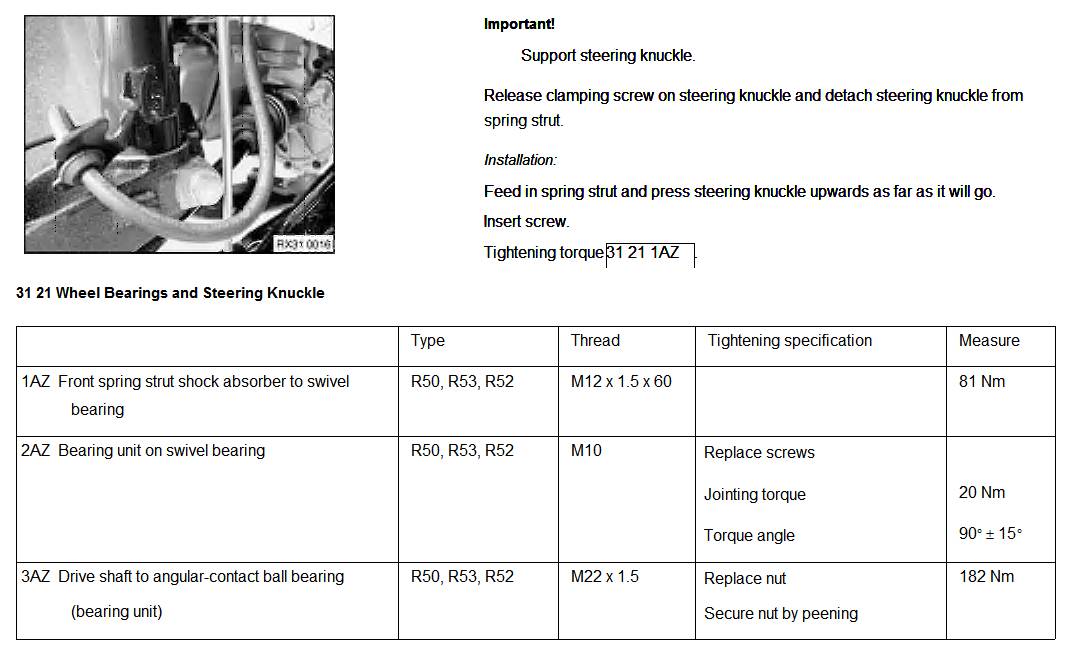
on these bolts. TIS torque specs at bottom of this write-up for your reference,
installation is reverse of removal. Don’t forget to secure the brake line and
brake sensor wire on the strut:
TIS Instructions and Torque Specs: