![]()
My Lotus Elise ForcedFed Header Installation (Bill Henderson, 01-06-07)
![]() Standard Disclaimer: The following is my experience
provided for informational purposes only, any use of this information by other
parties to conduct installation is at their own risk, no
warranty/guarantee that information is accurate is expressed or implied.
Standard Disclaimer: The following is my experience
provided for informational purposes only, any use of this information by other
parties to conduct installation is at their own risk, no
warranty/guarantee that information is accurate is expressed or implied.
Tools Used:
- Rhino
Ramps
- Low-profile
Jack
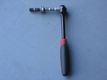
- Small
Head Ratchet (Husky Pro), Socket Handle, and Breaker Bar
- Swivel
Extension
- Metric
Sockets
- External
Torx Sockets
- Metric
Wrenches (GearWrench preferred)
- Adjustable
Wrench
- Needle-nose
Pliers
- Rubber
Mallet – useful for aligning exhaust
Time: 4-5
hours dependent on skill level
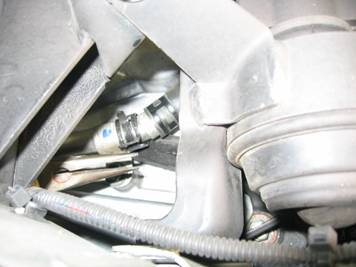
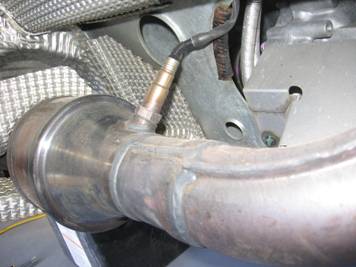
Steps prior to ramps: There are a few things I did prior to getting the
car on the ramps. First I jacked up the car on the passenger side and removed
the rear wheel and wheel liner (5 plastic screws); this provided access to the
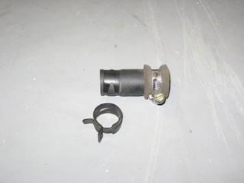
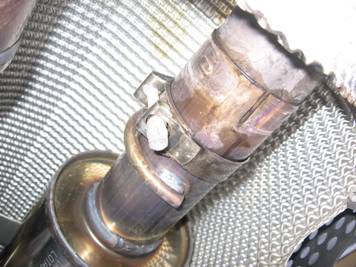
air injection tube. Using needle nose pliers I removed the clamp for the cap on
the end, and then pulled the rubber hose off:
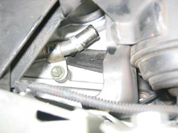
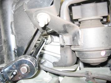
Next, I removed the bolt
holding the tube to the motor using a ratchet and a swivel extension:
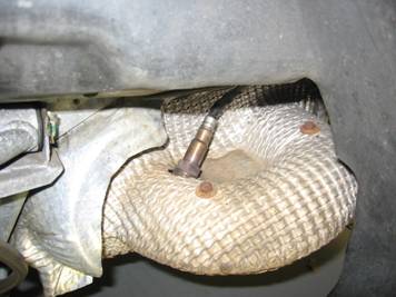
The wheel and wheel liner
were reinstalled and the jack was moved to the driver side and that wheel was
removed for access to the post cat O2 sensor. The O2 sensor was removed and
left hanging:
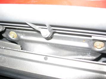
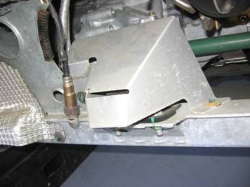
The trunk was opened and I
removed the upper exhaust manifold heat shield bolts (2) on top:
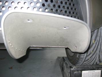
Steps after the car is on ramps: The car was then backed on to a set of Rhino Ramps
for lower access. The diffuser panel was removed (3 bolts on each side, 5 bolts
under the license plate, 2 large bolts towards the front of the car, and 5
small bolts where the diffuser joins the other lower plate:
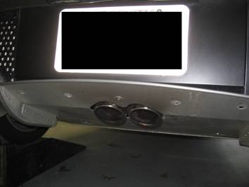
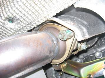
After the diffuser was
removed the exhaust clamp was loosened, and the passenger side exhaust mount
hanger bolts were removed so that the exhaust could be removed:
The driver side exhaust
hanger bolts were loosened a little (but not removed) and the exhaust was
carefully dropped under the car to the ground and moved to the side:
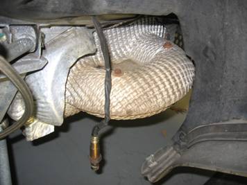
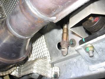
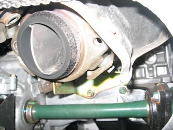
The next item to be removed
was the pre-cat O2 sensor, once removed it was left hanging:
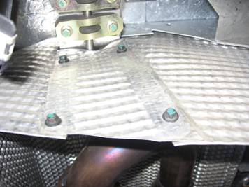
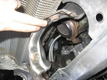
The catalytic converter can
now be removed by removing the 2 spring tension bolts that hold it to the
exhaust manifold (the riveted heat shield was not removed for use with the new
header). The upper heat shield lower bolts (2) were also removed as seen in
first picture below:
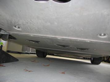
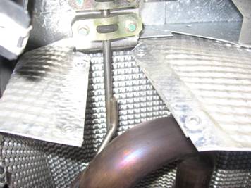
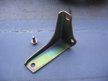
The lower
engine/transmission mount heat shield is now accessible, 2 bolts hold it to the
frame:
The lower exhaust manifold
mount can be removed, one bolt on the manifold and two bolts on the engine
block:
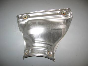
The upper exhaust manifold
heat shield is removed, kind of like a puzzle - be patient, it will come out in
the right position without bending or cutting:
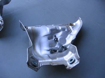
Next, the lower exhaust
manifold heat shield bolts (4) and heat shield were
removed. This one was a little tougher than the upper heat shield as there was
not a lot of room to maneuver but as above, treat it like a puzzle and be patient, it will come out:
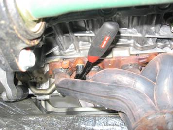
Only thing remaining is the
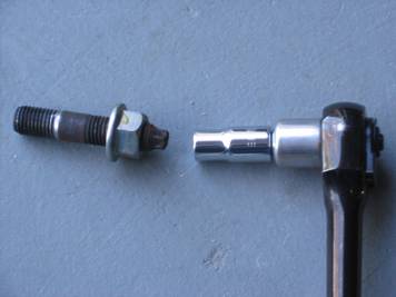
exhaust manifold bolts/nuts: Two Torx head studs with nuts on either top side, one bolt top middle, and two lower bolts.
Using a combination of ratchets, socket handles, and bars all of these can be
removed. By first loosening the nuts on the Torx head studs, the tension is
removed and then the Torx socket/ratchet can be used to remove the studs. This
is necessary to provide clearance to remove the exhaust manifold with the air
injection pipe intact. NOTE: The Torx socket used is a size E8:
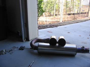
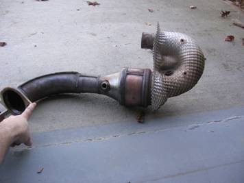
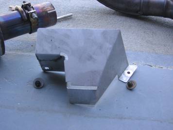
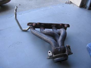
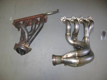
The exhaust manifold is
removed from the bottom of the car, it may take a few tries to get it in the
right position to work the air injection pipe out between the tensioner and engine but it is possible. Compared to the
new header, the welds in the collector are noticeably cleaner and the pipe size
is larger:
The Torx head studs are
reinstalled:
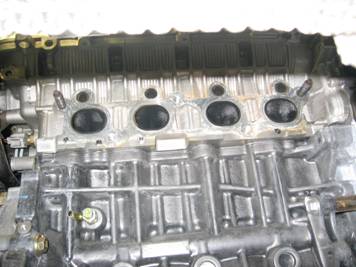
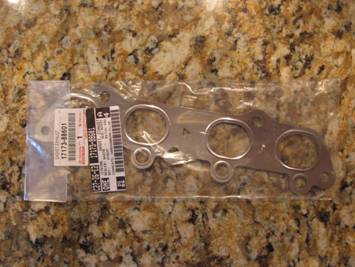
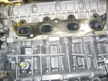
The old exhaust manifold
gasket was removed and a new one installed. This gasket is a crush gasket and
it is good insurance to replace now, it only cost $20 at the Toyota Dealer, P/N
17173-88601. This gasket was reinstalled the same way the original was, with
the arrow in the center pointing towards the passenger side:
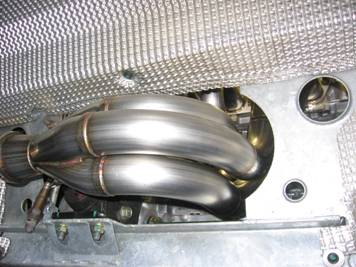
The header can now be
installed, there is even less room to work than there was before. The top nuts
and bolts can be accessed with a torque wrench (spec is 37 ft-lbs); the bottom
could not so I tightened those by feel with a small ratchet. The exhaust
manifold heat shields are NOT reinstalled:
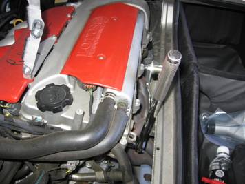
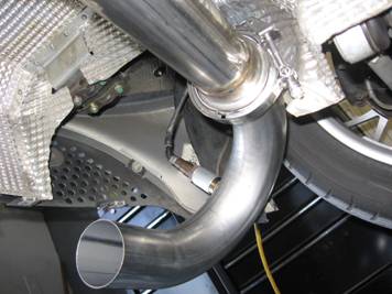
The test-pipe or high flow cat
is attached to the header with three springs, I found it easiest to hook 2
springs while the pipe was at a 90 degree angle to the header and then to
stretch the pipe into place, this only left one spring to wrestle with pliers
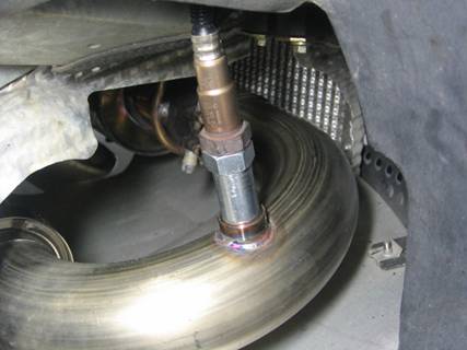
to get in place. The post-cat U-pipe was installed with supplied clamp and the
O2 sensors were reinstalled as well. I used the GPMoto
CEL fix which extends the post-cat O2 sensor away from exhaust flow to prevent
the Check-Engine Light (CEL) from coming on due to a test pipe or high flow cat
install (see note UPDATE at end of article for this CEL fix issue):

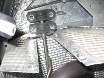
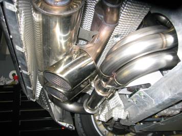
The exhaust reinstalled
(exhaust clamp and hanger bolts/hardware) along with the lower
transmission/engine mount heat shield:
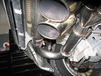
I test fit the diffuser and
used a rubber mallet to position the exhaust within the diffuser cutout before
tightening the clamps. After making sure the clamps were tight and everything
lined up, the diffuser was reinstalled and the car was left to idle for 15
minutes to give the ECU a chance to adjust to the new header.
Time for a drive to see if
all the work paid off (may not want to be too hard on the car for some miles as
it may run a little lean until the ECU has some time to adjust the fuel
maps)…….. ![]()
![]()
[UPDATE] The GP Moto CEL fix did not work (error
"P0420- Catalyst System Efficiency Below
Threshold" every 50 miles) but I have found a few options:
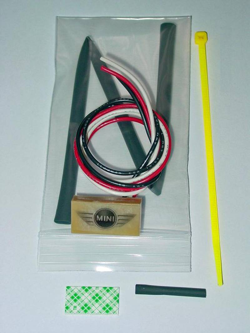
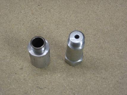
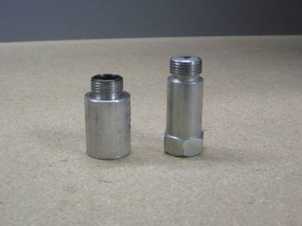
1)
I have found another mechanical CEL fix (different
design) that has worked for the past 300 miles and no CEL, available on eBay
from seller strutking. It is a much lower cost option
than the first one I tried and works much better. I did have to drill some for
additional depth but communicated this to the seller and he has told me that in
the future he will make them a little deeper (about ¼” deeper than other
applications). GP Moto on left, strutking on right:
2)
Other people have had de-cat success with the Mini
version of this electronic O2 simulator from www.o2sim.com
: