This
installation guide provides an example installation of our Fan Speed
Controller into a VW MK4 Golf. These instructions may be suitable for
other cars based on the same platform (i.e. Seat, Scoda, Audi etc) it
will be left to the discretion of the reader to determine whether this
installation would be suitable.
The
installer should be familiar with basic electrical wiring principles,
and know how to make good connections and use insulating materials.
Become
familiar with the speed controller and it's three connecting wires.
They are colour coded as Brown, Blue and Green, and have the following
meanings.
|
Wire
|
Meaning
|
| Green/Yellow |
This is the ground connection. It should be connected to a good earthing point in the car. |
| Brown |
This
is the supply connection. It should be connected to the
low-speed input of the fans. In this example we have connected to this wire at the
existing fan control module. |
| Blue |
This
is the fan output connection. It should be connected to high speed
input of the fans. In this example it is connected to the high speed
fan connection on the existing fan control module. |
Once
the earth is connected, there are only two wires to worry about. The
brown wire should go to the low-speed fan connection. The blue wire
should go to the high speed connection.
The
installer can choose where to make these connections. The low and high
speed wires can be connected near the fans from under the car. Some
people prefer this approach as is only touches wiring that is
replacable with the fans.
The
other approach is to wire directly to the loom that connects to the fan
control module. This approach is easier, as it does not require access
from underneath the car which usually means a quicker job. The only
drawback with that, you will have to connect to the exisiting wiring
loom. This is the approach used here.
Locate the battery and remove the cover.
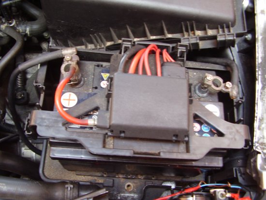
Figure 1. Battery exposed showing fuse box.
Disconnect
and remove the battery. Remove the battery fuse box. You can see the
battery box in figure 2 below. It is made of a non metalic material and
mounted to the car by the four bolts shown. Remove these bolts, and if
present, remove the 10mm bolt securing the battery box to the air
filter housing.
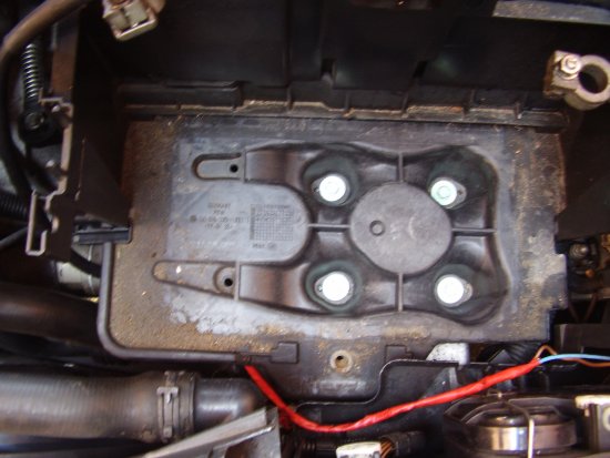
Figure 2. Battery removed
With
the battery box removed, it is possible to undo the two bolts holding
the fan control module to the battery tray. The bolts are located
in the bottom-left corner of the tray. They have already been removed
in figure 3 below.
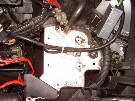
Figure 3. Battery tray visible
With
the fan control module bolts removed, carefully manouver it out from
under the tray via the left hand side near the starter motor. Remember
the direction of fitting of the controller.
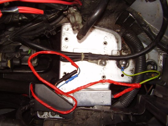
Refering
to figure 4 below, look at the fan control module and identify the
supply and fan wires indicated in the picture. The nearest wire in the
middle of the left hand connector is the low-speed fan supply. You need
to connect the brown wire from the speed controller to this wire. You
do not need to cut the wire. Simply remove some of the insulation from
the supply wire and solder the brown wire to it, and cover the
connection with insulation tape. If you can't solder, you can try
using a press-on type connector like 'scotch
locks' from Halfords. Failing that, you can simply bear enough copper
wire from the brown wire to wrap in round the supply wire a couple of
times and twist to secure.
Now
locate the high-speed fan wire on the right hand side. This is a heavy
duty wire, as it needs to be up to the job of supply both fans with
full power. Carefully remove some of the insulation from this wire, try
not to damage too many copper strands.
Connect
the blue wire from the speed controller to this wire. This wire is
probably too thick for scotch locks, so they are not recommended here.
Either solder, or bare enough copper from the blue wire so that you can
wrap it once or twice around the thick wire and then twist together
until secure. Insulate with tape.
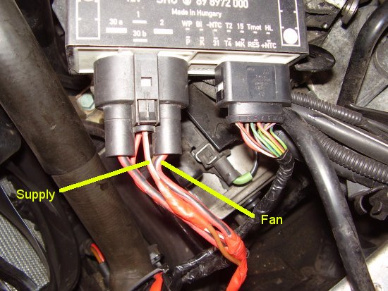
Figure 4. Fan control module connections
Connect the earth wire to one of the existing points. I have used the centre one.
The
black device on the brown wire is an inline fuse, rated at 10A, and is
there to protect the rest of the cars fuses and wiring should a fault
occur in the speed controller.
There
is a crimp on blue connector and socket inline with the blue wire to
the fan connection. These together allow quick disconnection of the
device.
The whole box is stuck smooth face down to the battery tray using double sided sticky pads.
The
speed controller will fit comfortably on the battery tray underneath
the battery box in the location shown in figure 6 below.
At
this point it would be worth temporarily re-connecting the battery,
ensuring that there are no loose wires near any moving engine parts,
and starting the engine with the air-conditioning on. The fans should
begin to turn at the low speed setting. If this is not the case, refer
to the trouble-shooting section.
If all is well, turn-off the engine. Remove the battery and then.