|
Joined: Tue Feb 15, 2005 1:44 pm
Posts: 4148
Location: San Diego CA
|
This install can be accomplished
by a good shadetree mechanic. However, if you do NOT have a full set of
metric wrenches, including extensions of different lengths and including
wrenches with indexable angled heads for tough to reach spots, then you
should have a licensed mechanic do this installation for you. Read all
instructions and examine the photos below before you begin so you know
where you are going!
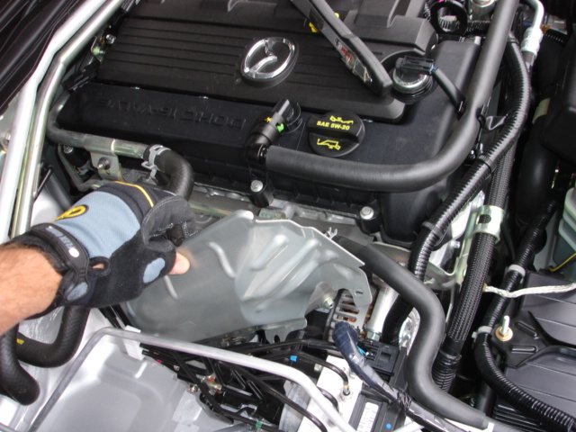
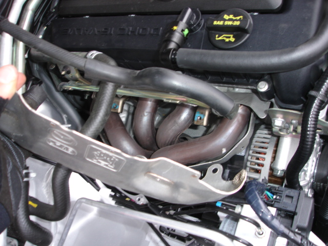
First, place the car on ramps or jack stands (NOT JUST A JACK). Remove the
outer chassis-mounted heatshield shown in the picture below in my hand. It
is important to wear gloves for this install because the heatshield edges
can be razor sharp! This item will be reinstalled so place it safely aside
with the hardware that connects it to the vehicle. If equipped, remove
passenger side and center portions of the strut brace.
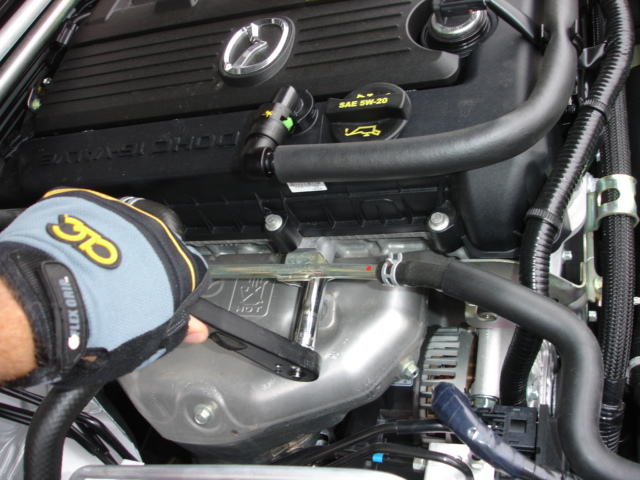
Remove radiator cap to relieve pressure on the system and then unbolt
heater coolant line from above exhaust manifold and disconnect the line by
using a wrench to pull off the clamp you can see here to the right of my
hand. You will drip about a quarter cup of coolant from this high point in the
engine bay, I used a small shallow bowl to catch this fluid when I opened
the connection.
Pull the battery cover (you see here my race battery which is smaller than
your standard battery). To create more space to get the factory header out
you need to disconnect this small plastic hose clamp. Notice that it is
reuseable so you don't want to break it. You can pry it open with just your
fingers, no need to use a wrench on it. Save it because you will be
installing it again at its original position.
Now that you have created some space, remove the heatshield from the
factory header. It is two parts and the upper "cap" part is held
on by numerous little 10mm bolts. Neither part of this shield is reused.
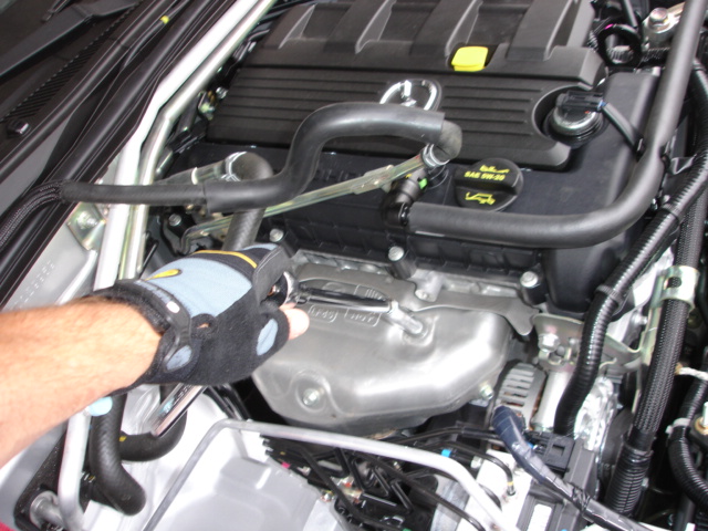
Continue removal of the factory heatshield by removing the lower portion of
the heatshield. You will need to bend it slightly to get it out but it will
easily bend back to original position. This gives you access to the 15mm
nuts that hold the header to the motor. Spray the nuts with WD-40 and leave
for an hour. Do the same with the 14mm flare nuts under the car that hold
the spring connection between header outlet and midpipe (don't spray where
the studs connect to header on this downstream connection...just the nuts
on the end of the studs against the springs). There is a third connection
point between the head and the outlet, to a bracket...spray those two 15m
nuts too.
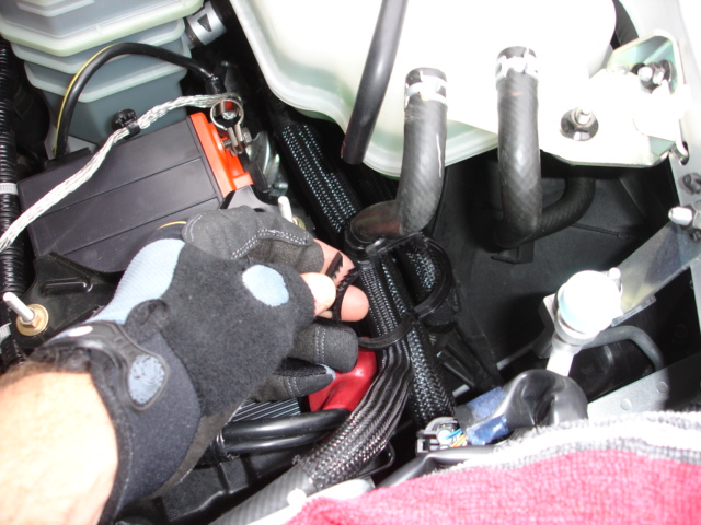
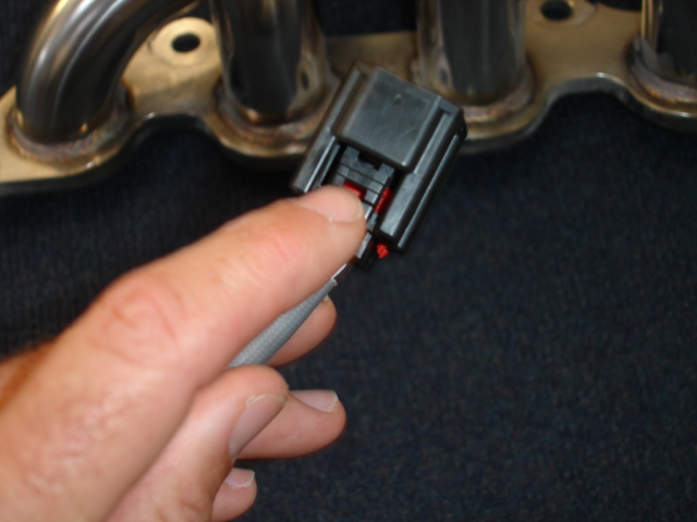
Crawl under the car (which again...should be on JACK STANDS or ramps but
NOT JUST A JACK). Remove the 5 bolts that retain the cover plate plate
directly below the oil pan and factory header to get access to the O2
sensors. Remove the plate for access. Unplug the two O2 sensors. Note these
are simple plugs that each have a release button which I have my finger on
below. All you need to do is squeeze that button with your thumb while you
grip the plug to release each plug. You do this by reaching up from below
the car. Note that we have no O2 sensor connection in our header....in part
to keep flow as clean as we can get it but also because we could see no
purpose in locating them in the header since doing so will throw a code
because pulling the factory header includes removal of the first catalytic
converter. THREE choices on what to do with the O2 sensors with our header.
Choice ONE is to simply leave them out of the car and you will throw the
same codes as if they were in the header....but run the default
"safe" map which is a little too rich. Choice TWO is a much
better choice which is to buy our midpipe which is designed to take both O2
sensors...and includes two O2 sensor connections...one before the midpipe's
converter and one after the midpipe's converter to help avoid a code but
you need to extend the wires to reach these locations (we now have an
extension cord for the first O2 sensor which does provide fuel trim to
information to the ECU which is why having at least this first sensor
installed is your GOOD IDEA). Note that the Racing Beat extension cords use
a thermal jacket to protect the wires but you must route them carefully
because the plastic plugs on the ends WILL MELT if in direct contact with
exhaust). Third choice is equal to the second choice but takes more work:
have an O2 bung welded by your local muffler shop before and after the
factory second converter in the factory midpipe to replicate the setup we
are doing with our midpipe. Choices two and three require extension of the
O2 wires and our friends at Racing beat are working on a "race
kit" set of extension wires (first and MOST important SHORT extension
wire now available on our website) so customers with their header (or ours)
can make choice two or three without splicing the wires.
Remove the 15mm nuts which hold the header to the motor. Again use some
liquid wrench on the 14mm nuts that hold the lower connection to the
midpipe and remove with 14mm long socket the nuts and studs. There is
another connection point about 5 inches up from the downstream
connection...remove the 14mm bolts that hold the converter to the heavy
steel bracket at this point and remove the bracket which will not be used
again (it supports the substantial weight of the factory converter and is
not needed for the much lighter header you are installing).
The header can now be removed. HOWEVER, HERE IS THE KEY TO MAKING THIS
PROCESS EASY. I removed the factory header several times without doing this
next step and it was very difficult until I figured out that you can easily
tilt the alternator forward by removing two bolts...and with the alternator
tilted forward the factory header assembly will come out easy.
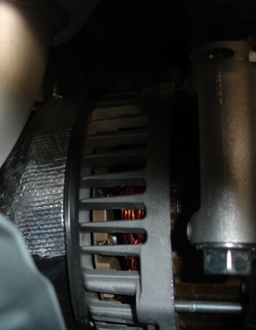
The alternator has three 14mm bolts holding it to the block, one bolt on
top and two on its underside. Back out (without removing) the underside
bolt in the very bottom left of the picture below.
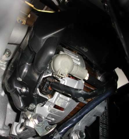
Then back out the top 14mm bolt (without removing) and the alternator can
be tilted forward and the factory header easily pulled out.

Now the factory header can be easily removed!

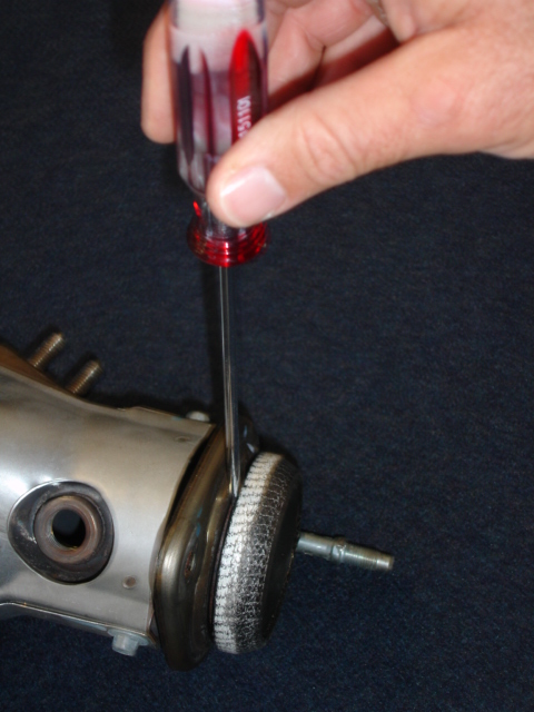
The factory gasket for the header connection is reused. The factory gasket
for the downstream connection is also reused...just use a very thin edge
(such as on a small flat tipped screw driver) to GENTLY pry it off the
factory header as shown and then slide it onto your new header.
Before installing your new header cut the provided thermal tape into two
pieces. This tape is provided for the alternator rear case. We tested the
header without doing this step with a temp probe on the alternator and never
found the temperatures reached levels of concern with the first primary
tube a good inch above and behind the alternator but in an abundance of
caution we use this tape to give the alternator's protective case some
extra protection. Clean the black plastic protective case on the rear
section of the alternator and cut the tape into two pieces. Remove the
backing and apply this thermal reflective tape sections side by side to
cover the portion of the rear alternator case that will face the first
header primary.
Congrats, the hard part is done. Now drop the new header into place
aligning the outlet to the midpipe connection below and finger tight the nuts
that hold the header to the head using liberal amounts of anti-seize
compound. As you likely noticed in removing the factory header, the lower
connection is a spring loaded connection that uses nuts on studs. You
removed the nuts from the factory header and now you remove the studs (if
you have not previously done so) and springs and add them to your new
header in the same manner as they were installed on the factory header.
CAUTION: If you slam the nuts all the way to the top of the studs during
install you may find it very difficult later to get the nuts separated from
the studs...if this happens you can take that stud to your local autopart
store and get a replacement if they have the same (not likely) or a metric
threaded bolt of the same spec and slightly longer (at least quarter inch
longer) to make install with the spring connection easier---again use
liberal amounts of anti-seize. Torque manifold nuts to 25 ft/lbs. Torque
the downstream sprung connection (yes, you want the springs compressed) to 17ft/lbs.
Reinstall main heatshield and reconnect coolant pipe above header as
before.
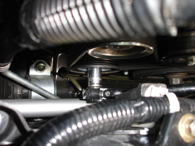
Picture below shows the only way you are going to get the alternator back
into position. You need to take the tension off the belt. Notice that the
spring loaded tensioner is the pulley immediately under the alternator
pulley. You need a 14mm socket on a long wrench to reach it and then apply
torque clockwise (pushing wrench toward driver's side headlight) to take
the tension off the belt so you can thread your alternator bolts back
in...having a buddy at this point is helpful.
Reinstall cover plate under the car and torque nuts to 18 ft/lbs. Now
reconnect coolant line and attach it again to engine block with original
hardware, reorient the line as originally installed including the plastic
clamp that holds it organized up by the overflow bottle. Install the main
heatshield again which protects the brake lines from radiant heat.
Now drive and have some fun....check torque after 100 miles on all nuts
involved in this installation.
_________________
Brian Goodwin
Good-Win Racing
www.good-win-racing.com
Last edited by Brian on Fri Jul 03, 2009 1:32 pm,
edited 4 times in total.
|
|
