Mirrored from:    http://forum.miata.net/vb/showthread.php?p=4703239

 MX-5 Miata Forum                                             


MX-5 Miata Forum > MX-5 Miata Discussion > NC (2006+) > NC Performance and Tuning - Engine

Full GWR Exhaust - Install Instructions (pic heavy)


NC Performance and Tuning - Engine If you need more power than the car was built with, this is the place. Aftermarket parts and tuning from simple bolt on parts to total high performance engine builds.


Description: Description: Old12th August 2010, 04:34

  #1

msstavros

Supporting Member


Join Date: May 2007

Location: Greece

Posts: 112

Full GWR Exhaust - Install Instructions (pic heavy)


This is an attempt to present a step by step installation guide for the full GWR exhaust (headers, mid pipe and rear silencer). Most of the information is available through GWR forums and miata.net postings, but I have tried to present a more complete guide, after having completed the install myself, following the guides / information floating around. Apologies for the huge posting, and the large pictures.

First of all, let me start by sharing with you that I am not a professional mechanic, I know basic stuff and have some tools but really never changed a header before in any car. Have striped a bolt or two (not on the MX5), and that is all. Having said that, most people and Brian say the install is doable by a good shade-tree mechanic, within 8 hours. I could not do it within that time frame (more like 12-15 split across several days), mostly because of things not going the way they should, and of some hidden difficulties. I have also taken my time, did not want to rush things, and also did some cleaning of the underside while everything was off the car.

The tools/items that you will need are:
1) Wobble Socket Extensions. These will come handy for reaching difficult bolts on the header, alternator, outer header heat shield.

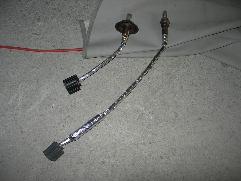
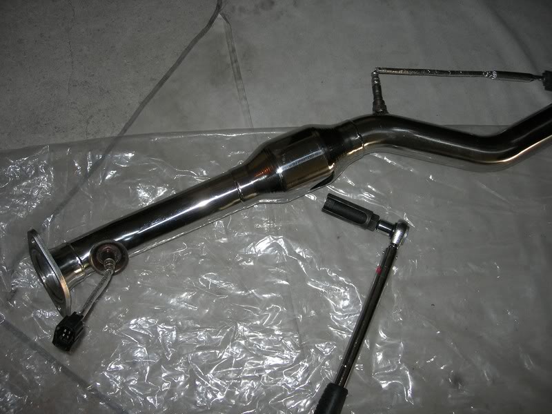
2) Oxygen Sensor Socket. This looks like a 22mm deep socket, with a cut along one of its sides. Some people do the install without it, but it is better to have it. You may be able to borrow it from a friend. You should have it to avoid damaging the first O2 sensor, which is by the way, mighty expensive to replace! This sensor has a dish around its base, which makes it quite difficult for an open end spanner to safely grip the sensor.

3) Offset ring spanners. Again may come handy for the header bolts. If not a set, at least a 15mm one for these bolts.

4) Ring/open end combination spanners

5) Good set of ratchets. A small, and a medium length at least, and quality sockets.

6) Deep socket set

7) Anti-seize compound. I used Molyslip Alumslip on all the exhaust bolts. A painter's flat paintbrush No. 6 will be handy for application.

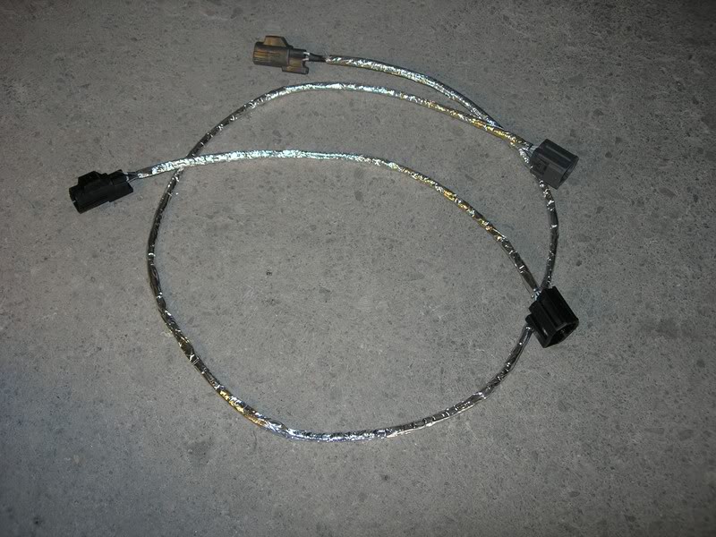
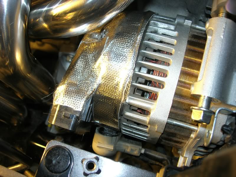
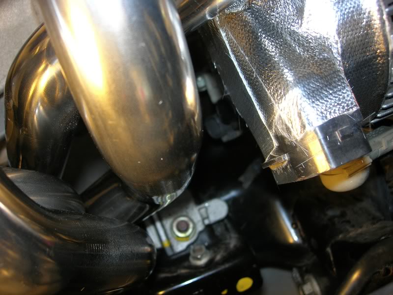
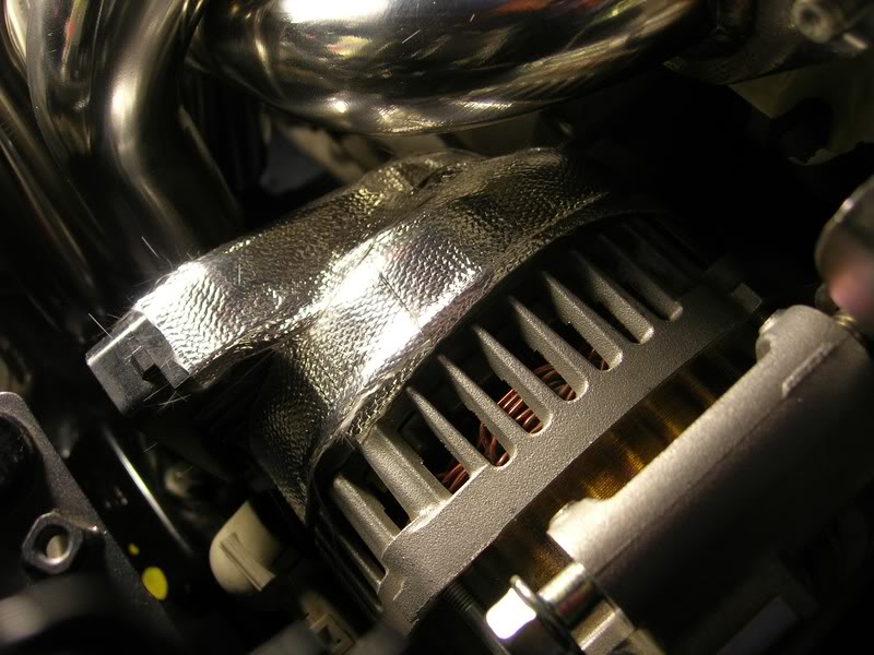
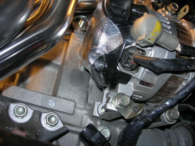
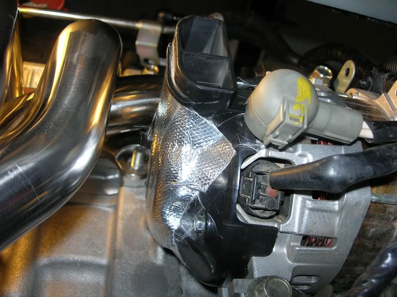
8) Some thermal tape and optional aluminum tape. I used the thermal tape for covering the alternator back housing, the outer (brake lines) heat shield and for protecting the O2 sensors wires. The latter is optional, and probably an overkill, but it is better to be safe than sorry! Aluminum tape was used on top of the thermal tape on the cables. This not only heat proofs them, but also makes them stiff, so they can retain the shape you will give them.

9) Bent needle nose pliers. These will come handy when removing the two fasteners holding the catalyst heat protective material under the car to pass over the cable of the second O2 sensor. Alternatively, if available, a y shaped tool for removing trim fasteners. Unlike the plastic fasteners in the fender wells and in the trunk, those two on the underside heat shield are quite firm and require a tool. The heat shield itself is easily damaged, so extra caution should be taken when removing them.

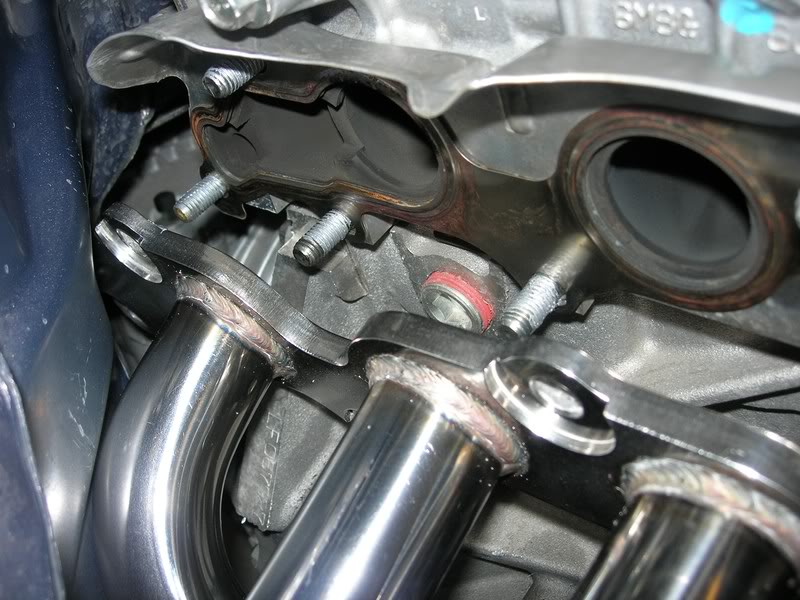
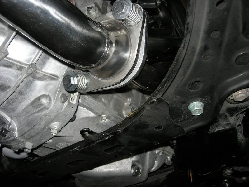
10) 2 high tensile bolts and washers (Optional). I used high tensile, grade 8.8 black bolts and heavy duty stainless washers (30mm outside diameter, 11mm inside dia., 2mm thickness). These will be required for the connection of the mid pipe to the header. Normally you can use the factory studs, but mine came off with the nut stuck on them. If you have a vice grip, you may be able to undo the nuts from the studs. Otherwise just buy the bolts and washers. Make sure the bolts you buy are fine pitch (1.25mm)! Length should be 70-75mm, 10mm dia.

11) Torque wrenches. This may be optional, and totally up to you. Personally, I like to know that any bolt that was touched, is again fastened to the specified torque. I could not manage to use it on all the header bolts, but it is a good tool to have to get a feel at least on how much torque each bolt/nut requires. I used an expensive model, and a smaller budget one.

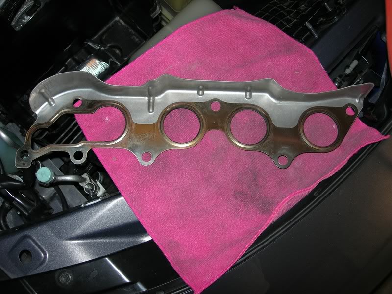
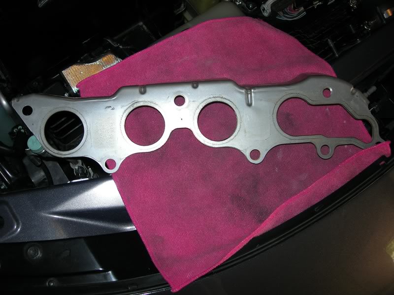
12) Header gaskets (Optional). Normally you will not need to change them. While trying to remove the old header from the car, I managed to place a small dent on the bottom ring gasket though. I did not want to take any chances so I bought a new one (Part number: L315-40-581). The cylinder head side gasket was reused (only 23K Kms on that). Bare in mind that although in US the ring gasket is around $25, here in Greece the price was 62 Euro! Therefore, best to check with your local parts shop if you are not in the States. To avoid buying the gasket altogether, REMOVE IT BEFORE YOU START TO PULL THE FACTORY HEADER OFF THE CAR!

13) 2xBolts, 2xNuts, 4xWashers, 2xspring washers. All stainless. Length of bolts should be 45mm min, diameter 10mm. These will only be required if you only have metric spanners/sockets. The Q exhaust uses US size and thread bolts and nuts, and although a 16mm will safely hold the bolt, the nut is something between 17 and 18mm.

On to the install:

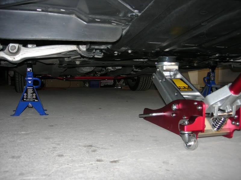
Start by unbolting the lugs on the front passenger side wheel. Do not remove them just unbolt them. Raise the car and place on jack stands. Ideally you can use 4 jack stands for maximum clearance when working under the car. I did not have two sets, so just two were used on the front jacking points. Hand-brake applied, car in gear, rear wheels choked.

SAFETY FIRST!!!!!!!
MAKE SURE THAT YOU DO NOT USE JUST JACKS TO RAISE AND KEEP THE CAR OFF THE GROUND !!! ALWAYS, ALWAYS USE JACK STANDS!!!! NEVER EVER WORK UNDER OR AROUND A CAR SUPPORTED ONLY BY A JACK!


Remove the wheel and place aside. Working in the engine compartment, remove the strut tower bar if you have one. Since a lot of fasteners will be removed, it is a nice idea to have some ziploc plastic bags to keep all the fasteners for each component removed, safe and labeled.

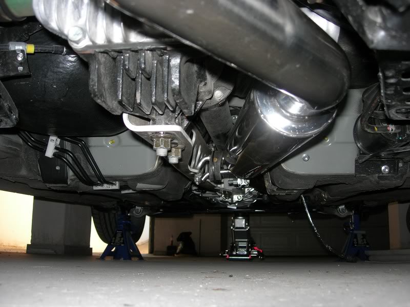
Working on the underside of the car, remove the oil pan protector plate. It is held in place by 5 bolts (12mm). Place your jack under the oil pan, and raise it until you feel some weight resistance. You do not want to raise the car, the jack is there just as a precaution. Paranoid maybe, but you can never be too safe! Alternatively, if you do not feel comfortable with the oil pan, place the jack in the middle of the front cross member (this is the front jacking point indicated in the WSM, under the differential for the rear).


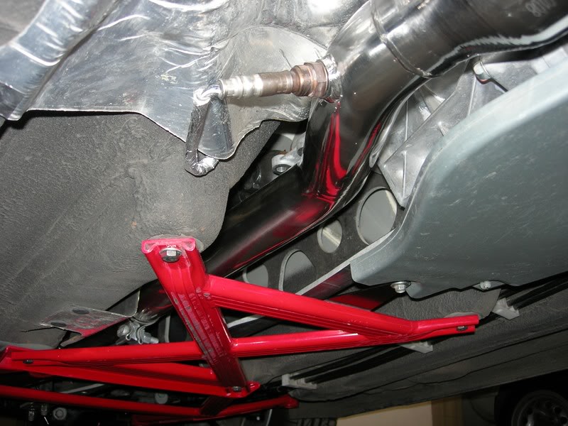
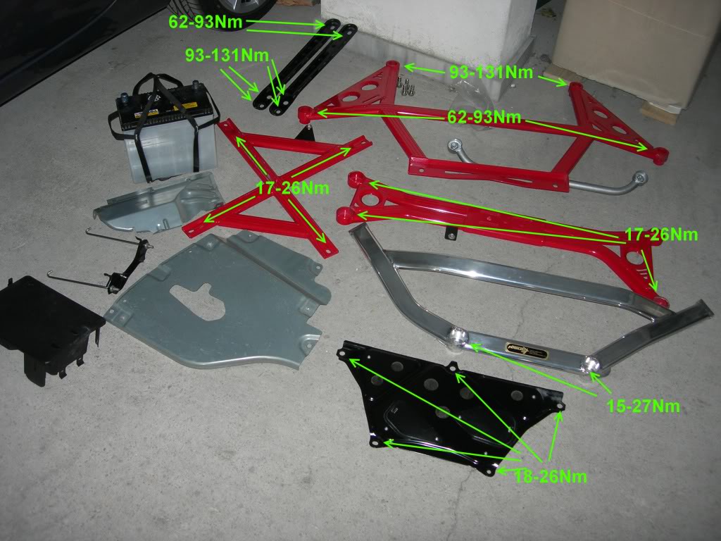
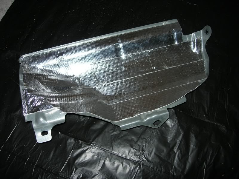
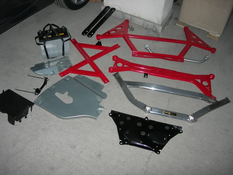
Again working under the car, remove the front member bracket, cross brace and if equipped transmission tunnel heat shield/protector. If you have any other added under braces, all these should also be removed. Working inside the engine compartment, unhook the heater hose from the side of the battery cover and remove the battery cover, J-hooks, battery and battery box. I did not manage to remove the live battery cable from the box (it is held by some really stubborn fasteners) so I just moved it forward. Remove the cable from generator mount. This obstructs the generator's air duct bolt.

Description: Description: http://i928.photobucket.com/albums/ad121/msstavros/GWR%20Exhaust/DSCN1498ed.jpg


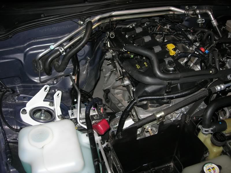
The following picture shows all the items I removed:

Description: Description: http://i928.photobucket.com/albums/ad121/msstavros/GWR%20Exhaust/DSCN1568.jpg


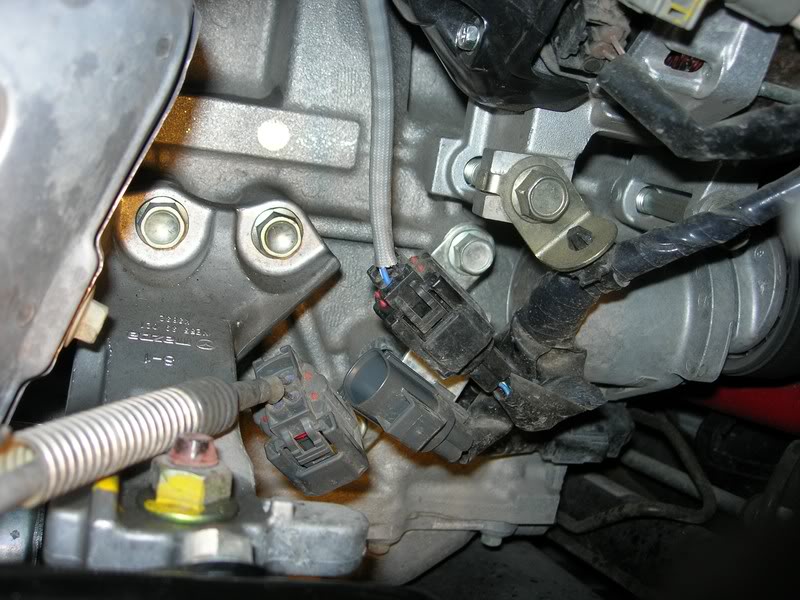
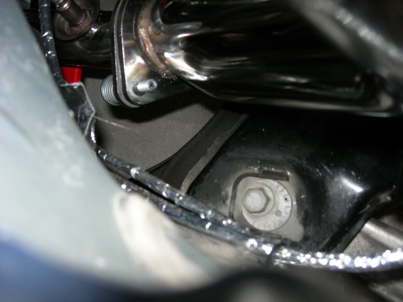
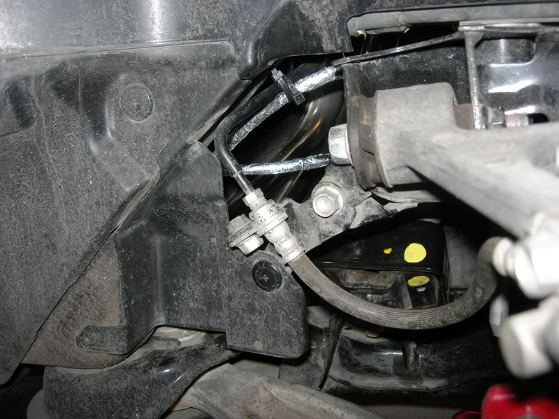
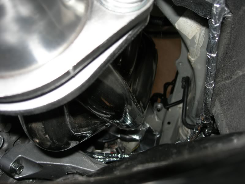
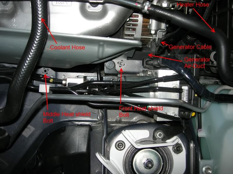
Below the battery is the outer (brake line) heat shield. In order to remove that, you have to work under the car, near the passenger's lower wishbone. There are two bolts that have to be removed, the middle and the front one. Both are 10mm. Use extensions (I used 3) on a ratchet to reach the bolts from under the car. The front one is hidden by the alternator's air duct. From the top, undo the 10 mm bolt holding the duct and place it aside. You can now remove the front outer heat shield bolt. Do not mix it with the ABS bolt (it is a 12mm). Remove the rear nut and recover the heat shield.

Open the radiator cap to relieve any pressure, and close it again. We are going to remove the coolant line above the header. Undo the clip holding the heater hose in front of the car on the left of the coolant overfill tank. The clip is reusable so do not loose/destroy it. Unbolt the line from the engine and remove the hose from the coolant overfill tank by griping the hose clamp with a pair of electricians pliers. Coolant may spill from here, so be prepared to catch it with a bowl. Mine did not loose any. Use some masking tape on the hose end to prevent dust entering. Do the same for the hose entry on the coolant overfill tank.

We also need to move the heater hose out of the way. Again open the hose clamp with pliers, ready to capture any spill, use masking tape on the hose, and line ends. Secure the hose out of the way using cable ties. Undo the nut holding the line on the engine and push it out of the way, together with the coolant line we removed previously.

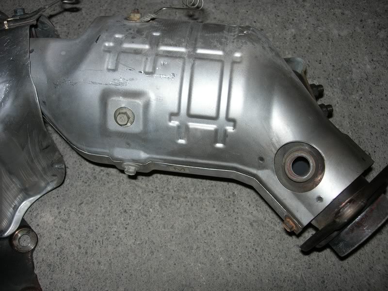
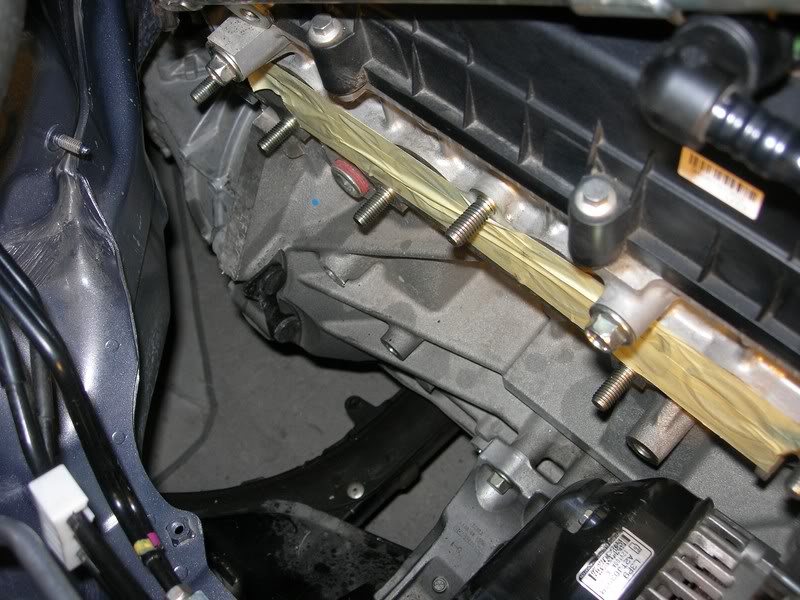
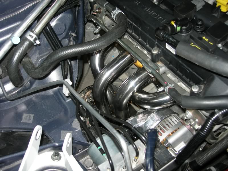
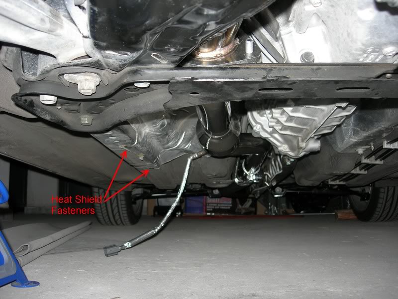
Next we are going to remove the header's heat shields. Use generous amount of WD40 on all fasteners you can see. Spray also the studs at the mid pipe to header connection and the bolts/nuts of the rear muffler to mid pipe.

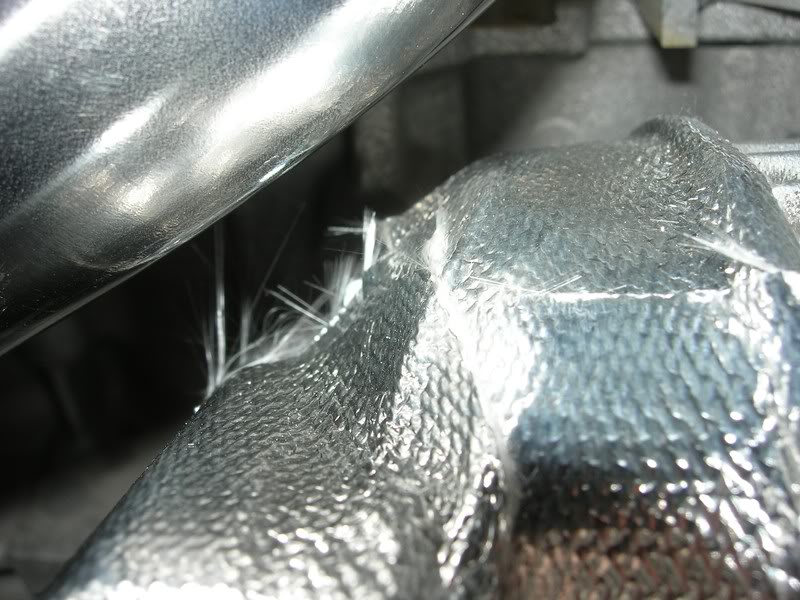
The heat shields are 4 pieces. A top, middle and two on the lower part of the header.

Description: Description: http://i928.photobucket.com/albums/ad121/msstavros/GWR%20Exhaust/DSCN1601ed.jpg


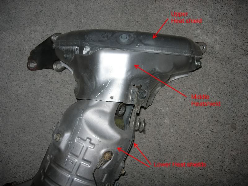
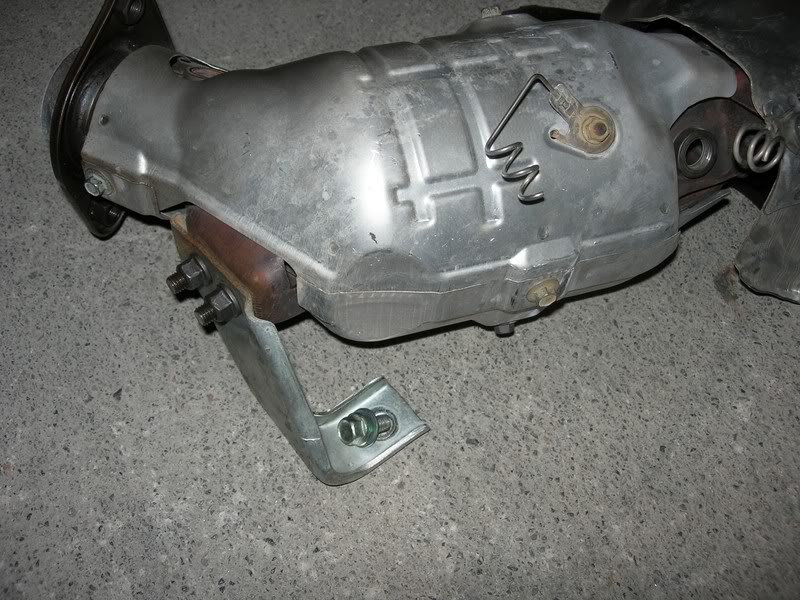
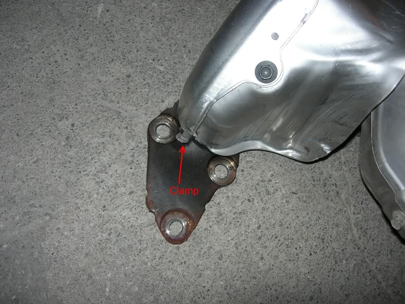
The top and middle are held in place by three bolts where they meet each other. There is also a hidden clamp of sort, on the left side (as you look the header from the passengers side), towards the firewall. Use a flat blade screwdriver to push the clamp open (push towards the firewall).

Description: Description: http://i928.photobucket.com/albums/ad121/msstavros/GWR%20Exhaust/DSCN1602ed.jpg


Use a pair of thick gloves when handling the heat shields, they are razor sharp! The bolts are really tight and here a quality set of sockets will pay for itself. Be careful not to strip the bolts. Mine all came off with a bit 
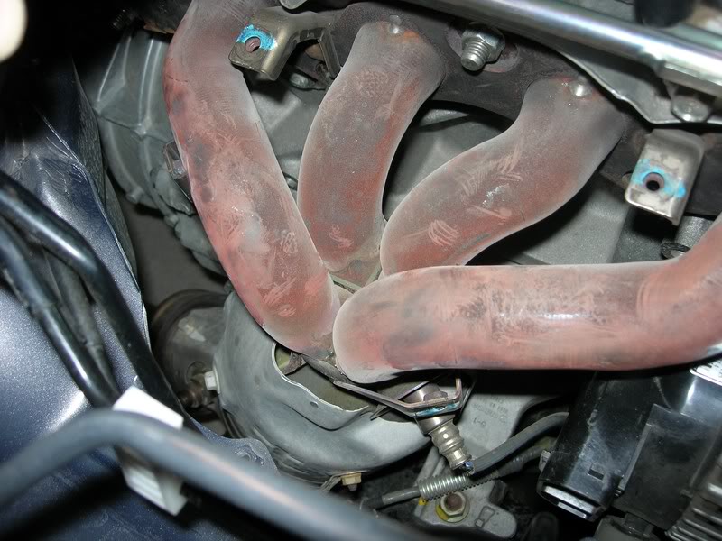
of effort. Remove the two black bolts of the top shield and then the 3 others that hold the middle and top together. Remove the top shield and admire the 
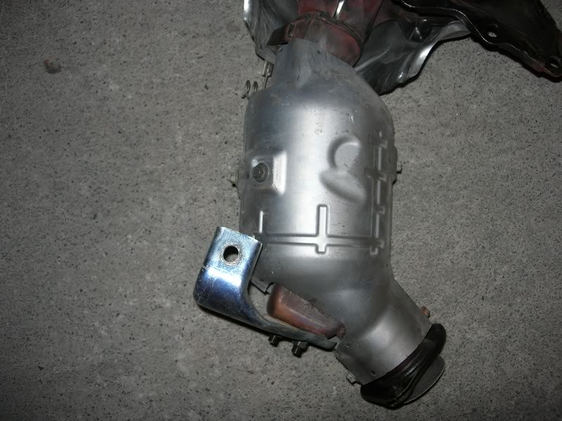
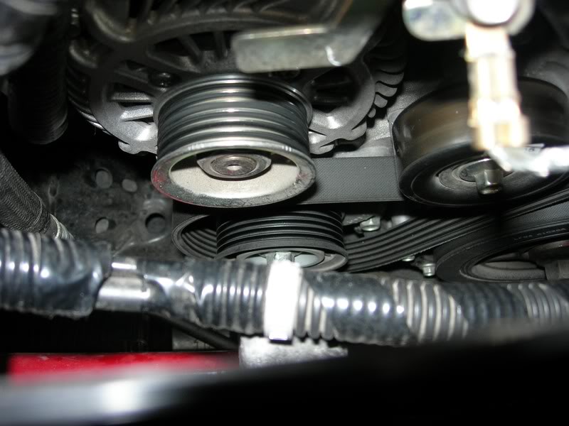
factory header! Use WD40 on all 7 header bolts. There is also another bolt holding the middle heat shield, and the first O2 sensor cable support. Undo the bolt and remove the support from the cable. The middle heat shield will need to be bent to be removed from the car. Try to get it to clear the top of the header, and then fold the left side edge of the shield towards its centre. After some swearing the shield will be off the car :-)

Description: Description: http://i928.photobucket.com/albums/ad121/msstavros/GWR%20Exhaust/DSCN1506.jpg


contd on next post


Description: Description: Old12th August 2010, 04:35

  #2

msstavros

Supporting Member


Join Date: May 2007

Location: Greece

Posts: 112

Undo the O2 sensors connectors. The are located underneath the generator, and are reachable through the wheel arch. Notice that the connectors are one grey and one black, to help you from mixing them.


Next are the bottom shields. I tried to remove the header without removing those, but it was not possible. Save your time and remove them while the header is still in place. Use WD40 on all fasteners. There are 6 bolts holding the shields together. Use the following pictures to aid in locating the position of the bolts:


Use a flat blade screwdriver if needed to separate the two lower shields from each other, and retrieve the
front one (facing the passenger wheel arch) from the top, the rear from the bottom.

Next undo the studs (14mm) holding the mid pipe to the header. Undo the two bolts holding the rear muffler to the mid pipe, and unhook the hanger from the mid pipe. You can now remove the mid pipe and the rear muffler. Pay attention not to damage the header's bottom ring gasket while moving the mid pipe. Remove also the rear muffler. Use dishwashing liquid on all the hangers and they will be quite easy to remove. The rear muffler is easiest to remove, by removing first the two hangers on the passenger’s side, lowering the muffler on the floor, then removing the remaining two hangers from the driver’s side.

Before removing the header, try to pry off the ring gasket at the bottom using a flat blade screwdriver. Be gentle!!! It is a tight fit, but it will come off. A stubby screwdriver may come handy, as there is not much space.

Next remove the header nuts. They will be tight so a medium-large ratchet (long) should be used. Also some nuts may require the use of a universal-joint extension together with wobble extensions. Use the wheel arch area for nuts you cannot reach from the top of the car. The last nut towards the firewall was reachable only by an offset ring spanner. If you have an indexable ratchet this should be easier.
There are also two 14mm bolts reachable from under the car, for the header's lower support. This support should be removed from the engine once the header is out, as it is not needed.

Having undone all the nuts, temporarily remove the header from the engine and retrieve the gasket. Place it somewhere safe. Leave the header on its support, and undo the generator.
There are two bolts on the bottom, and one on top. Back the bolts out, but do not remove them completely. To allow tilting of the generator towards the front of the car, the drive belt must also be removed from the generator. Looking from the front, under the generator's pulley, you can see the auto-tensioner pulley. Use a 14mm socket on a long ratchet and push the ratchet towards the driver's side. The tensioner will move and the belt can be removed from the generator. Ease the ratchet back.


There is also another trick for the header removal. At first I did not want to mess with the generator, and I followed the idea presented on Goodwin forum. You undo the passenger side engine mount, and with a jack under the oil pan you tilt the engine. That is a good trick, but it did not work for me. My car is equipped with the FSTB, and of course it has the cowl bracket. Removing the header was not possible even when the engine was tilted. The generator HAD to be pushed forward, no other way possible, unless I wanted to also remove the cowl bracket (which was really out of question!). Also, should you decide to go with the engine tilting, make sure that you keep the nut fastened on the first 2-3 turns of the engine mount stud. You should do this to avoid lifting the engine too much. If this happens the mount leaves the subframe hole, and you will have a hard time putting it back in. Lowering the engine, does not align the mount stud with the hole. I had to use a BIG hammer to persuade the mount into place :-) Do not worry, I did not hammer the stud!

contd on next post


Description: Description: Old12th August 2010, 04:36

  #3

msstavros

Supporting Member


Join Date: May 2007

Location: Greece

Posts: 112

Start pulling the header out of the car. Take your time, be patient and observe where it hits on the wheel arch, firewall, brake lines, engine, generator... all over the place if I am honest! It is a tight pull as Brian wrote, but eventually it WILL come off! Be very careful not to damage the O2 sensors and/or brake lines!


Once it is out congratulate yourself, the hard work is over! If you are going to continue another day, using some masking tape to cover the open exhaust ports is a good idea:


Remove the O2 Sensors from the header. The first sensor has a dish at the middle which will not allow the use of an open end wrench. You should have an O2 removal socket. Use plenty of WD40 before loosening the sensors. Remove them carefully and clean their threads off any residues. You may also clean the body of the sensor which is outside the exhaust, but do not use anything on the sensor itself. Normally they should have a white-grey colour. Do not clean them leave them alone!
Before beginning the installation of the new exhaust, use the thermal tape provided with the header on the generator's back housing. I bought extra thermal tape and covered as much of the housing as I could as well as the air duct. I have also used the thermal tape to cover the O2 sensors wires as well as the wire extensions.


This is probably overkill and really not required, I just wanted to see how well the thermal tape will hold on the cables. Time will tell. Also it is a safety feature, especially for the extension cables that do not have any heavy duty protective sleeve. I think they are teflon covered, but I am not sure about it. Mine looked like that covered with thermal and aluminum tape.


I am sure that if you omit this step nothing wrong will happen to the cables, as Brian would have included a thermal sleeve on the extension cables should this be required. The only thing you have to make sure is that the plastic connectors do not come into contact with any part of the exhaust, as they WILL MELT. For the second sensor this is not a problem, as I will show you how to route the cable safely away from the exhaust pipe. Only the front sensor connector is prone to touching but we will take care of that latter.

Put the generator back in place and hand tighten the bolts. Take the torque wrench and torque first the two lower bolts starting from the one facing the front of the car to 38-51Nm(29-37ft/lbf) and then the other on the back. Tighten the top bolt to the same torque. Pull the automatic tensioner and slip the drive belt over the generator's pulley. Ease the auto-tensioner and verify the alternator pulley is level with the pulley next to it. If you followed the torque sequence it will.

If you have chosen to undo the engine mount, lower the engine and torque the 17mm nut to 74.5-105Nm(55-77.4 ft/lbf)

Inspect and clean the original header gasket. Normally you should not need to replace it. Mine looked like this (23K Kms)


contd on next post


Description: Description: Old12th August 2010, 04:38

  #4

msstavros

Supporting Member


Join Date: May 2007

Location: Greece

Posts: 112

Remove the masking tape (if installed) from the exhaust ports and place the gasket in place. Lower the new header into the engine and let it touch the lower subframe. Use generous amounts of anti-seize compound on the studs (use a small paintbrush to apply evenly):


Take a header nut and place the header over the gasket. Hand tighten the nut on the top center stud. The header should stay in place. Hand tighten all other nuts and take the torque wrench and tighten all nuts to their final torque, 43-64Nm (32-47ft/lbf) working from the center to the edges (although it should not matter, the Service Manual does not have any specific sequence on these nuts). Where the torque wrench does not fit, use the indexable ratchet or offset ring spanner. Be VERY careful not to let the tools slip and round off the nuts. Use deep sockets (where possible) and make sure you have a perfect and complete fit over the nut before applying torque. Start with the nuts that are easily accessible to get a feel of torque required for the nuts you can only reach with offset spanners.

Reconnect the heater and coolant tank hoses and secure them back on the engine.


On to the mid pipe and the O2 sensors. Apply anti-seize compound on their threads. Do not overdo it, avoid getting any amount of the compound on the sensor part that sits inside the exhaust. The one with the dish should be placed in font of the catalyst, the other one after the catalyst. BE VERY CAREFULL NOT TO CROSS-THREAD the sensors! Both are quite easy to cross-thread, so be patient. Use the torque wrench with the O2 extension and tighten them to 29-49Nm(22-36ft/lbf). You can also see the O2 socket on the torque wrench in the next photo:


Apply the ring gasket on the bottom of the header. I used some anti-seize compound to ease installation. Install the rear muffler on the car. Again use dishwashing liquid to ease installation of the rubber hangers. Get the two parts of the mid-pipe. Slip the ring clamp over one part and connect the two parts together. Do not tighten the clamp. Under the car, raise the mid-pipe and slip the rubber hanger on.

Get the studs (or high tensile bolts and washers if you bought those) and the two springs and temporarily install the mid-pipe to the header. Use a cable tie around the mid-pipe and power plant frame, to help keeping it at proper height with the header. Tighten the bolts until the springs are well compressed. Torque values are 38-52Nm(29-38ft/lbf).


Next is the mid-pipe to muffler connection. Get the bolts(with washers, spring washers) and the gasket and hand tighten. Twist and pull/push the mid-pipe at the slip-joint as far as needed so that it is perfectly aligned with the muffler. Pay attention to have the gasket aligned with both parts too. Tighten the nuts to 38-52Nm(29-38ft/lbf).

Remove the cable tie, and check for possible clearance issues. Mine was perfectly aligned first time (evidence of the quality of the exhaust system! Kudos to Brian!) If you have the Beatrush/ILMO underbraces, you may want to have some extra clearance between the mid-pipe and the
butterfly brace. For what is worth, GWR mid-pipe leaves more space than the factory, but nevertheless here is a trick I picked from the local dealer: Use two cable ties, one vertically across the length of the hanger (top to bottom) and the other horizontally, to keep the first one from moving. Tighten the vertical as needed to move the exhaust further up towards the car. You should not need to tighten so much as to deform the hanger, the cable tie is just there for minimum adjustments, and to keep the height constant as the rubber hanger deteriorates / sags over time:


Tighten the ring clamp over the slip-joint of the mid-pipe (10-15ft/lbf)
Install the O2 extension cables to the sensors. For the rear sensor, remove the two black fasteners of the catalyst heat shield under the car (red arrows).

contd on next post


Description: Description: Old12th August 2010, 04:39

  #5

msstavros

Supporting Member


Join Date: May 2007

Location: Greece

Posts: 112

Be careful to avoid damaging the heat shield. Use a pair of bent needle nose pliers as they are really tight. Removing them will allow for the extension cable, and the connector to be routed on top of the shield, therefore protecting them from the heat. Use 2/3 pieces of aluminum tape (on top of each other) on the holes of the heat shield to reinforce it if you damaged it. Replace the fasteners.


Route the rest of the cable together with the cable from the first sensor as far away from the header as possible. Use cable ties to hold them on the brake lines visible from the passenger's wheel arch


Finally connect them to the original connectors under the generator. Pay attention to the colours, grey to grey, black to black.

To protect the first sensor's connector (sensor to extension cable) from possible heat damage, use some heat shield tape on the connectors. Do not overdue it, you still want to be able to open the connectors for a possible O2 replacement in the future!

Installation of the full exhaust is now complete. We have to re-install all the underbraces, battery, fstb, bottom oil pan plate the outer header heat shield (brake line protector) and we are done. Torques of various components on the following pic (sorry, only Nm)


Upon connecting the battery, do not forget to perform the steering wheel angle sensor initialization, if your car has the DSC. Since I had spare thermal tape, I used some to cover the inside of the brake lines heat shield before reassembly on the car:


Reinstall the tire, remove the jack stands and lower the car on the ground. Before firing up for the first time, double check that everything is in place (hoses, O2 connectors, drive belt, generator tight). Do the DSC initialization (if applicable), and fire up the car. If your idle hunts momentarily this is quite normal. It will hunt even on the first drive a couple of times. After two or three starts it will be rock solid. This is normal and I have experienced it before when I disconnected the battery for the CAI install. It is the ECU calibrating itself... Listen for unusual noises and do the first few miles with caution. After about 100 miles, all fasteners should be rechecked for correct torque.

I had a ringing sound from the glass packed baffle after some miles, at 50-100rpm above idle. I used about a ˝ feet of teflon tape around the baffle and that cured it. So far no problem with the teflon burning. Remember to use anti-seize compound on those baffle bolts too!

As far as emissions go, it did pass the emissions check, although I cannot be sure how accurate was the emissions tester. There is the well known smell from the catalyst when cold, but this was also the case with the stock exhaust, it is just a little more pronounced now. In the future I am planning on installing a 200cpsi all metal catalyst Euro4 compatible. But this will have to wait though, I am kind of broke and really enjoying too much my new car!

Some may say the exhaust is kind of loud, the beautiful thing about it though is that it is almost stock silent at idle, and not at all loud during normal driving. It is during WOT that the sound changes to a completely different animal! I cannot give an unbiased review on this exhaust, all I can say is if I had to do it again, I would in a blink!


Description: Description: Old16th August 2010, 13:18

  #19

msstavros

Supporting Member


Join Date: May 2007

Location: Greece

Posts: 112


It will be difficult to add them after the header is in place. There is not much space available, and the header does not make it any better :-)

See the following pictures. I took those after placing the header in place. The top alternator bolt is not tightened, but this is the normal position of the alternator (i.e. it is not tilted at all in the pictures).


Maybe, if you tilt it, you might be able to do it, but then again, you will have to remove at least the outer heat shield (brake lines).
I would try to do it before installing the header in place...